
Abstract
The article deals with integrating the inertial navigation unit implemented into the system of controlling the robot. It analyses the dynamic properties of the sensors of the inertial unit, for example, gyroscopes and accelerometers. The implementation of the original system of controlling the mobile robot on the basis of autonomous navigation systems is a dominant part of the article. The integration of navigational information represents the actual issue of reaching higher accuracy of required navigational parameters using more or less accurate navigation systems. The inertial navigation is the navigation based on uninterrupted evaluation of the position of a navigated object by utilizing the sensors that are sensitive to motion, that is, gyroscopes and accelerometers, which are regarded as primary inertial sensors or other sensors located on the navigated object.
Introduction
The word ‘inertial’ comes from the original word ‘inertia’, which means inertia and inability of motion. The principle of inertial navigation obeys the laws of classical mechanics defined by Newton. The inertial navigation system (INS) includes at least one navigation computer and a platform or a module containing accelerometers and gyroscopes. 1,2 From the constructional point of view, inertial navigation systems are divided into platform so-called gimballed systems and non-platform so-called strapdown systems. In the platform system, inertial sensors are attached to the platform that is installed in a gimbals suspension with three degrees of freedom with the aim of remaining the constant space orientation in defined directions (north–south, east–west and vertically on performing the gravitational attraction), while the gimbals suspension is firmly connected to the construction of the navigated object. The moving mechanical parts of the systems cause 3 relatively low reliability towards the non-platform systems. The inertial sensors of non-platform systems are firmly connected to the construction of the object (usually in the centre), for whose navigation they are determined.
Both types of the inertial navigation systems consist of an inertial measurement unit (IMU) and a navigation computer. The IMU is an underlying element of each INS. Sensors whose output is influenced only by the motion of the object, on which the IMU is placed, are regarded as primary sensors of the IMU. Sensors of angular velocity whose output signals after integrating are used for determining the orientation in space, and accelerometers whose output signals after precise compensating the gravitational acceleration and Coriolis force can be integrated for speed and position are the primary sensors in the inertial navigation. 4 Such an IMU has six degrees of freedom, which means that it enables measuring the translational and rotary motion in three orthogonal axes.
In the autonomous navigation, the accuracy of inertial sensors plays a key role. The errors of current inertial sensors have the value of approximately 0.01°/h for gyroscopes and 100 µg for accelerometers. The mentioned errors are integrated in time and cause an error of determining the position that is expressed by non-accuracy of measuring per hour, which is, however, minimal. Such high-powered IMUs are implemented only into the inertial navigation systems for a special use where the highest possible accuracy is required. In less demanding applications, more affordable IMUs are used. Their lower accuracy is compensated by implementing into the integrated navigation systems in which the required accuracy is achieved by integrating the navigation information from more navigation systems. The ADIS16365 inertial sensor, 2,5 which has been produced since 2009, belongs to the novelty in the sphere of such IMUs. The ancestor of this sensor (ADIS16350) was awarded in the Best of Sensors Expo 2007.
The ADIS163 xx inertial sensor is determined for the applications of guidance, control and stabilization of the body with six degrees of freedom in space. The sensor can be used for controlling and an analysis of motion, navigation and stabilization of the body or an image in different applications. As a part of the integrated navigation system, it is suitable for using in the area of robotics for the navigation and control of autonomous mobile robots. The software for controlling the automatic calibration of the system error, sampling, digital filtration, the internal test of sensors, feeding, monitoring the state of the sensor and the additional digital I/O port is implemented into sensor circuits. 6,7
From a structural point of view, inertial navigation systems are divided into platform (cardan INS) and non-platform systems (strapdown systems). In platform systems, inertial sensors are mounted on a platform installed in a cardan gimbal with three degrees of freedom, in order to keep a constant space orientation in predefined directions (north–south, east–west and perpendicular to the earth’s gravity effect), while the gimbal is fixed to the structure of the navigated object. Movable mechanical parts of these systems cause relatively low reliability compared to non-platform systems. In non-platform systems, inertial sensors are firmly attached to the structure of the object, the navigation of which they are determined for. Both types consist of an INS IMU and a navigational computer, as illustrated in Figure 1.
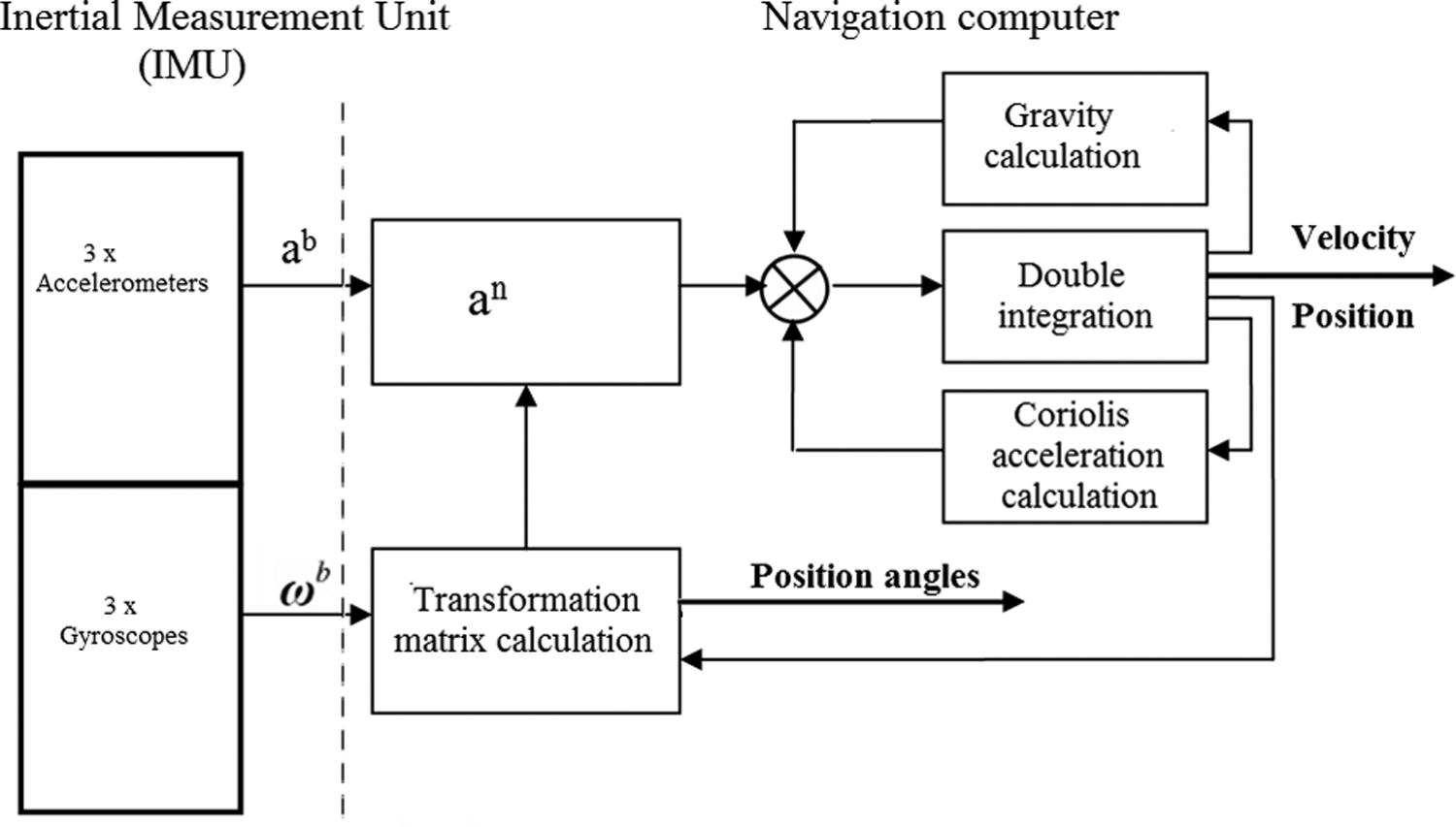
Block diagram of the INS working in the navigation coordinate system.
A navigation computer is the core of the inertial navigation system. The navigation computer processes the measured data from the IMU and generates information about the angular position, the velocity and the position of the navigated object based on the known initial conditions. The measured data from the gyroscopes represent the angular velocity vector of the navigated object regarding the inertial coordinate system marked with the index ‘i’ and measured in individual axes of Cartesian coordinate system of the navigated object marked with the index ‘b’ (b stands for body)

By application of more mathematical modifications and integration of the angular velocity, the information about the position of the navigated object in regard to the reference system is attained (direction, tilt, inclination, respectively transformation matrix or quaternions). The data measured by the three-component accelerometer represent the vector of acceleration measured in the axes of the navigated object

After the initial data processing, the data are transformed into the reference system. Then, compensation of gravity and Coriolis acceleration is carried out, followed by dual integration. The first integration offers information about the velocity of the navigated object in the reference system, while the second integration provides information about the object location. Although a navigation computer seems to be based on a simple principle, it actually comprises nine differential equations, respectively, and three differential equations in vector shape (form). However, these equations are not required to be stated in this contribution.
The implementation of an inertial system into the system of controlling a mobile robot
In contemporary space demands and the effective utilization of space, the mobile robot is forced to work in confined conditions, and the motion of a tool or the manipulation with parts requires surgical accuracy. This gives considerable demands for the right calibration of the robotic device. 8
The accuracy of the mobile robot is characterized first and foremost by the size of the deflections of its effector on the working arm from the specified position. So far, it has been possible to determine the trajectory of the arm or the working tool of the mobile robot during the motion in space only by photogrammetric methods. 9 Ensuring higher accuracy is enabled by geodetic methods. However, they require the arm of the mobile robot to be at rest. Determining the position of the arm in space with required accuracy even if the arm is moving is enabled by inertial measuring systems. 10 In principle, it is determining the trajectory of the controlled point of the arm, while the task is solved in the conditions characteristic just for the control of industrial mobile robots.
The principle of inertial determining the position embodies in constant processing the information flow about the motion of the object, that is, continual measuring the vector of instantaneous acceleration and slewing. It is measured in a coordinate system 11 defined by the construction of measuring system, so it must be transformed to such a system in which determining the position or trajectory is required. The information needed for transformation can mostly be obtained from gyroscopic measuring. In rare cases, non-requiring high accuracy in determining the position or in very small values rotations of the system is relatively expensive, and sensitive gyroscopes are replaced by sensors of angular acceleration or power.
The structure of mobile robots is not unified. There are a lot of conceptual and constructional solutions of robots resulting from the expected utilization. A robotic system can be divided into a mechanical and control subsystem irrespective of their solution. The motion of working organs of a mobile robot is provided by mechanical parts. The activity of all the parts of the mobile robot and programming of its expected activity are enabled by the control subsystem.
The mobile robot or its part (gripper and arm) has to meet the requirement of three degrees of freedom of motion in the X-axis, Y-axis and Z-axis at a minimum to achieve a random point in space. The next three degrees of freedom are needed for the random orientation in a given point towards a manipulated object. It means that a universal mobile robot must have six and/or more degrees of freedom. A mechanical conception of the mobile robot is determined by a number of degrees of freedom.
Accuracy of inertial sensors plays the key role in the autonomous navigation. Errors of the current inertial sensors achieve the value of about 0.01°/h for gyroscopes and 100 µg for accelerometers. The aforementioned errors are integrated in time and lead to the error of positioning determination expressed by inaccuracy of measurement per hour; for modern IMU, this error is approximately 2 km/h. The commercial price of a high-end IMU is about €100,000. Such high performance and expensive IMUs are implemented only into the inertial navigation systems for special applications when the highest possible accuracy is required.
The analysis of dynamic qualities of an electronic gyroscope
Inertial navigation is based on measuring the relative movement of a mobile object (any object such as airplane, automobile, robot, etc., the location, velocity and orientation in space of which need to be continuously determined), grounded on the known initial position. From the initial value, the size, the direction of acceleration action and the angular velocity are measured, as well as the double integration, with respect to time and for the purposes of obtaining accurate information about relativity motion, is performed.
The possibility of the utilization of electronic gyroscopes in robotic systems issues from their metrological parameters in determining the data as well as from dynamic characterizations. The analysis of the mentioned parameters was determined by measuring on a laboratory model, which is created by a test electronic gyroscope, a discrete linear drive and a control microcomputer. 12 The linear discrete drive is realized by the four-phase KM, which by means of the SD20M MICROCON control system is operated by the MCBSTM32C (ARM) development board. A gear of control impulses to linear periodic motion, which is scanned by an inertial sensor of acceleration, was achieved by controlling and mechanical arrangement. A flow chart of an electric drive model is illustrated in Figure 2.

A flow chart of an electric drive model.
The principle of monitoring is based on the scanning of acceleration of linear periodic motion by the MEMS sensor. Next, the analysis of the influence of acceleration dynamic changes by different modes of driving a stepper motor follows. Prior to scanning the acceleration of the linear periodic motion, a sequencer was set for basic microstepping so that the influence of a shape of the KM actuating current was the most striking on the scanned acceleration of a rotor. Signals were scanned to a PC by a constant period T = 1.22 ms by means of the Analog Device – ADIS163xx Evaluation Software – Rev 14.
A graphic environment in MATLAB with the utilization of functions for the discrete Fourier transform and filtration (Figure 3) was created for the analysis of the measured signals. A bandpass filter is needed to identify an item distinctive for the analysis of dynamic parameters of the electronic gyroscope. The MATLAB fir1 function was used to propose the filter. The fir1 function uses a classical window method of a proposal of the digital Finite Impulse Response (FIR) filter with a final impulse response. A vector of b-coefficients is returned by the function. Using the FIR bandpass filter in the interval from 11 Hz to 33 Hz, the courses in the time area for a used actuating signal are obtained. In Figure 4, there is a time function with a medium value of the acceleration amplitude 7.1 × 10− 3 ms− 2, which responds to the sinus actuating signal, and in Figure 5, there is a time function with a medium value of the acceleration amplitude 10.2 × 10− 3 ms− 2, which responds to the special actuating signal.

A graphic environment in MATLAB for the analysis of measured signals. A course in a time area together with the DFT in a sinus actuating shape of the KM is illustrated. DFT: discrete Fourier transform.
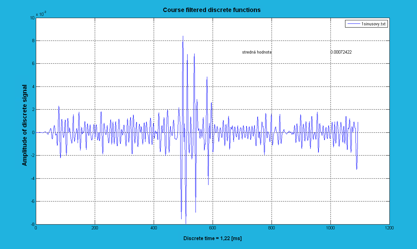
The FIR signal filtered off by a bandpass filter – the sinus actuating shape.

The FIR signal filtered off by a bandpass filter – the special shape of actuating.
The ADIS16355 inertial sensor
The ADIS16350 sensor seems to be a suitable inertial sensor. The ADIS16350 sensor is the inertial sensor for measuring angular velocity and acceleration in three axes. The sensor consists of the MEMS components and circuits of signal processing with the aim of a highly integrated solution. Calibrated digital measurements of position and acceleration are thus enabled. 13,14 The sensor output data are accommodated to the communication by the SPI bus standard. The SPI bus guarantees structurally a simple input–output interface and the comfort of programming. The characterizations of a described sensor with a rising working temperature are markedly deteriorated. The ADIS16350 electronic gyroscope achieves higher temperature resistance. 15
From the basic technical parameters of the ADIS16355, the sensor follows that it is needed to provide its operation in thermally stabilized space. As the sensor shows deviations in measuring depending on time, as long as this data increases exponentially, carrying out of the sensor calibrating in short time intervals is needed. The calibration lies in a transfer of the mobile robot arm to a reference point (i.e. a point with known coordinates from zero points of a machine and work piece, e.g. X, Y, Z, OX, OY = 0, 0, 0, 0, 0). After this work, it is controlled whether a monitored measuring system shows zero coordinates. If different data are shown, an instruction for correcting the measuring system comes and, by means of it, the system is set up to the reference coordinates/the reference point.
The integration of several navigation systems is a complex process; however, thanks to the availability of high quality and accurate sensors such as ADIS16350 and its heat-calibrated equivalent ADIS16355, it currently represents a suitable and sufficiently accurate alternative to expensive and super accurate primary navigation system.
A flow chart of the inertial system applied in the controlling of the mobile robot
The control computer, as it is illustrated in, is a basic part of the system. Signals from sensors are processed and evaluated by the control computer, and on their basis, it carries out an action hit by which the mobile robot arm motion is provided (e.g. a process of welding after a required trajectory). The mobile robot can work in an automatic mode but also in a manual mode when the control computer processes and carries out instructions from a service of the mobile robot. The control computer communicates through the A/D converter with a block controlling the process of welding, and thereby, it also controls the process of welding.
Servomotors have circuits (interpolator, bidirectional counter and incremental scanner of position) that are able to regulate the velocity of motion. This is used mainly in the manual mode when the velocity of motors is lowered due to the protection and safety of the service. An incremental scanner of position generates an impulse by the change of position of a servomotor shaft about a unit of position. The impulses from the interpolator and incremental scanner of position are added up in the bidirectional counter in such a way that in a required positive motion, the impulses from the interpolator are added up and they are subtracted from the incremental scanner. An error voltage arises in the output. In a polarity of this voltage, a sense of the error is expressed. An amplifier is connected either to the bidirectional counter or to the scanner of absolute position; its shaft is joined tightly with the servomotor shaft by means of the gear. Switching is controlled by the control computer, by which the velocity information is given to the interpolator and a value of new position is given to the register of position.
A camera is connected to the control computer via the A/D converter. Signals from the camera are analysed and utilized for the control of welding accuracy. A touch sensor is represented by an infrared (IR) detector, which serves for detecting obstacles in a near environment of the mobile robot, the tens of centimetres. This sensor provides a binary signal – it detects a reflected IR signal/it doesn’t detect a reflected IR signal or it detects an obstacle/it doesn’t detect an obstacle. These sensors are utilized in setting up the zero and reference points; they are also utilized in guiding the arm to these points in order to avoid a collision between the arm and work piece in the raid to the reference position.
An IMU block consists of gyroscopes, accelerometers and temperature sensors (Figure 6.). The mobile robot arm motion is recorded by them, and the information about direction and velocity of motion is given to the navigation computer, by which the information is given to the control computer. The information is depicted on a display by the navigation computer, then it is compared with the coordinates required by the program or service, and consequently, the motion of the mobile robot is controlled in order to achieve the required coordinates. Connecting between the INS (IMU + navigation computer) and the control computer is realized through the SPI duplex bus. Next, the mentioned bus is used for resetting the inertial system or triggering diagnostics and system tests.
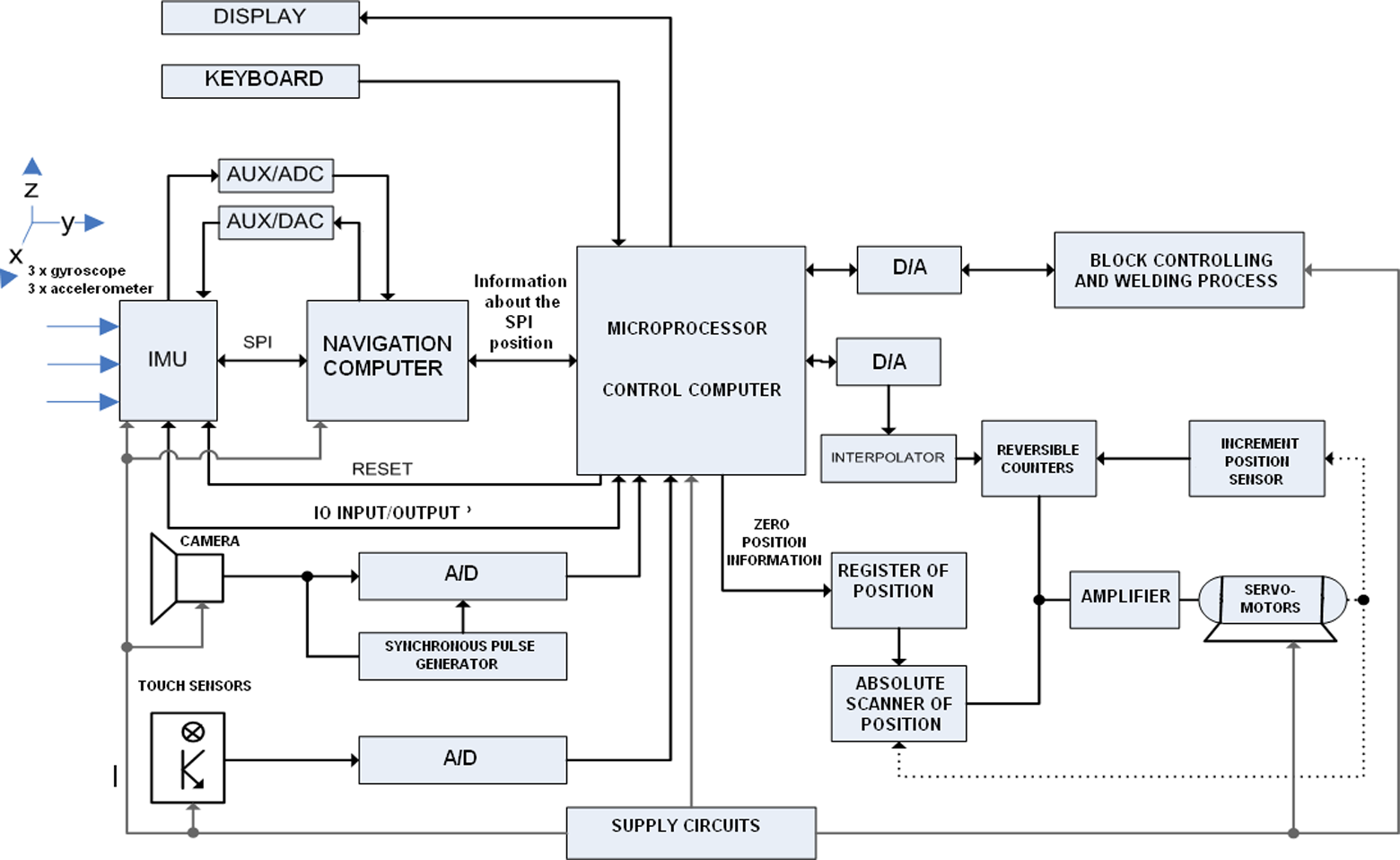
A flow chart of the robot with the applied inertial system.
An application for the controlling of the mobile robot by the inertial system
In implementing the inertial system to the controlling of an industrial and mobile robot with five degrees of freedom, the connecting to a control process computer is also needed. To connect the mobile robot to the control computer is the most frequent and the simplest way of controlling in practice.
The immediate position of single mechanisms of the mobile robot is identified by a common control system via integrated position sensors. By implementing the inertial system on a mobile robot arm, the position sensors are not needed, and the arm position is evaluated by an autonomous inertial system. The mobile robot arm position is evaluated by the mentioned system on the basis of knowledge in the initial (reference) position and subsequent scanning of the arm motion by the inertial sensor.
The considerations and results mentioned in the previous section can be applied wherever GPS navigation is not available and where it is necessary to accurately identify the monitored object. The collected information can be utilized in designing a mobile robot with a control program able to review its position in the real coordinate system, and thus, it is suitable for navigation even in unfamiliar environment (e.g. in an underground geological survey). 16
An application mobile robot has five degrees of freedom. It means that it works in the 3D coordinate system X, Y and Z. The next two degrees of freedom are in the rotary movements of the mobile robot arm (welding robot), as illustrated in Figure 7.

A schematic representation of the mobile robot with the applied inertial system.
After switching off, the control system loses the information about position. Therefore, there is a reference point on the mobile robot. The system recognizes the distance of the reference point from zero points of the machine and work piece. 17,18 Therefore, after switching on, the mobile robot arm must be given to the initial point by the system, so that the initial (reference) coordinates were set up. The coordinates of the reference point are determined by the position of the sensor, and they can be changed according to the need in the pod MENU – CALIBRATION AND TESTS OF SENSORS. After switching on the system, the TEST INS function is activated as the first.
The course of the TEST function is as follows: the mobile robot arm is set up to the position of the reference point and it is controlled whether the coordinates consistent with the coordinates of the reference point are returned by the inertial system. If not, the inertial system for the defined coordinates is calibrated. Then, the arm transfer to the maximum coordinates follows. It is then controlled whether the coordinates consistent with the coordinates of the maximum point are returned by the inertial system. If not, the correct coordinates are set up in the inertial system. After these steps, the inertial system is calibrated, and the functions of the mobile robot can be opened up.
The TEST function, which is carried out after activating the mobile robot, is necessary for the correct function of the inertial system applied in the controlling of the mobile robot. Consequently, the motion to the reference position of the mobile robot arm after each manufactured product is performed. This mode is also utilized in classical gauging systems, which are equipped with relative sensors of the IRC position (e.g. CNC machines). The calibration of the system is realized by guiding the movable part to the reference position after each machined piece work.
Conclusion
The development in the sphere of MEMS technology brings new, complex (also affordable) solutions of sensors suitable for integrated navigation systems with extensive possibilities of utilization. 6
The submitted contribution represents the original way of controlling the mobile robot by the inertial system. Sensors of position, selsyns, are used in classical mobile robots for determining the actual position of their parts (gripper and arm). The inertial system is responsible for determining the actual position in the described system of controlling the robot. Regular calibration of sensors deflection is a necessary for the correct activity of the inertial system. If the condition was not fulfilled, the deflection would constantly grow, and big differences between the real position of the robot and the position given by the inertial system would appear. In practice, it is inadmissible. Inertial systems are constantly developed; therefore, by improving the sensors, mainly by minimizing the errors of accelerometers and gyroscopes, more perfect and accurate inertial systems appear. 19
The proposed mobile robot is able to work autonomously, automatically according to the program or manually according to the instructions from the service. The instructions of the service are given by means of a keyboard. The improvement of manual controlling the mobile robot would be the use of an arm-eye system, which would markedly improve the possibilities of the service to use the mobile robot more effectively.
The possibilities of utilizing the inertial systems are directly proportional to the advance in their development. The ability of precise measuring the position of the mobile robot mainly in necessarily regularly repetitive calibration is increased by this. The implemented INS is able to measure accelerating and slewing of robotic arm watched point and thus to determine the position of the mobile robotic arm in space. 19
The configured first hardware and software is able to achieve the needed values of measuring the position and even on the 3D surface.
Footnotes
Declaration of conflicting interests
The author(s) declared no potential conflicts of interest with respect to the research, authorship, and/or publication of this article.
Funding
The author(s) disclosed receipt of the following financial support for the research, authorship, and/or publication of this article: This publication is the result of implementation of the project ‘UNIVERSITY SCIENTIFIC PARK: CAMPUS MTF STU – CAMBO” (ITMS: 26220220179) supported by the Research and Development Operational Program funded by the EFRR.