
Abstract
Global Positioning System and Inertial Navigation System can be used to determine position and velocity. A Global Positioning System module is able to accurately determine position without sensor drift, but its usage is limited in heavily urbanized environments and heavy vegetation. While high-cost tactical-grade Inertial Navigation System can determine position accurately, low-cost micro-electro-mechanical system Inertial Navigation System sensors are plagued by significant errors. Global Positioning System is coupled with Inertial Navigation System to correct the errors, while Inertial Navigation System itself can be used to provide navigation solution during a Global Positioning System outage. Data from Global Positioning System and Inertial Navigation System can be integrated by extensive Kalman filtering, using loosely coupled integration architecture to provide navigation solutions. In this study, real-time low-cost loosely coupled micro-electro-mechanical system Inertial Navigation System/Global Positioning System sensors have been used for pedestrian navigation. Trial runs of Global Positioning System outages have been conducted to determine the accuracy of the system described. The micro-electro-mechanical system Inertial Navigation System/Global Positioning System can successfully project a trajectory during a Global Positioning System outage and produces a root mean square error of 9.35 m in latitude direction and 10.8 m in longitude direction. This technology is very suitable for visually impaired pedestrians.
Keywords
Introduction
Global Positioning System (GPS) and Inertial Navigation System (INS) are widely used to determine position, velocity, and time (PVT) for navigation applications. GPS is a satellite-based navigation system which provides accurate positioning information. Although GPS has superior long-term performance in minimizing navigational errors, it has poor short-term accuracy when a GPS signal is unavailable. In order to overcome any temporary outage of GPS signal, GPS may be coupled with INS in navigation systems. INS has good short-term accuracy, but it has poor long-term performance, making integration of INS and GPS system ideal. When the GPS signal is unavailable, INS can provide short-term robust navigation solutions until the GPS signal is once again available.
Kalman filtering is an optimum estimation algorithm characterized by recursive evaluation and estimation of the dynamics of the system model. Conventional Kalman filtering is a time-discrete and linear system. The time-variant stochastic error that an INS produces may result in the reduction in the observability of error states. 1 An extended Kalman filtering (EKF) assumes a nonlinear dynamic system with the presence of process and measurement noise, which is assumed to be Gaussian white noise with zero mean and known error covariance matrices. 2 An EKF integrates the measurements from GPS and INS, using position and velocity from GPS to update error states while using INS as a reference trajectory.
Proliferation of micro-electro-mechanical system (MEMS) inertial sensors would result in low-cost INS/GPS systems. The current smart phones are already equipped with multiple MEMS sensors. These include accelerometer, gyroscope, e-compass, altimeter, and humidity sensor. There was also a study using MEMS olfactory sensor3–6 to monitor air pollution. 7 In order to use an inertial measurement unit (IMU) as an INS, the INS needs to be initialized from either coarse alignment or fine alignment. 8 Obtaining the acceleration and angular rotation from IMU, the INS mechanization equations convert the measurements into PVT information. There are two modes of INS mechanization equations which are the gimbal INS and the Strapdown Inertial Navigation System (SINS). Gimbal INS involves mounting sensors on three orthogonal rotating gimbals, while application of MEMS IMU sensors in SINS will involve mounting them on printed circuit boards without moving parts. 9
The current smart phone technologies have its limitations in terms of GPS signal outage. For visually impaired pedestrians, expensive solutions using real-time kinetic (RTK) method are available to provide sub-meter accuracy based on subscription basis. However, based on World Health Organization’s estimate of 285 million visually impaired people worldwide, more than 90% of them live in low-income settings. Our aim is to make sure of current low-cost INS/GPS system to provide alternative low-cost solution.
Traditionally, INS and GPS can be coupled via different modes, namely, loosely coupled integration and tightly coupled integration. 10 In the loosely coupled integration, PVT information from GPS updates the INS/GPS Kalman filter and feed backs the sensor error states to the INS mechanization equations.11–16 In tightly coupled integration, it utilizes a centralized Kalman filter that integrates pseudorange and Doppler measurement from GPS and PVT information from INS.17,18 Although tightly coupled integration is more accurate and less sensitive to stochastic error model than loosely coupled integration, it is computationally expensive and the processing time is not suitable for low-cost MEMS application. In this work, MEMS IMU and GPS sensors will be used, and a loosely coupled INS/GPS system will be implemented to compute real-time pedestrian navigation solutions using EKF. This could potentially be used in many handheld gadgets with the potential of low-cost solution for the visually impaired.
Method
INS mathematical formulation
Coordinate frames
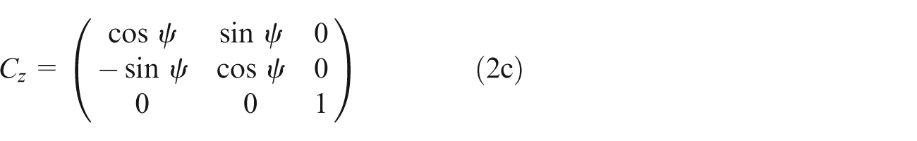
The linear and angular motion of one coordinate frame needs to be described with respect to one another. Measurements from the IMU need to be described as Euler’s angles roll θ, pitch φ, and yaw ψ to be rotated to navigation frame using a rotation matrix known as attitude, C


INS initialization
INS position and velocity must be initialized from external navigation systems like external INS and GPS or initialized using a pre-surveyed point. In this work, the INS is initialized from the position and velocity from GPS.
To obtain attitude of the INS
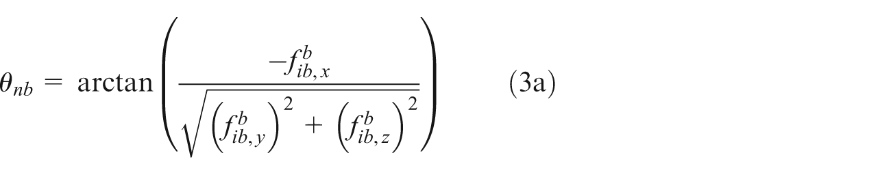

where measurement from accelerometer is denoted by
During the gyro compassing process, since the INS is stationary, the only rotation a gyroscope can sense is the rotation of Earth in the z-direction of the Earth frame


where
Using Euler’s angles obtained, attitude is derived from equations (1) and (2).
INS mechanization
INS mechanization equations update its position and velocity based on values obtained in its previous iteration (Figure 1). In the first iteration, position and velocity are obtained from GPS information and the attitude is determined from coarse alignment. The velocity of the INS can be updated as a function of gravitational vector and Earth rotation matrix in the standard World Geodetic System (WGS-84). 19 Finally, using second-order Runge–Kutta integration, the position of the INS can be computed as shown in Figure 1.

Schematic block diagram of INS mechanization.
The attitude of the INS is updated as follows

where

Earth rotation matrix
When deriving the velocity vector

where
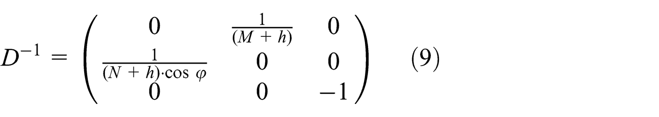
To obtain the position vector

where
INS error state
INS mechanization equations in the previous section described the updated navigation state vectors without consideration of IMU error. The error state vector
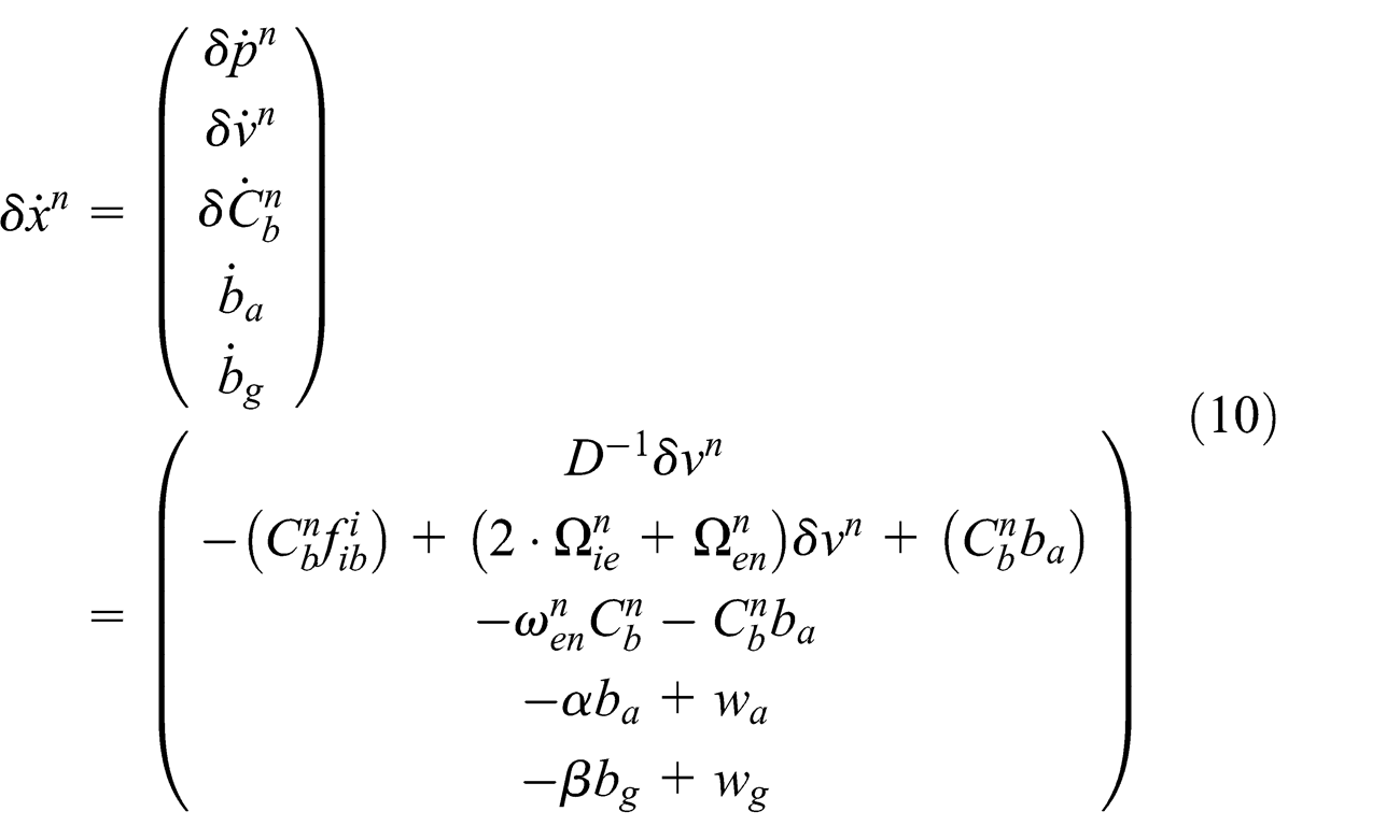
The gyroscope and accelerometer bias are residual stochastic errors


where
INS/GPS integration architecture
Kalman filtering
The Kalman filter is an estimation algorithm that operates recursively based on the previous estimates and prior information. It consists of two stages, the prediction stage and the update stage. The EKF assumes that the dynamic of the system model is a discrete time system. 2
In the prediction stage, the state vector (

where
Error covariance matrix

In the update stage, Kalman gain is computed, state vectors are updated, and the error covariance is updated

where
The state vector is then updated using Kalman gain calculated at its current epoch

where
The error covariance matrix is then updated

Prior information such as the transition matrix
The transition matrix

where full expression of system matrix
Process noise matrix

where
The observation matrix

The shaping matrix

Noise measurement matrix

In the state-space model, error of the state vector and measurement vector is calculated.
System dynamic model of the EKF can be expressed as

where
Measurement model of the EKF can be expressed as

where
In the INS/GPS system, the measurement vector

Loosely coupled INS/GPS
After INS mechanization equations, the state vector will be calculated. Combining PVT information from GPS and the state vector of the INS into the Kalman filter, the position and velocity can be predicted and updated. When there is no GPS signal, the INS Kalman filter will predict the position and velocity based on state space model of the INS (Figure 2).

Schematic block diagram of INS/GPS loosely coupled integration.
The GPS device processes the PVT information in standard National Marine Electronics Association (NMEA) signals 19 which will then be processed into geodetic location and velocity-over-ground. Once the GPS device receives a lock from the satellite, 19 the PVT information will be used to initialize the INS mechanization equations.
The loosely coupled INS/GPS architecture cascades the GPS information into the centralized INS/GPS Kalman filter with the INS state vectors to derive INS/GPS position and velocity based on the state system model used in equations (23) and (24). In the closed-loop set-up, the IMU bias will be fed back to correct the INS error states used in equations (11) and (12).
Modeling of INS error
To derive
Velocity random walk and bias instability of accelerometer.

Angular random walk and bias instability of gyroscope.

To derive
Experiment procedure and hardware selection
The purpose of this study was to implement a pedestrian INS/GPS system. To verify the accuracy of the INS/GPS system, the experiment was conducted in clear weather on a 400-m circular stadium track to determine the accuracy of the system. To simulate GPS outage, the daughterboard of the GPS device was switched off for 20 s at time 120 s (Figure 3).

A Google Earth image of the path taken during the experiment conducted on lane 4 of a stadium track. The yellow dot is the start of the simulated GPS outage 120 s after the start of the experiment. A GPS outage was simulated by switching the GPS daughterboard off for 20 s.
The hardware implementation was performed in three stages. The first stage consists of the design and calibration of the commercially off-the-shelf IMU. The second stage was coding and implementing EKF onto the INS/GPS system and the third stage is to verify the performance of the INS/GPS system. The IMU digital combo (SparkFun, USA) that consists of a tri-axial accelerometer ADXL-345 (Analog Device, USA) and tri-axial gyroscope ITG-3200 (Invensense, USA) is used. IMU measurements are updated at 10 Hz. The low-cost GPS module is a u-blox LEA-5H GPS (u-blox, Switzerland). The GPS format is in NMEA format and it updates at 2 Hz. The microcontroller used is the Arduino Due (Arduino, Italy). The Arduino Due is a 32-bit ARM core running at 84 Hz.
Results and discussion
Experimental data collected were processed in MATLAB/Simulink Kalman filter, and the geodetic data were processed using MATLAB mapping tool.
Figure 4 shows the comparison of the two trajectories taken with an active GPS and during a simulated 120-s GPS outage after the start of the experiment. During the GPS outage, there was a drift from the original trajectory, indicating that INS Kalman filter was predicting the geodetic location (Figure 4). The drift of the trajectory was caused by the bias instability of the MEMS IMU sensor.

Comparison of the two trajectories (solid blue line: without GPS outage and solid brown line: with 20 s GPS outage) taken with an active GPS and during a simulated 20 s GPS outage after the start of the experiment.
From Figures 5 and 6, at time 120 s, there are the latitude and longitude errors increased during the time duration of the GPS outage. When the GPS signal was cut, the error of the INS/GPS increased due to sensor error. At instances other than the simulated GPS outage, there were also latitude and longitude errors caused by the design of the priori error covariance matrix. The priori error states
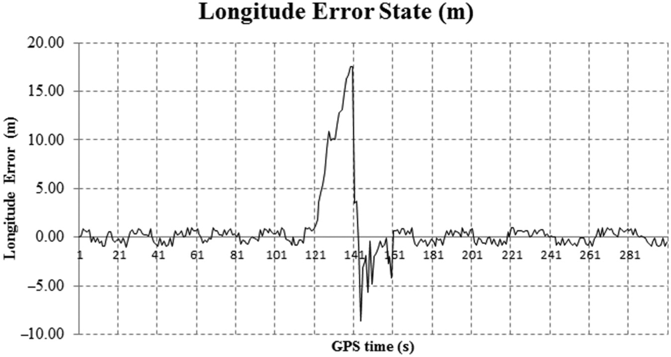
The longitude error state (y-axis) according to GPS time (x-axis) of the INS/GPS system.
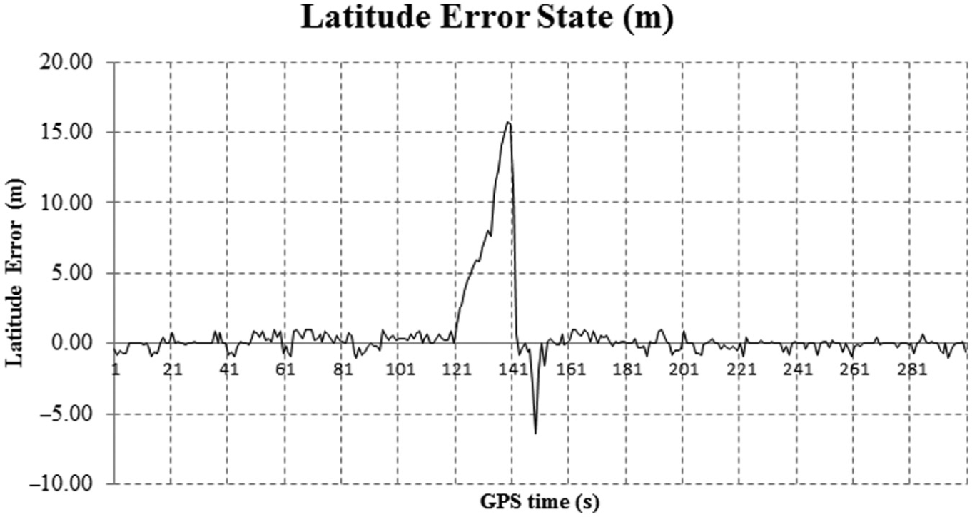
The latitude error state (y-axis) according to GPS time (x-axis) of the INS/GPS system.
When the GPS signal was lost, the INS Kalman filter predicted the position based on the state-space model. From Figure 4, after GPS outage has been simulated, the path deviated from the original trajectory without GPS outage. The deviation occurred as the IMU error was not corrected given in equations (11) and (12). From the state-space model given by equation (24), error of the state vector increased without the input of GPS position and velocity.
There was also deviation from the original path when there was no GPS outage; the deviation of the path can be attributed to the design of the priori state matrix like measurement noise covariance matrix
The results showed that the application of INS/GPS was able to produce reliable navigation solutions similar to previous loosely coupled INS/GPS Kalman filter integration.11–14 From Table 3, the root mean square (RMS) error produced by the MEMS INS/GPS system was higher than RMS error produced by tactical-grade MEMS INS/GPS system during a GPS outage. 26 The low-cost MEMS IMU was able to produce reliable navigation solutions during short interval of GPS outages which was less than 10 s. Future work for this application is to couple the INS/GPS system with a piezoelectric energy harvester under low level of vibration. 27 This application can be applied to visually impaired pedestrians navigating in alleys and nature with trees and vegetation. Limitation due to GPS outage can be overcome by coupling the device with the IMU sensors. A summary of the advantages and disadvantages of various technologies is listed as below (Table 4).
RMS error at different duration of GPS outage.

GPS: Global Positioning System; RMS: root mean square.
Comparison of various methods for visually impaired pedestrian’s navigation.

GPS: Global Positioning System; RTK: real-time kinetic; INS: Inertial Navigation System.
Conclusion
In this article, the proposed INS/GPS system was successfully implemented with reliable results. This article provided a mean for real-time implementation of a loosely coupled INS/GPS system using low-cost off-the-shelf sensors. This article used the EKF to aid INS with GPS measurements to compensate for IMU bias and to predict INS position and velocity during GPS outage. Based on Kalman filter noise behavior, the noise covariance and measurement noise matrices were determined. Real-time navigation algorithm was performed on the microcontroller. Experimental test and results were presented to validate the accuracy of the INS/GPS system. Based on this study, smart pedestrian positioning system can be developed with the integration of MEMS-based inertial sensors and GPS using existing low-cost solutions. This is especially useful for the hundreds of millions of visually impaired people worldwide, especially the lower income.
Footnotes
Appendix 1
Acknowledgements
Yong-Jin Yoon and King Ho Holden Li’s contribution is equal to that of first author.
Academic Editor: Duc T Pham
Declaration of conflicting interests
The authors declare that there is no conflict of interest.
Funding
This work was funded by the Special Disaster Emergency R&D Program from National Emergency Management Agency (2013-NEMA11-246-01010005-2013). This work was also partially supported by Nanyang Technological University under the Undergraduate Research Experience on Campus (URECA) program.