
Abstract
Binocular stereovision–based positioning and inertial measurement–based positioning have their respective limitations. Asynchronous fusion of a binocular vision system and an inertial navigation system (INS) is therefore introduced to global positioning system–denied environments with a fuzzy map. It aims to provide a sequential and progressive update with regard to mobile robot positioning and navigation. The system consists of two off-the-shelf cameras and a low-cost inertial measurement unit (IMU). The localization procedure fuses the inertial data from the IMU and the absolute position data from the binocular vision system based on corners. The main contribution of this article is a novel fusion method adaptive to different data rates at which the two modules operate. Utilization of an asynchronous Kalman filter is proposed to fuse the results from the two modules, which can achieve intermittent correction for INS localization. Experiments were carried out in an indoor laboratory environment where dynamic tests validated the reliability and effectiveness of the proposed asynchronous fusion algorithm.
Keywords
Introduction
Research on robot positioning is of great importance. It is impossible for a robot to establish a feedback regulator for motion control or navigation without positioning and orientation information. Traditional positioning methods commonly include the use of a global positioning system (GPS), 1 an odometer, 2 and/or an inertial measurement unit (IMU). 3 These key technologies can be found in autonomous navigation, 4 motion planning, 5 and simultaneous localization and mapping (SLAM). 6
As one of the popular localization methods, GPS is widely used for land vehicle positioning, although the signal propagated by a satellite may experience discontinuity and blockage caused by high-rise buildings or other obstacles. An odometer is a device for measuring the distance and speed of a vehicle. However, the scale coefficient errors of these measurements have a great and negative influence on the precision of dead reckoning. Similarly, an IMU can provide angular velocity and specific force during inertial measurement navigation, 7 and it then calculates the position and attitude information through integration. Nevertheless, an IMU is susceptible to environment noise that can lead to the drift of positioning results over time. Therefore, these traditional positioning methods cannot meet the demand of real-world applications due to systematic errors and lack of absolute precision and drift.
Recently, researchers have incorporated other sensors to complement the use of IMUs, aiming at reducing the systematic errors and improving the positioning accuracy. For example, to obtain a high-accuracy state estimate of a vehicle, a navigation system with high integrity and reliability by GPS/IMU fusion was presented. 8 In the works of Zhang and Meng, 9 a simple self-contained pedestrian tracking method using a foot-mounted inertial and a magnetic sensor module was proposed to avoid acceleration noise and integration drift. To improve the poor navigation accuracy, Zihajehzadeh et al. 10 investigated the integration of a barometric pressure sensor of microelectromechanical systems (MEMSs) with an MEMS-IMU for vertical position/velocity tracking in sports. However, the combination of these methods can only be used outdoors, and the requirement of sensors is relatively high. Fusion of vision sensors with inertial sensors thus becomes an alternative that can be applied to outdoor scenarios as well as indoor environments, owing to the fact that orientation information can be extracted from visual data of all kinds of complex environments, and will be less affected by the movement restrictions of robots. Moreover, positioning accuracy achieved by this fusion method is better than that of traditional relative positioning technologies, such as wheel-type mileage meters, inertial navigators, radars, and sonar, meaning that it is an effective alternative to the traditional positioning methods. 11 The common form of vision-aided inertial navigation systems (INSs) combines a monocular or binocular camera system with a low-cost IMU, which has been widely used in both robotics and autonomous vehicle navigation. 12 –18 Largely benefited by this method, positioning error caused by the uncertainty of visual feature extraction in the space can be reduced, the drift phenomenon can be diminished, and the accumulated error in the positioning of inertial measurement can be overcome.
In these integrated systems, the motion estimation procedure fuses the inertial data from the IMU with features (landmarks) detected in consecutive frames captured by the camera. Some methods are only used for indoor position estimation, 13 while some methods have realized SLAM with real-time monocular visual-inertial measurements. 16 Some methods are based on algorithms where INS and camera are tightly coupled to avoid loss of information possibly resulted from visual preprocessing. 17 Vision-based acquisition and estimation of subject orientation can be divided into monocular visual navigation positioning and binocular visual navigation positioning according to the number of cameras utilized. The former computes motion parameters from images acquired by a single camera, which is often uncomplicated and portable. However, it can only support 2D feature analysis and is unable to reconstruct the 3D information of the scene. 19 Depth information estimation commonly deviates due to the inaccurate estimation of camera motion parameters. Therefore, compared to the binocular vision, monocular vision is unable to provide accurate information and is only applicable to situations where depth precision is not stringently demanded. 20 In this article, position estimation of the robot is subject to accurate depth information of feature points. Therefore, we have adopted a binocular vision system to accurately reconstruct the 3D features.
Vision-aided inertial navigation methods mainly focus on using forward-looking cameras to capture salient features, which assist with navigation in man-made buildings by exploiting various features. For instance, in the work of Xian et al., 21 features both near and far from the camera are simultaneously taken into consideration in the visual-inertial method. In the work of Yu and Anastasios, 22 an algorithm for vision-aided inertial navigation is presented that employs both point and line features, which are prevalent in man-made environments. In the work of Panahandeh and Jansson, 23 to estimate the motion parameters of the system, inertial information from the IMU is integrated with the position of ground plane feature points. However, these approaches suffer in feature poor environment or scenes that contain complex backgrounds. In this article, sparse 3D features are obtained by a binocular vision system; therefore, the proposed method that combines the binocular vision system and the INS can be applied to environments where corner features are prevalent. It should be pointed out that its real-time performance is limited by the heavy computation due to what is commonly known as the “correspondence problem.” 24 Due to the trade-off between accuracy and real-time performance, this article places the focus on fast navigation when position errors are controlled within a limited range.
This article investigates the mobile robot navigation control based on visual understanding and inertial measurement of mobile robot positions in a real and complex indoor environment. Visual understanding refers to the process where a mobile robot imitates human beings to learn and perceive its surrounding environment using binocular vision sensors. In the first stage of visual understanding, scene images are captured and features extracted before positioning and navigation take place. To emulate human thinking and behaviors, the concept of fuzzy map is introduced such that a simple scene graph can be constructed in the navigation process. The fused sensory system consists of only two webcams and a low-cost IMU. The proposed approach takes advantage of the fast response of an inertial sensor and the accurate measurements of visual sensors. Consequently, the mobile robot is able to achieve rapid autonomous navigation to a particular location with the aid of a fuzzy environment map. In the experiments, the mobile robot first employs an internal fuzzy map to reach its destination, and meanwhile, the inertial measurements help it to realize indoor robot step gauge navigation. Continuously fusing the position data obtained by the binocular vision system with the location data from the IMU allows for the estimation of the current absolute position of the mobile robot and correction of inertial measurements. Data fusion methods include Kalman filters (KFs), 20 extended KFs, 12 sigma-point KFs, 17 and unscented KFs. 23 In this article, the inertial and visual modules operate at different data rates, and therefore, an asynchronous KF (AKF) is used to fuse the results from the two modules. The input of the fusion algorithm is therefore position information gained by the binocular vision system and linear acceleration vectors measured by the inertial sensor.
The main contributions of this work are: a method is put forward to achieve absolute localization for mobile robot by employing the indoor corners as natural landmarks perceived by a binocular vision system; a fusion method, which relies on an AKF such that information from inertial navigation and that from binocular vision system becomes complementary; and design of a stereo camera IMU (SC-IMU) that can be fixed on a mobile robot to allow for rapid positioning and navigation in indoor environments with further assistance from a fuzzy map.
This article is organized as follows. “Binocular vision system localization” section introduces the Harris-scale invariant feature transform (SIFT) algorithm and absolute localization of mobile robot by a binocular vision system. “Asynchronous fusion of binocular vision system and INS” section delineates the navigation updates of INS and data fusion of binocular vision and INS using an AKF. “Experiments and discussions” section specifies the SC-IMU hardware structure and verifies the practicability and accuracy of the proposed fusion algorithm. Finally, “Conclusion” section concludes this study.
Binocular vision system localization
In this article, we use a binocular vision system, which employs two webcams to recognize and extract the feature points of corners based on Harris-SIFT. It then measures the distances from cameras to feature points according to the binocular ranging technology. It finally adopts the principle of triangulation to achieve absolute localization. The process of binocular vision system localization in the indoor environments based on corners is shown in Figure 1. There are two offline phases, in which the internal and external parameters of camera are gained and feature point database built up.

The flow diagram of binocular vision system localization.
Ranging model of binocular vision system
Camera model
The binocular vision system is composed of two webcams, and the geometric relationship of cameras with respect to the target object is shown in Figure 2, where

The model of binocular camera.
The relationship between the pixel coordinates and the world coordinates can be deduced by the imaging model

where fx and fy are the component of camera focal length on the X and Y axis and (u0, v0) is the pixel coordinate of the imaging plane geometric center. These four parameters fx, fy, u0, and v0 determine the internal parameter matrix M1 of the camera. The extrinsic parameter matrix M2 is composed of the rotation matrix R and the translation vector t. Camera calibration is a process for determining the internal and external parameters. In this article, the MATLAB calibration toolbox 25 of Jean-Yves Bouguet is utilized for offline camera calibration.
Theory of binocular ranging
According to Figure 2, the distance z between target point A and the camera is calculated using the properties of similar triangles
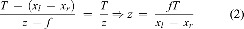
There is a linear correlation between the distance z with
Harris-SIFT algorithm
Scale invariant feature transform was summed up by Lowe,
26,27
this feature scale of image changes, image scaling, rotation, or affine transformation is invariable; however, the complex operation and slow processing speed affect the real-time performance of a binocular vision system. In the feature detection operators, the Harris corner detection algorithm is simple, stable, and relatively robust to illumination, rotation, and noise. Therefore, this article combines the advantages of SIFT feature description and Harris corner detection, that is, extracting corners by the Harris operator, and then using the SIFT operator to build feature descriptor. Finally, the similarity of the Euclidean distance metric pairs of the extracted feature points and the nearest neighbor search strategy is applied to feature matching. More specifically, these steps are as follows: (1) Detecting corners by the Harris operator
The Harris corner detection algorithm is based on signal point feature, 28 whose expression is given by

where det(M) represents the determinant of matrix M, tr(M) represents the trace of matrix, and k is the empirical value, which is 0.04. In our experiments, this value was found to produce the most reliable corner features in indoor environments where the scene images were structured and noncomplex. M is the correlation matrix. (2) Confirming feature vector of corners
The direction parameters of each feature point are specified by using the gradient direction distribution characteristics of key points in the neighborhood pixels. At each corner (x, y), the value and direction of gradient module are defined as follows
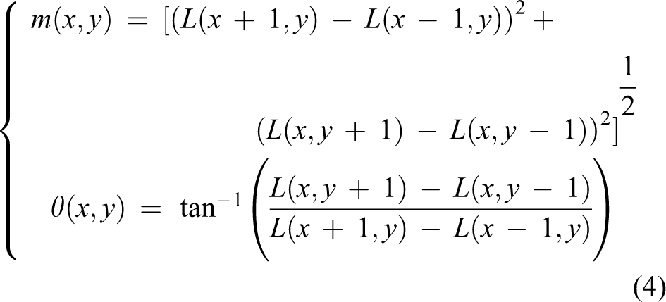
where the scale space L is defined by convolving the original image with a set of variable-scaled Gaussians.
29
(3) Calculating SIFT feature descriptor
In the computational process, in order to enhance the stability of feature matching, the relative directions of sampling points and feature points are included in histogram which contains eight directions after Gauss weighting to get a 128 (4 × 4 × 8) dimensional descriptor. 26
Offline database establishment
In this article, the keypoints extracted by the Harris corner detection algorithm are represented by SIFT descriptors, which are stored as feature vectors. All these descriptors extracted in an indoor environment are collected as natural landmarks
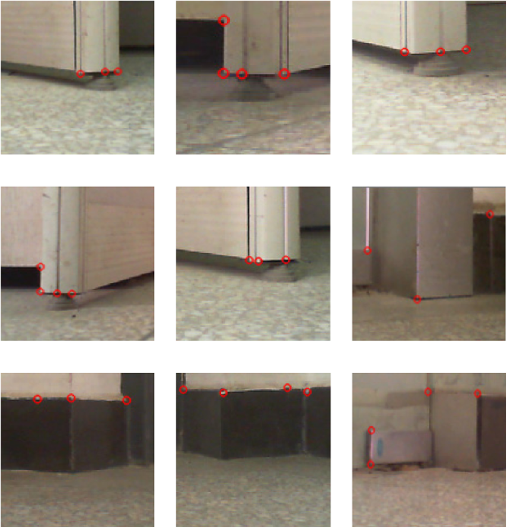
The natural landmark collection Hk.
The system acquires images periodically by the binocular vision system as the robot navigates. When a new descriptor of a corner is produced, it will be matched against those in the landmark database. If the match is successful, it is assumed that the corner is recognized. In order to apply trilateration in the world coordinate, at least three corner descriptors are required. Therefore, when the number of matched feature points is no less than 3, the match is deemed a true match, and otherwise, a false match. The system extracts the world coordinates of the corner features for a true match. It then calculates the distances between the camera and the feature points based on binocular ranging. Finally, the world coordinate of robot can be acquired according to the trilateration principle.
Asynchronous fusion of binocular vision system and INS
The schematic diagram of asynchronous fusion of binocular vision and INS is shown in Figure 4. In this article, a strap-down INS (SINS) is adopted, which is essentially an IMU (accelerometer, gyroscope, and magnetometer) rigidly mounted on the carrier. The output of the IMU is linear acceleration, angular velocity, and magnetic field. The velocity and position of the robot for each step are calculated by integrating, and the attitude update is completed by means of gradient descent. Then, according to the binocular vision algorithm utilized in this article, the absolute position of mobile robot is obtained to assist with correction for the inertial measurement. The accurate and efficient navigation process can then be achieved.

Schematic diagram of the asynchronous fusion of binocular vision and an INS. INS: inertial navigation system.
Navigation update
According to the measured values from the IMU, through coordinate transformation and navigation calculation, the position, speed, attitude, and other navigation information for robot can be obtained. The navigation process consists of three parts proposed by the strap-down algorithm. 30
Velocity update
Based on the basic equation of an INS n, the scalar form of velocity update can be directly expressed as

where Vn is the velocity, an is the acceleration in the current moment measured by an accelerometer, and ΔT is the sampling time of the INS.
Position update
Position

where
Attitude update
In the binocular vision system and INS, the measurement of them is in the body coordinate system due to the IMU being directly fixed to the robot. The direction cosine matrix (DCM)
A quaternion q is a R4 vector that can be used to represent the orientation of body coordinate relative to its navigation coordinate in R3. The quaternion consists of q0, q1, q2, and q3, whose expression is

The DCM can be expressed uniquely in terms of the quaternion

The relationship between the quaternion derivative
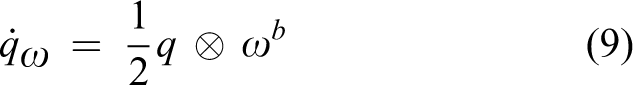
where ⊗ represents the multiplication of the quaternion. It is seen that the attitude quaternion of gyroscope qω can be obtained by integrating the quaternion derivative
In this article, the algorithm for attitude update is the gradient descent method based on quaternion. It uses the differential equation of quaternion to solve the current attitude, and then compensate the drift of gyroscope by taking advantage of the stability of accelerometer. Since the accelerometer cannot be used to sense rotations around the vertical axis, the measurement from the magnetometer is adopted to correct the orientation relative to the vertical direction. Figure 5 describes the principle of the algorithm that updates the attitudes. The attitude quaternion qω of gyroscope has been calculated by equation (9). The computational process of attitude quaternion q∇ for the accelerometer and magnetometer is introduced subsequently.

A block diagram that describes the principle of attitude update.
The objective error function is defined by 32

The magnetic field of earth can be considered to have components in one horizontal axis and vertical axis, which can be represented by
The gradient descent algorithm is adopted to calculate the attitude quaternion q∇ for the accelerometer and the magnetometer. According to the principle of gradient descent, the quaternion q∇ is given by
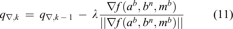
where λ is the step size and

J(q) is the Jacobian matrix of equation (10)

Then, the attitude produced by the gyroscope, accelerometer, and magnetometer can be fused according to the following equation

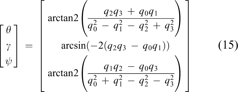
In the final step of the attitude update procedure, it is necessary to normalize the resultant quaternion q e,k , and therefore, the calculated integrator may not be a unit quaternion. The attitude, which included pitch θ, roll γ, and yaw ψ, can be written as the following identity 33
Data fusion based on the AKF algorithm
INS is a kind of autonomous navigation systems. Various navigation parameters could be computed in real time according to the specific force and angular rate measured in the IMU as long as the initial condition of navigation system is provided. When the position of robot is calculated by integration, the drift of position information can be caused by the error of acceleration values, which can cause the navigation to fail. Therefore, this article adds binocular vision to the system in order that the robot can carry out phase correction, which overcomes the disadvantages of a low-cost IMU.
In order to improve the navigation accuracy of the integrated binocular vision system and INS, an AKF for data fusion is designed. It fuses the current robot position acquired by the IMU and absolute localization from the binocular vision system, and therefore can achieve intermittent correction for the localization of INS. In the integrated navigation system, an AKF is used to adaptively adjust the motion state of the robot. An AKF is uncomplicated and hence improves the system efficiency.
For a KF to be applicable, the state vector of the target at time instant k is defined as

Namely the state space model of this system is

where A is the time-invariant state transition matrix, uk − 1uk − 1 is the acceleration of mobile robot in the current moment measured by the accelerometer, and wk − 1 is a white noise sequence with its covariance matrix Qk − 1 representing the process noise.
A linear model for this measurement can be given by

where zk is the observation vector containing the position in the time instant k, which is measured by binocular vision system,
A block diagram that illustrates the principle of the proposed KF is summarized in Figure 6. It can be seen that the KF includes the time update (projection) and the state update (rectification) aspects. The projection equation reflects the change in the estimation value

Block diagram of the proposed KF. KF: Kalman filter.
In the experiment, the measurement period is large and the dynamic of the system is changing rapidly. Therefore, this article treats the computation period of these two kinds of equations differently. Assuming that the correction period is T, which is divided into N short period

where ΔT is the step of solving the prediction equation. A sampling schematic diagram of the AKF based on vision-aided inertial navigation is shown in Figure 7. The prediction calculation of the INS is at

Sampling schematic diagram of AKF. AKF: asynchronous Kalman filter.
Experiments and discussions
In order to evaluate the performance of the proposed algorithm, extensive tests have been performed practically. In this section, we introduce the SC-IMU hardware design, preparation for the experiments, as well as analysis of the positioning experimental results.
SC-IMU hardware design
In the binocular vision system and the INS, the two cameras are rigidly attached to the front of the mobile robot. The IMU controller is placed at the center of robot such that the navigation coordinate system is in accordance with the body coordinate system. It consists of the ST-Microelectronics STM32F103 (ARM Cortex-M3 32-bit CPU) and an IMU module (including a tri-axis magnetometer HMC5883L, and the MPU6050 embedded with a tri-axis MEMS gyroscope and a tri-axis MEMS accelerometer). The size of IMU module is 16 × 21 mm2, which is shown in Figure 8(d). The binocular camera system and the IMU controller are directly connected to a laptop via a Universal Serial Bus (USB) port.

The cameras used in the binocular vision system and the IMU controller for positioning and navigation. (a) Mobile robot in the experiment. (b) The cameras used in the binocular vision system. (c) The IMU controller. (d) The IMU module. IMU: inertial measurement unit.
The binocular system comprises of two webcams whose model is LifeCam HD-3000 with a resolution of 720 × 640 pixels. They are 55 mm apart and 740 mm off the ground. The MEMS gyroscope can function in four different ranges with a maximum of ±2000° s−1 output, which is sufficient to sense the motion of high-speed rotation. The MEMS accelerometer can also functions at four different ranges with a maximum of ±2g output. In the experiment, the specifications of IMU module are shown in Table 1.
IMU module measured specifications.

IMU: inertial measurement unit; Acc: accelerometer; Gyro: gyroscope; Mag: magnetometer.
Preparation of experiment
In this article, a feasible scheme of rapid positioning and navigation based on inertial measurements and binocular vision system is proposed by introducing fuzzy map into the mobile robot platform. This has been implemented and tested using Microsoft Visual Studio 2010. As shown in Figure 9, two fuzzy maps of indoor environment with a predefined path are designed, which contains a number of corners (solid black spot) whose world coordinates are known. The dashed line represents the path, following which the robot navigates to the destination in the absence of obstacles. In the process of navigating to the destination, the mobile robot follows a circulatory navigation control mode of inertial measurement, visual correction, and inertial measurement, namely: Determining the initial position of the mobile robot in the fuzzy map using IMU to position at the beginning of the experiment. Detecting and recognizing corners based on Harris-SIFT in a fuzzy map by employing the binocular vision system to calculate the position of robot according to the proposed estimation algorithm. The inertial measurement of position is fused using an AKF to modify the position of the mobile robot. Positioning and navigating of the mobile robot using the inertial measurement sequentially, that is, executing steps (2) and (3) circularly until it reaches the destination.
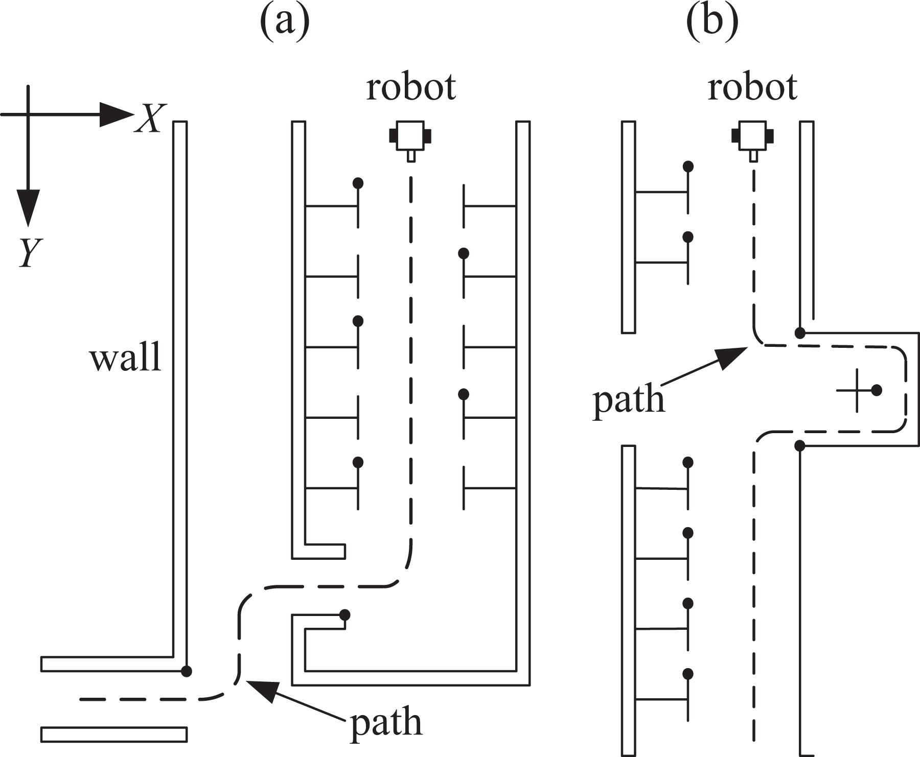
The fuzzy map of indoor environment with predefined path.
Before the mobile robot localization and navigation experiment, two groups of experiments had been carried out to test the performance of the binocular vision system and the IMU as follows.
Experiment 1: The mobile robot follows a straight line of 4.2 m in the interior corridor and calculates its attitude according to the gradient descent method. The error of location results is defined as

where

The short-distance experiment results. (a) Location results of IMU. (b) Positioning error. IMU: inertial measurement unit.
Experiment 2: In order to test the accuracy of positioning by the binocular vision system proposed in this article, we selected several certain points in the experimental environment and measured the 3D coordinates of points in millimeters relative to the camera by hand, as shown in Table 2. It can be seen that the positioning accuracy of binocular vision can meet the experimental requirements and can be used to correct the position of the INS.
Binocular measurement result and position error (mm).

Real experiment and analysis
A two-wheel mobile robot equipped with the SC-IMU hardware module designed in this article was used as the experiment platform to collect data on line. Two dynamic indoor experiments were conducted on the sixth floor and the first floor of the laboratory, respectively, to validate the reliability and effectiveness of the proposed algorithm. This experiment presents a fusion of vision and inertial navigation in a GPS-denied condition. The vision information was fused at 1 Hz (i.e. vision information was employed for correction every second) on average and the output frequency of IMU is a fixed 125 Hz. We performed many tests where the mobile robot navigated in indoor environments along a predefined path. To illustrate the results of this experiment intuitively, following trajectories are given: truth-value, INS, and fusion of binocular vision and INS.
Results of experiment 1 are shown in Figure 11, which corresponds to the predefined path in Figure 9(a). The route length of experiments is 32.5 m. The test process of this indoor experiment is shown in Figure 12. The estimated trajectory obtained by data fusion using the AKF algorithm is compared with the trajectory obtained by INS alone, the pure vision, and the measured ground truth. It can be seen that the red trajectory of the integrated system is the closest to the true path, and the positioning errors of the blue trajectory from INS alone are larger than the red trajectory from the integrated system. Figure 13 shows the velocity estimates that compare the integrated system with pure INS. The results prove that the proposed algorithm can improve the positioning accuracy of a mobile robot and can limit its velocity within a certain range.

The results of dynamic indoor experiments, which corresponds to the predefined path in Figure 9(a). (a) Comparison of the estimated trajectories between the proposed fusion algorithm, INS, and truth-value. (b) Comparison of positioning errors between the proposed fusion algorithm and INS. INS: inertial navigation system.

The test process of experiment in the indoor environment.

Comparison of the estimated velocities, which corresponds to the predefined path in Figure 9(a). (a) x-direction velocity of the proposed fusion algorithm and INS. (b) y-direction velocity of the proposed fusion algorithm and INS. INS: inertial navigation system.
To demonstrate the utility of the proposed fusion method, trajectories estimated by standard KF and AKF are summarized in Figure 14. It is observed from Figure 14(b) that the proposed AKF has a higher positioning accuracy than standard KF.

Comparison experiments between standard KF and the proposed AKF algorithm. (a) Trajectories estimated by standard KF and the proposed AKF algorithm. (b) Comparison of positioning errors.
Experimental results for another predefined path are shown in Figure 15, which corresponds to Figure 9(b). The route length of this experiment is 66.5 m. As expected, the positioning result of the mobile robot by the fusion of binocular vision system and INS shows a negligible deviation, as shown in Figure 15(b). The comparative evaluation shows that the proposed method can regulate the output from a pure INS-based method. While INS will very likely lead to the “drifting” problem, the proposed method can recover from large positioning errors and decrease them by data association. Figure 16 shows the velocity estimates which compare the integrated system with pure INS. This again proves that the integrated system can serve to improve the accuracy of localization.

The results of dynamic indoor experiments, which corresponds to the predefined path in Figure 9(b). (a) Comparison of the estimated trajectories between the proposed fusion algorithm, INS, and truth-value. (b) Comparison of the positioning errors between the proposed fusion algorithm and INS. INS: inertial navigation system.

Comparison of estimated velocities, which corresponds to the predefined path in Figure 9(b). (a) x-direction velocity of the proposed fusion algorithm and INS. (b) y-direction velocity of the proposed fusion algorithm and INS. INS: inertial navigation system.
To illustrate the utility of the proposed AKF, another comparison test between standard KF and the proposed method is shown in Figure 17. It can be seen that the positioning error of red from AKF is smaller, and this again proves the efficiency of the proposed fusion method.

Comparison experiments between standard KF and the proposed AKF algorithm. (a) Trajectories estimated by standard KF and the proposed AKF algorithm. (b) Comparison of positioning errors. KF: asynchronous Kalman filter; AKF: asynchronous KF.
To demonstrate the rapidity of the proposed navigation method, another trial has been conducted in comparison with the employment of a stereo visual odometry (VO), as shown in Figure 18. It can be seen that the positioning error of the fusion of binocular vision and INS is larger than that of VO; however, the navigation time of the proposed method is much shorter. The results prove that the proposed algorithm can realize fast navigation.

The results of comparison experiments. (a) Comparison of the estimated trajectories between the proposed fusion algorithm, VO, and truth-value. (b) Positioning error of the proposed fusion algorithm. (c) Positioning error of VO. VO: visual odometry.
Conclusion
This article presents a real-time system that integrates binocular vision and INS for positioning the control of a mobile robot, which can operate reliably in indoor environments. We propose an algorithm for the estimation of absolute robot positions based on a dedicated and integrated sensory system. The SC-IMU hardware is specifically designed for the system and enables it to acquire data via a combination of an accelerometer, a gyroscope, and a magnetometer. An AKF is proposed to fuse the information from inertial navigation and the data from the binocular vision system, which can mitigate errors by suppressing the drift of inertial measurements. Three dynamic indoor experiments were conducted to validate the reliability and effectiveness of the proposed algorithm. Compared with pure INS and VO, the results indicate that the proposed fusion method can significantly improve the positioning accuracy and can achieve fast navigation. It should be noted that although the proposed system can achieve high accuracy in most indoor environments, limiting factors such as no-stationary obstacles cannot be resolved which therefore remain to be investigated in our further study.
Footnotes
Declaration of conflicting interests
The author(s) declared no potential conflicts of interest with respect to the research, authorship, and/or publication of this article.
Funding
The author(s) disclosed receipt of the following financial support for the research, authorship and/or publication of this article: This work is supported by four Projects from National Natural Science Foundation of China (60705035, 61075087, 61573263, 61273188), Scientific Research Plan Key Project of Hubei Provincial Department of Education (D20131105), Project supported by the Zhejiang Open Foundation of the Most Important Subjects, and supported by Science and Technology support plan of Hubei Province (2015BAA018), also supported by Zhejiang Provincial Natural Science Foundation (LY16F030007).