This article deals with the methodology of the kinematic and rigid-body dynamic performance evaluation of the 3UPS-PRU (the underlined P denotes an actuating prismatic joint) parallel robot. The maximum input velocity index, the maximum driving torque index, and the maximum driving power index are formulated based on kinematic and rigid-body dynamic model, the theory of matrix norm and inequality. The physical meanings of the indices are the maximum input velocity, the maximum driving torque, and the maximum driving power, respectively, when the moving platform translates along the z-axis in the maximum linear acceleration amax, rotates about an arbitrary axis in the maximum angular acceleration αmax, translates along the z-axis in the maximum linear velocity vmax, and rotates about an arbitrary axis in the maximum angular velocity . Employing the worst-case criterion, the example of the kinematic and rigid-body dynamic performance evaluation of the 3UPS-PRU parallel robot is carried out using the presented indices. It is shown that the distribution trends of the maximum driving torque and the maximum driving power are roughly the same for the 3UPS-PRU parallel robot. The conclusions are provided at the end of the article.
Parallel robots have been successfully used in pick-and-place operation with high speed or high acceleration,1–3 motion simulator with heavy load,4–6 machine tool with high-precision requirement,7–9 and so on. Structure optimization, trajectory planning, and state measurement and control should be carried out in order to achieve an excellent performance. The performance evaluation can provide a reference standard for the above-mentioned work. The performance index can be used in the structure optimization and trajectory planning as the objective function or the constraint function. The performance evaluation for the parallel robot is the issue worthy of study.
Performance evaluation of a parallel robot can be implemented through experimental testing, software simulation, and theoretical computation. There are respective advantages for the above-mentioned technique. Performance evaluation through theoretical computation can provide a general evaluation methodology and a reference to the design for the parallel robots. Many investigations have been carried out on the kinematic performance evaluation and the rigid-body dynamic performance evaluation. The criteria used for the kinematic performance evaluation of the parallel robots are usually isotropy,10–13 manipulability,14,15 transmission,16,17 work space,10,18–22 singularity,17,20–22 and so on. Due to the generalized dual relationship between kinematics and statics, some kinematic performance indices can be redefined and used for the evaluation of static property. The definitions of some kinematic performance indices are based on the Jacobian matrices. The Jacobian matrix represents the linear relationship between the velocity vector of the moving platform and the joint velocity vector. The Jacobian matrix will be amplified in equal proportion if the parallel robot is amplified. This will bring difficult for performance evaluation through the kinematic performance index whose definition is based on the Jacobian matrix. For the parallel robot with symmetrical structure, the kinematic performance index may take no effect when the end effector is on the centerline of the work space.17 The criteria used for the rigid-body dynamic performance evaluation of the parallel robots are usually balance,23–25 dynamic isotropy,26,27 torque index,3,28–31 power index,3,30,31 natural frequency,2,28,32 dynamic response,33 power requirement,14,31,34,35 energy efficiency,36–39 and so on. Zhao3,31 introduced a torque index and a power index considering the acceleration component of torque, the velocity component of torque, and the gravity component of torque in the rigid-body dynamic model. In addition, stiffness criteria40–43 and accuracy criteria44–48 are also used for the performance evaluation or design of the parallel robots. Performance evaluation of a parallel robot is a multi-criteria problem. There is no index that can evaluate the performance of the parallel robot from all standpoints.17 For a specific parallel robot, the performance evaluation should be carried out by adopting the appropriate index while considering the application. The studied 3UPS-PRU parallel mechanism is used to build a hyper-redundant robot. The maximum linear velocity, the maximum angular velocity, the maximum linear acceleration, and the maximum angular acceleration should be considered simultaneously in the performance evaluation in order to achieve an excellent kinematic and rigid-body dynamic characteristic.
The aim of this article is to present a work on the kinematic and rigid-body dynamic performance evaluation of a 3UPS-PRU parallel robot. The maximum input velocity index, the maximum driving torque index, and the maximum driving power index are presented by the theory of matrix norm and inequality. The kinematic and rigid-body dynamic performance evaluation of the 3UPS-PRU parallel robot has been carried out by using the presented indices.
The article is organized as follows: The 3UPS-PRU parallel robot is explained in the second section. The kinematic and rigid-body dynamic model is provided in the third section. Performance evaluation of the 3UPS-PRU parallel robot is investigated in the fourth section. Example is illustrated in the fifth section. The final section gives the conclusions.
3UPS-PRU parallel robot
The 3UPS-PRU parallel robot is shown in Figure 1. The parallel robot is composed of a base platform connected with the moving platform through three external identical UPS limbs and one central PRU limb. All the limbs are driven by the prismatic joint. The central PRU limb is fixed on the base platform. Here, the P, R, U, and S represent, respectively, a prismatic, revolute, universal, and spherical joint. The underlined P denotes an actuating prismatic joint driven by a servomotor. There are three rotational and one translational degrees of freedom for the moving platform due to the proper constraints of the central limb and the three external limbs.
The UPS-PRU parallel robot.
In order to set up the rigid-body dynamic model, the following coordinate systems are defined as shown in Figure 1. The reference coordinate system is attached to the center of the base platform, and the moving coordinate system is located at the centroid of the moving platform. The orientation of the moving platform can be described by a rotation matrix that can be defined by the parameters of roll, pitch, and yaw angle, namely, a rotation of φx about the fixed x-axis, a rotation φy about the fixed y-axis, and a rotation φz about the fixed z-axis. Thus, the rotation matrix is
The angular velocity and acceleration of the moving platform are given by49
The local coordinate system associated with the ith limb is defined and shown in Figure 2 for the convenience of the rigid-body dynamic formulation. The orientation of the local coordinate system with respect to the reference coordinate system can be described by two angles. It can be thought of as a rotation of φi about z-axis resulting in a coordinate system followed by another rotation of ϕi about the rotated axis. So the rotation matrix can be expressed as
The local coordinate system of the ith limb.
The unit vector along the ith limb in the coordinate system is
So the angles φi and ϕi can be computed as follows
Kinematic and rigid-body dynamic model
Position analysis
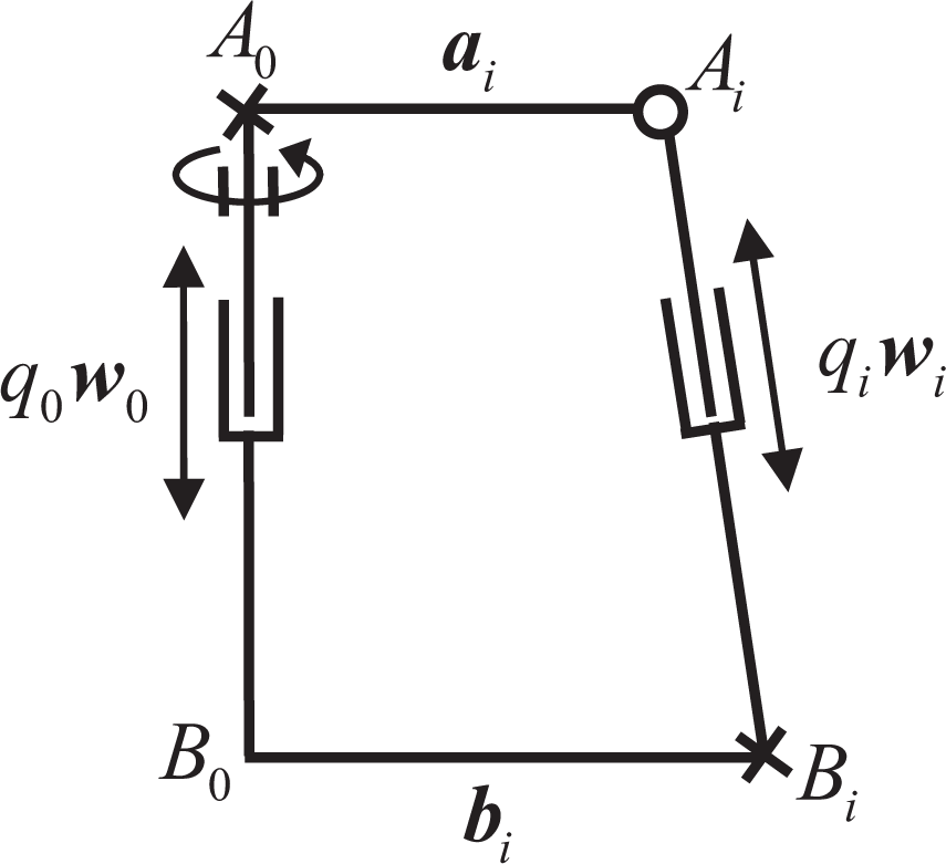
As shown in Figure 3, the closed-loop vector equation associated with the ith limb can be obtained as
Vector diagram of the ith limb.
where represent the joint variables of the ith limb and the central limb, the unit vectors along the ith limb and the central limb, the vector , and the vector , respectively.
The joint variable of the ith actuating joint can be obtained by taking norms on both sides of equation (7)
Velocity and acceleration of the actuating joint
Taking the derivative of equation (7) with respect to time and then taking the dot product of both sides with wi, we obtain the relationship between the velocity vector of the actuating joint and the velocity vector of the moving platform
where
J is the Jacobian matrix, denote the velocity vector, the linear velocity, and the angular velocity vector of the moving platform, respectively.
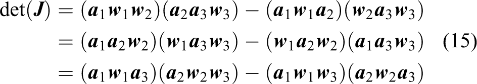
From equation (13), the determinant of Jacobian matrix can be obtained as
The determinant of Jacobian matrix can be achieved by utilizing the theorem of vector operation
where (⋅) is the mixed product of vectors. If the three free vectors are in the same plane, the mixed product of vectors equals to 0.
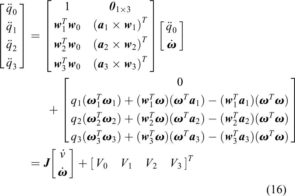
Taking the derivative of equation (7) twice with respect to time, taking the dot product of both sides with wi, and then writing in the matrix form, we get the acceleration of the actuating joint
where
and ω denote the acceleration along the central limb and the angular acceleration vector of the moving platform, respectively.
Velocity and acceleration of the kinematic limb
The angular velocity of the ith limb described in the coordinate system can be achieved by taking the derivative of equation (7) with respect to time, taking the cross product of both sides with , and substituting into it
where is the screw matrix and is the link Jacobian matrix which maps the velocity vector of the moving platform in the task space into the angular velocity of the ith limb described in the coordinate system . Since the central limb is fixed on the base platform, there is only telescopic movement, so we can get
The linear velocity of the center of mass ci1 in the ith limb can be described in the coordinate system as
where
The central limb is fixed on the base platform, so the linear velocity of the center of mass c01 is 0, and
The linear velocity of the center of mass ci2 can be described in the coordinate system as
where
is the link Jacobian matrix which maps the velocity vector of the moving platform in the task space into the linear velocity vector of the center of mass ci2. For the central limb, there is only telescopic movement, we get
The angular acceleration of the ith limb described in the coordinate system can be achieved by taking the derivative of equation (7) twice with respect to time and substituting into it
where is the angular acceleration vector of the moving platform. For the central limb, the angular acceleration is .
Taking the derivative of equation (22) with respect to time, substituting equation (28) into it and describing the result in the coordinate system , we get the linear acceleration of the center of mass ci1 in the ith limb
For the central limb, the linear acceleration is .
Taking the derivative of equation (25) with respect to time, substituting equation (28) into it and describing the result in the coordinate system , we obtain the linear acceleration of the center of mass ci2 in the ith limb
There is only telescopic motion for the central limb, so the linear acceleration of the center mass c02 is
Driving torque
From the D’Alembert’s principle, the resultant of applied and inertia forces exerted at the center of mass of each inertia component of the 3UPS-PRU parallel robot can be obtained when the linear acceleration, angular velocity, and angular acceleration are known. The rigid-body dynamic model can be set up by the principle of virtual work and the concept of link Jacobian matrix. The driving torque can be achieved as
where are the total driving torque and the driving torques related to the acceleration, velocity, gravity, and external force components, respectively. And
is the generalized inertia matrix which maps the acceleration of the moving platform into the driving torque.
Driving power
The required driving power of the ith actuating joint can be obtained by
where are the respective driving powers of the ith actuating joint related to the acceleration component of torque, velocity component of torque, gravity component of torque, and external force component of torque.
Performance evaluation
Velocity transmission index
From equations (9) and (13), the maximum input velocity of the actuating joint can be obtained when the moving platform translates along z-axis with the maximum linear velocity vmax
where is infinite norm of the vector.
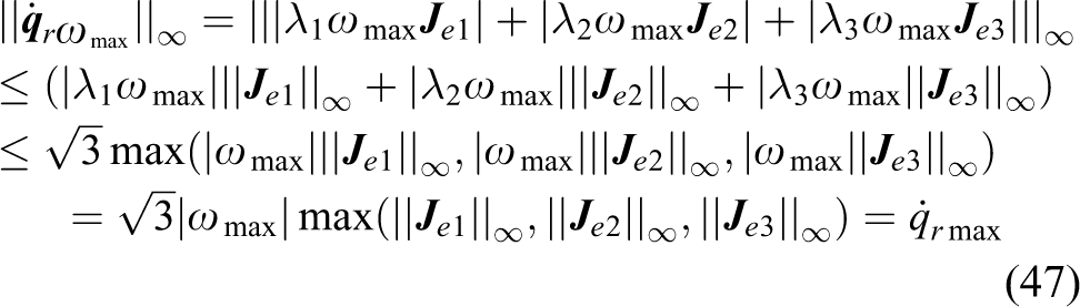
When the moving platform rotates about x-, y-, and z-axes in the maximum angular velocity , respectively, the maximum input velocities of the actuating joints are
When the moving platform rotates about an arbitrary axis in the maximum angular velocity ωmax, it can be described as
where
From the theory of matrix norm and inequality, the maximum input velocity of the actuating joint can be obtained when the moving platform rotates in the maximum angular velocity ωmax
where |⋅| is the absolute value.
When the maximum linear velocity and the maximum angular velocity of the moving platform are vmax and ωmax, respectively, the maximum input velocity of the actuating joint can be obtained as
Driving torque index
Driving torques related to the acceleration
From equation (33), the driving torque related to the acceleration can be obtained when the moving platform translates along or rotates about the axes in the unit acceleration
where
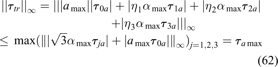
When the moving platform translates along the z-axis in the maximum linear acceleration amax, the maximum driving torque related to the acceleration is
When the moving platform rotates about the x-, y-, and z-axes in the maximum angular acceleration , respectively, the maximum driving torques related to the acceleration can be obtained as
If the moving platform rotates about an arbitrary axis in the maximum angular acceleration αmax, then the acceleration can be expressed as
where
From the theory of matrix norm and inequality, the maximum driving torque related to the acceleration can be achieved when the moving platform rotates about an arbitrary axis in the maximum angular acceleration αmax
When the moving platform translates along the z-axis in the maximum linear acceleration amax and rotates about an arbitrary axis in the maximum angular acceleration αmax, the probable maximum driving torque related to the acceleration can be achieved as
Driving torques related to the velocity
From equation (33), when the moving platform translates along the z-axis or rotates about the x-, y-, and z-axes in the unit velocity, respectively, the driving torques related to the velocity can be obtained
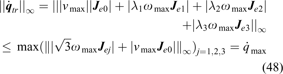
When the moving platform translates along the z-axis in the maximum linear velocity vmax, the maximum driving torque related to the velocity is
When the moving platform rotates about the x-, y-, and z-axes in the maximum angular velocity , respectively, the maximum driving torques related to the velocity can be obtained as
If the moving platform rotates about an arbitrary axis in the maximum angular velocity ωmax, the probable maximum driving torque related to the velocity can be achieved as
When the moving platform translates along the z-axis in the maximum linear velocity vmax and rotates about an arbitrary axis in the maximum angular velocity , the probable maximum driving torque related to the velocity can be obtained by
Driving torques related to the gravity
When the moving platform translates or rotates in the work space, the driving torques related to the gravity can be obtained from equation (33)
Driving torques related to the external forces
When the moving platform translates or rotates in the work space, the driving torques related to the external forces can be obtained from equation (33)
The studied 3UPS-PRU parallel robot is not used for machining operation, the external forces are not considered since the relationship between the external forces and the driving torques is simple.
The maximum driving torque
When the moving platform translates along the z-axis in the maximum linear acceleration amax, rotates about an arbitrary axis in the maximum angular acceleration αmax, translates along the z-axis in the maximum linear velocity vmax, and rotates about an arbitrary axis in the maximum angular velocity , the probable maximum driving torque can be achieved as
It is taken as the driving torque index. The maximum driving torque index should be as small as possible to achieve the best input torque characteristic.
Driving power index
When the moving platform translates along the z-axis in the maximum linear acceleration amax, rotates about an arbitrary axis in the maximum angular acceleration αmax, translates along the z-axis in the maximum linear velocity vmax, and rotates about an arbitrary axis in the maximum angular velocity , the probable maximum driving power can be achieved as
It is taken as the driving power index. The maximum driving power index should be as small as possible to achieve the best input power characteristic. It should be pointed out that the extreme case criterion is employed in this investigation to evaluate the dynamic performance of the parallel robot since the maximum acceleration and the maximum velocity only occurs in the worst case.
Example
A numerical example is presented in this section. The parameters of the 3UPS-PRU parallel robot are given in Tables 1 to 4. The distance between the rotation center and the center of mass of the moving platform is .
The parameters of the base platform (m).
0
1
2
3
xBi
0.000000
0.200000
−0.100000
−0.100000
yBi
0.000000
0.000000
0.173205
−0.173205
zBi
0.000000
0.000000
0.000000
0.000000
The parameters of the moving platform measured in the coordinate system (m).
0
1
2
3
xAi
0.000000
−0.175000
−0.087500
−0.087500
yAi
0.000000
0.000000
0.151554
−0.151554
zAi
0.000000
0.000000
0.000000
0.000000
The length of the struts connected, respectively, with the moving platform and the base platform (m).
0
1
2
3
lai
0.300000
0.300000
0.300000
0.300000
lbi
0.300000
0.300000
0.300000
0.300000
The mass of the moving platform and the struts connected, respectively, with the moving platform and the base platform (kg).
mi
2.597704
0.145047
0.099243
When the moving platform translates along the z-axis in the maximum linear acceleration , rotates about an arbitrary axis in the maximum angular acceleration , translates along the z-axis in the maximum linear velocity , and rotates about an arbitrary axis in the maximum angular velocity , the distributions of the maximum input velocity, the maximum driving torque, and the maximum driving power of the actuating joint are shown in Figure 4. The orientation of the moving platform is . The middle layer, the upper layer, and the bottom layer correspond to the cases , respectively.
The distributions of the maximum input velocity (A), the maximum driving torque (B), and the maximum driving power (C) of the actuating joint.
It is shown that the distribution trends of the maximum driving torque and the maximum driving power are roughly the same. It implies that the results are the same when taking the maximum driving torque and the maximum driving power as the objective functions for the structure optimization and trajectory planning. The maximum input velocity, the maximum driving torque, and the maximum driving power when the moving platform is on the bottom layer are smaller than those when the moving platform is on the upper layer. It means that the kinematic and rigid-body dynamic performance measured from the point of the input velocity, the driving torque, and the driving power is best when the moving platform is on the bottom layer. This can help us to select the central position of the workspace when the structure parameters of the parallel mechanism are assigned.
Conclusions
The performance evaluation of the 3UPS-PRU parallel robot is presented in this article. The following conclusions can be drawn:
The maximum input velocity index, the maximum driving torque index, and the maximum driving power index are presented by the theory of matrix norm and inequality. The physical meanings of the indices are the maximum input velocity, the maximum driving torque, and the maximum driving power, respectively, when the moving platform translates along the z-axis in the maximum linear acceleration amax, rotates about an arbitrary axis in the maximum angular acceleration αmax, translates along the z-axis in the maximum linear velocity vmax, and rotates about an arbitrary axis in the maximum angular velocity .
The kinematic and rigid-body dynamic performance evaluation of the 3UPS-PRU parallel robot has been carried out using the presented indices. It is shown that the distribution trends of the maximum driving torque and the maximum driving power are roughly the same for the 3UPS-PRU parallel robot. It implies that the results are the same when taking the maximum driving torque and the maximum driving power as the objective functions for the structure optimization and trajectory planning. For the simulation, the kinematic and rigid-body dynamic performance measured from the point of the input velocity, the driving torque, and the driving power is best when the moving platform is on the bottom layer. This will also help us to select the central position of the work space when the structure parameters of the parallel mechanism are assigned.
Footnotes
Acknowledgments
The authors would also like to thank the anonymous reviewers for their very useful comments.
Declaration of conflicting interests
The author(s) declared no potential conflicts of interest with respect to the research, authorship, and/or publication of this article.
Funding
The author(s) disclosed receipt of the following financial support for the research, authorship, and/or publication of this article: This research is jointly sponsored by the National Natural Science Foundation of China (Grant No. 51375288), the Science and Technology Program of Guangdong Province (Grant No. 2015B090906001), and the Special Research Foundation of Discipline Construction of Guangdong Province (Grant No. 2013KJCX0075).
References
1.
StaicuS. Recursive modelling in dynamics of Delta parallel robot. Robotica2009; 27(2): 199–207.
2.
LiHHYangZYHuangT. Dynamics and elasto-dynamics optimization of a 2-DOF planar parallel pick-and-place robot with flexible links. Struct Multidiscip Optim2009; 38(2): 195–204.
3.
ZhaoYJ. Dynamic performance evaluation of a three translational degrees of freedom parallel robot. Int J Robot Autom2012; 27(1): 31–40.
4.
DongWDuZJXiaoYQ. Development of a parallel kinematic motion simulator platform. Mechatronics2013; 23(1):154–161.
5.
ZhaoYJGaoFLiWM. Development of 6-DOF parallel seismic simulator with novel redundant actuation. Mechatronics2009; 19(3): 422–427.
6.
ChengGLiYFengLL. Configuration bifurcation and self-motion analysis of 3SPS + 1PS bionic parallel test platform for hip joint simulator. Mech Mach Theory2015; 86: 62–72.
7.
CaccavaleFSicilianoBVillaniL. The tricept robot: dynamics and impedance control. IEEE/ASME Trans Mech2003; 8(2): 263–268.
8.
LiMHuangTMeiJP. Dynamic formulation and performance comparison of the 3-DOF modules of two reconfigurable PKM—the tricept and the trivariant. ASME J Mech Des2005; 127(6): 1129–1136.
9.
ZhangDGosselinCM. Kinetostatic analysis and design optimization of the tricept machine tool family. ASME J Manuf Sci Eng2002; 124(3): 725–733.
10.
Rao KoteswaraABRaoPVMSahaSK. Dimensional design of hexaslides for optimal workspace and dexterity. IEEE Trans Robot2005; 21(3): 444–449.
11.
HuangTLiZXLiM. Conceptual design and dimensional synthesis of a novel 2-DOF translational parallel robot for pick-and-place operations. ASME J Mech Des2004; 126(3): 449–455.
12.
GosselinCMAngelesJ. A global performance index for the kinematic optimization of robotic manipulators. ASME J Mech Des1991; 113(3): 220–226.
13.
HuangTLiMLiZX. Optimal kinematic design of 2-DOF parallel manipulators with well-shaped workspace bounded by a specified conditioning index. IEEE Trans Robot Autom2004; 20(3): 538–543.
14.
MansouriIOualiM. The power manipulability–a new homogeneous performance index of robot manipulators. Robot Comput-Int Manuf2011; 27(2): 434–449.
15.
HongKSKimJG. Manipulability analysis of a parallel machine tool: application to optimal link length design. J Robot Syst2000; 17(8): 403–415.
16.
LiuXJWangLPXieFG. Design of a three-axis articulated tool head with parallel kinematics achieving desired motion/force transmission characteristics. ASME J Manuf Sci Eng2010; 132(2): 021009-1–021009-8.
17.
ZhaoYJ. Singularity, isotropy and velocity transmission evaluation of a three translational degrees of freedom parallel robot. Robotica2013; 31(2): 193–202.
18.
LaribiMARomdhaneLZeghloulS. Analysis and dimensional synthesis of the DELTA robot for a prescribed workspace. Mech Mach Theory2007; 42(7): 859–870.
19.
MillerK. Maximization of workspace volume of 3-DOF spatial parallel manipulators. ASME J Mech Des2002; 124(2): 347–357.
20.
YangYWO’BrienJF. A sequential method for the singularity-free workspace design of a three legged parallel robot. Mech Mach Theory2010; 45(11): 1694–1706.
21.
LiHDGosselinCMRichardMJ. Determination of the maximal singularity-free zones in the six-dimensional workspace of the general Gough–Stewart platform. Mech Mach Theory2007; 42(4): 497–511.
22.
LiuXJWangJSOhKK. A new approach to the design of a DELTA robot with a desired workspace. J Intell Robot Syst2004; 39(2): 209–225.
AliciGShirinzadehB. Optimum dynamic balancing of planar parallel manipulators based on sensitivity analysis. Mech Mach Theory2006; 41(12): 1520–1532.
25.
IliaDSinatraR. A novel formulation of the dynamic balancing of five-bar linkages with applications to link optimization. Multibody Syst Dyn2009; 21(2):193–211.
26.
MaOAngelesJ. Optimum design of manipulators under dynamic isotropy conditions. In: Proceedings of the IEEE international conference on robotics and automation, Atlanta, USA, 2–6 May 1993, pp. 470–475. DOI: 10.1109/ROBOT.1993.292024.
27.
TongZZHeJFJiangHZ. Optimal design of a class of generalized symmetric Gough–Stewart parallel manipulators with dynamic isotropy and singularity-free workspace. Robotica2012; 30(2): 305–314.
28.
ZhaoYJ. Dynamic design theory and methodology of the high-speed and light-weight parallel robot(in Chinese). PhD Dissertation, Tianjin University, China, 2006.
29.
ZhangLMMeiJPZhaoXM. Dimensional synthesis of the Delta robot using transmission angle constraints. Robotica2012; 30(3): 343–349.
30.
ZhaoYJ. Dynamic optimum design of a three translational degrees of freedom parallel robot while considering anisotropic property. Robot Comput-Int Manuf2013; 29(4): 100–112.
31.
ZhaoYJGaoF. The joint velocity, torque and power capability evaluation of a redundant parallel manipulator. Robotica2011; 29(3): 483–493.
32.
KozakKEbert-UphoffIVoglewedePA. Concept paper: on the significance of the lowest linearized natural frequency of a parallel manipulator as a performance measure for concurrent design. In: Proceedings of the WORKSHOP on fundamental issues and future research directions for parallel mechanisms and manipulators (GosselinClement M.ImmeEbert-Uphoff, eds), Quebec, Canada, 3–4 October 2002, pp. 112–118.
33.
da SilvaMMde OliveiraLPRBrülsO. Integrating structural and input design of a 2-DOF high-speed parallel manipulator: a flexible model-based approach. Mech Mach Theory2010; 45(11): 1509–1519.
34.
StaicuS. Power requirement comparison in the 3-RPR planar parallel robot dynamics. Mech Mach Theory2009; 44(5): 1045–1057.
35.
HuangTMeiJPLiZX. A method for estimating servomotor parameters of a parallel robot for rapid pick-and-place operations. ASME J Mech Des2005; 127(3): 596–601.
36.
AltuzarraOPintoCSandruB. Optimal dimensioning for parallel manipulators: workspace, dexterity, and energy. ASME J Mech Des2011; 133(4): 041007-1–041007-7.
37.
SalgadoARRubioYL. Minimum energy manipulator design. Advances in robot kinematics: analysis and design. Part 2. 2008, pp. 89–99. DOI: 10.1007/978-1-4020-8600-7_10.
38.
LiYBoneGM. Are parallel manipulators more energy efficient? In: Proceedings IEEE international symposium on computational intelligence in robotics and automation, Alberta, Canada, 29 July–1 August 2001, pp. 41–46. DOI: 10.1109/CIRA.2001.1013170.
39.
Ur-RehmanRCaroSChablatD. Multi-objective path placement optimization of parallel kinematics machines based on energy consumption, shaking forces and maximum actuator torques application to the Orthoglide. Mech Mach Theory2010; 45(8): 1125–1141.
40.
YoonWKSuehiroTTsumakiY. Stiffness analysis and design of a compact modified Delta parallel mechanism. Robotica2004; 22(4): 463–475.
41.
GaoZZhangDHuXL. Design, analysis, and stiffness optimization of a three degree of freedom parallel manipulator. Robotica2010; 28(3): 349–357.
42.
LiuXJJinZLGaoF. Optimum design of 3-DOF spherical parallel manipulators with respect to the conditioning and stiffness indices. Mech Mach Theory2000; 35(9): 1257–1267.
43.
ChiZZZhangD. Stiffness optimization of a novel reconfigurable parallel kinematic manipulator. Robotica2012; 30(3): 433–447.
44.
XuQSLiYM. Error analysis and optimal design of a class of translational parallel kinematic machine using particle swarm optimization. Robotica2009; 27(1): 67–78.
45.
XuQSLiYM. Accuracy-based architecture optimization of a 3-DOF parallel kinematic machine. In: Proceeding of the IEEE international conference on automation science and engineering, Shanghai, China, 8–10 October 2006, pp. 63–68. DOI: 10.1109/COASE.2006.326856.
46.
RyuJChaJ. Volumetric error analysis and architecture optimization for accuracy of HexaSlide type parallel manipulators. Mech Mach Theory2003; 38(3): 227–240.
47.
LiuXJBonevIA. Orientation capability, error analysis, and dimensional optimization of two articulated tool heads with parallel kinematics. ASME J Manuf Sci Eng2008; 130(1): 011015-1–011015-9.
48.
HuangTChetwyndDGMeiJP. Tolerance design of a 2-DOF overconstrained translational parallel robot. IEEE Trans Robot Autom2006; 22(1): 167–172.
49.
TsaiLW. Solving the inverse dynamics of a Stewart–Gough manipulator by the principle of virtual work. ASME J Mech Des2000; 122(1): 3–9.