Inverse rigid-body dynamic analysis for a 3UPS-PRU parallel robot are conducted in this research. The position, velocity, acceleration, jerk, and singularity are considered in the inverse kinematics analysis. The rigid-body dynamic model is developed by means of the principle of virtual work and the concept of link Jacobian matrices. The driving torque, driving power, and required output work of motors have been computed in the inverse rigid-body dynamics analysis. For the pre-defined trajectory, the required output work generated by the driving motor is achieved by numerical integration technique. The inverse kinematics and rigid-body dynamics have been investigated in an exhaustive decoupled way. The effects of the velocity of the moving platform on the components of the joint acceleration, joint jerk, driving torque, and driving power, which are related to the velocity of the moving platform, are investigated. There are linear relationships between the acceleration of the moving platform and the components of the joint acceleration, joint jerk, driving torque, and driving power, which are related to the acceleration of the moving platform. The total driving torques, the torques related to the acceleration, velocity, and gravity, the torques related to the moving platform, strut connected with the moving platform, strut connected with the base platform, and motor rotor-coupler are calculated. The total driving powers, the powers related to the acceleration component of torque, velocity component of torque, gravity component of torque, and the powers related to the moving platform, strut connected with the moving platform, strut connected with the base platform, and motor rotor-coupler are also achieved.
Parallel robots have been widely used in motion simulators,1–3 high-speed operations,4–6 machine tools,7–9 and so on. In order to have excellent structural characters, the rigid-body dynamics should be considered in the design stage when the parallel robots are used with high load applications, high-speed operations, and/or high acceleration situations.10 In the running process, the rigid-body dynamics should also be considered in order to pursue a good operating performance.11 The rigid-body dynamics play an important role in the design stage and running process.
Many research works have been investigated on the rigid-body dynamics of the parallel robots.4,6,8–10,12–27 Several mechanics approaches such as the virtual work principle,4,6,10,12–16,20,22–27 the Newton–Euler method,17 the Lagrangian method,9,18 and the Kane’s method19 have been selected to develop the rigid-body dynamic model of the parallel robots. The virtual work principle is the most widely used mechanics approach for the rigid-body dynamic formulation of the parallel robots. Tsai12 presents a systematic methodology for the inverse rigid-body dynamics of the Stewart–Gough manipulator based on the virtual work principle and the concept of link Jacobian matrices. Huang et al.13 set up rigid-body dynamic model for a 2-degree-of-freedom (2-DOF) high-speed translational parallel manipulator with the virtual work principle and adopted the model for estimating servomotor parameters of a parallel robot for rapid pick-and-place operations using the singular value decomposition. Zhao et al.14,15 developed rigid-body dynamic models for the parallel robots considering jerk, power, and energy consumption. In addition, some of the models are also applied to the performance evaluation and the dynamic optimum design. Codourey16 formulated the rigid-body dynamic model of the Delta robot and used for the computed-torque control. Theoretically, it can be concluded that there is no trouble in the formulation of the rigid-body dynamics for the parallel robots with the virtual work principle or even with other mechanics approaches. Much more attention has also been paid on the model accuracy, computation efficiency, and practical application. However, the existing work on the inverse kinematics and rigid-body dynamics of the parallel robots seldom considers the decoupling of the rigid-body dynamic model and the effects of the velocity and acceleration of the moving platform on the acceleration, jerk, driving torque, and driving power of the actuating joints.
The goal of the research presented in this article is to develop the analytic models for inverse kinematics and rigid-body dynamics of a 3UPS-PRU parallel robot considering the position, velocity, singularity, acceleration, jerk, driving torque, driving power, and energy consumption. Through the analytic models, the decoupling of the rigid-body dynamic model and the effects of the velocity and acceleration of the moving platform on the acceleration, jerk, driving torque, and driving power of the actuating joints are investigated. The article is organized as follows. The 3UPS-PRU parallel robot is explained in section “3UPS-PRU parallel robot.” The inverse kinematics and rigid-body dynamics are provided in sections “Inverse kinematics” and “Inverse rigid-body dynamics,” respectively. Computation example and conclusion are given in sections “Example” and “Conclusion.”
3UPS-PRU parallel robot
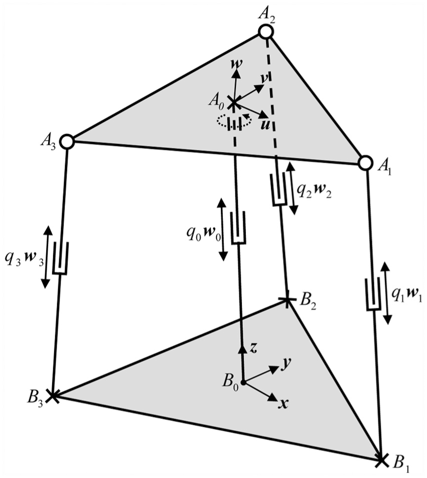
The 3UPS-PRU parallel robot is shown in Figure 1. This parallel robot is composed of a moving platform connected with the base platform through three identical UPS limbs and one PRU limb. The central PRU limb is fixed on the base platform. Here, the U, P, S, and R represent, respectively, a universal, prismatic, spherical, and revolute joint and underlined P (i.e. P) denotes an active prismatic joint driven by a servomotor. Due to the proper constraints of the central limb and the three external limbs, the moving platform has one translational and three rotational DOFs. The 3UPS-PRU parallel robot can be adopted to develop a motion simulator, rehabilitation appliance or used for other applications required for one translational and three rotational DOFs. The studied 3UPS-PRU parallel mechanism is used to build a hyper-redundant robot.
The 3 UPS-PRU parallel robot.
As shown in Figure 1, the following coordinate systems are defined for the modeling of the rigid-body dynamics: the reference coordinate system is located at the center of the base platform, and the moving coordinate system is attached to the center of mass of the moving platform. The orientation of the moving platform can be described by a rotation matrix . The rotation matrix can be defined by the parameters of roll, pitch, and yaw angle, namely, a rotation of about the fixed x-axis, a rotation about the fixed y-axis, and a rotation about the fixed z-axis. Thus, the rotation matrix is
The angular velocity and acceleration of the moving platform are given by12
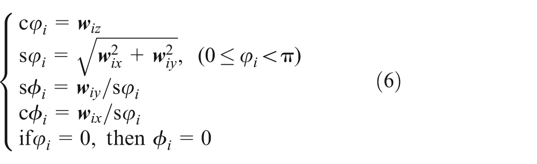
For the purpose of the rigid-body dynamic formulation, the local coordinate system of the ith limb is defined and shown in Figure 2. The orientation of the ith limb with respect to the base platform can be described by two angles. It can be thought of as a rotation of about z-axis resulting in a coordinate system followed by another rotation of about the rotated . So the rotation matrix can be written as
The local coordinate system of the ith limb.
The unit vector along the limb in the coordinate system is as follows
So the angles and can be computed as follows
Inverse kinematics
Position analysis
As shown in Figure 3, the position equation associated with the ith limb can be written as
where , , , , , and denote the joint variable of the central limb, the joint variable of the ith limb, the unit vector along the central limb, the unit vector along the ith limb, the vector , and the vector , respectively. also represents the position vector of the moving platform.
Vector diagram of the ith limb.
Taking norms on both sides of equation (7) leads to
Velocity analysis
Taking the derivative of equation (7) with respect to time, we get
where is the angular velocity vector of the ith limb and is the angular velocity vector of the moving platform.
Taking the dot product of both sides of equation (9) with , we obtain
By rewriting equation (10) in the matrix form, we obtain
where
where v is the linear velocity of the moving platform, is the velocity vector of the moving platform, and is the Jacobian matrix which maps the velocity vector of the moving platform into the joint velocity vector. There is a linear relationship between the velocity vector of the moving platform and the joint velocity vector.
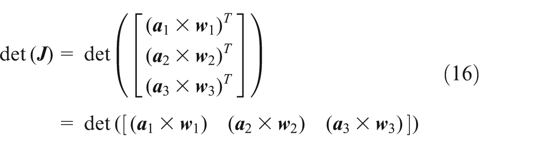
The determinant of Jacobian matrix can be obtained from equation (15)
Based on the theorem of vector operation, the determinant of Jacobian matrix can be achieved as
is the mixed product of vectors. The mixed product of vectors equals to zero when the three free vectors are in the same plane. So the determinant of Jacobian matrix equals to zero when any of the following conditions is satisfied.
It should be pointed out that the Jacobian matrix is a singular matrix in mathematics when the moving platform is parallel to the base platform and since the three vectors , , and are in the same plane.
Link velocity analysis
Taking the derivative of left side of equation (7) with respect to time, we get the velocity of the point of the joint
where is the linear velocity vector of the moving platform, and
Equation (21) can be described in the coordinate system
where .
Taking the derivative of right side of equation (7) with respect to time and describing the result in the coordinate system , we get the velocity of point of joint
where is the angular velocity of the ith limb described in the coordinate system .
Taking the cross product of both sides of equation (24) with and substituting into it, we obtain
denotes the link Jacobian matrix of the ith limb which maps the velocity vector of the moving platform in the task space into the angular velocity vector of the ith limb described in the coordinate system .
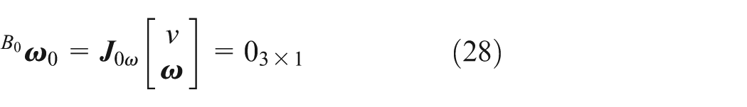
Since the central limb is fixed on the base platform, we can get
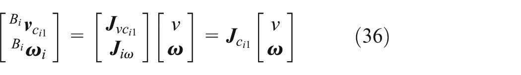
The linear velocity of the center of mass in the ith limb described in the coordinate system is
is the link Jacobian matrix which maps the velocity vector of the moving platform into the linear velocity vector of the center of mass .
For the central limb, we can get
Acceleration analysis
Taking the derivative of equation (9) with respect to time, we get
Taking the dot product of both sides of equation (43) with , we obtain
By rewriting equation (44) in the matrix form, we get
where is the acceleration of the moving platform along the central limb, and
From equation (26) and from equations (45) to (48), the joint acceleration related to the velocity of the moving platform is proportional to the square of the magnitude of the velocity of the moving platform.
Link acceleration analysis
Taking the derivative of equation (24) with respect to time and describing the result in the coordinate system , we get the acceleration of the point of the joint
Taking the cross product of both sides of equation (49) with and substituting into it, we obtain
where is the angular velocity vector of the moving platform.
For the central limb, we can get
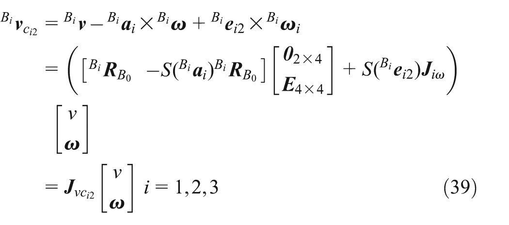
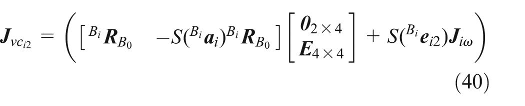
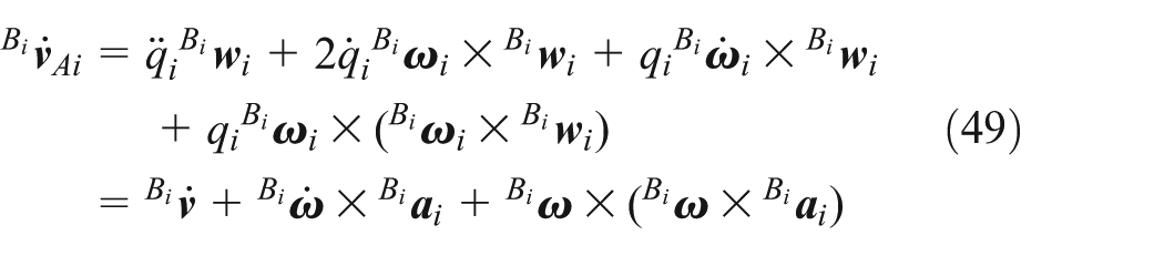
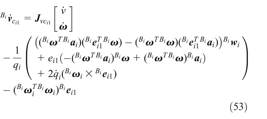
Taking the derivative of equation (30) with respect to time and describing the result in the coordinate system , we get the linear acceleration of the center of mass in the ith limb
Taking the derivative of equation (37) with respect to time and describing the result in the coordinate system , we get the linear acceleration of the center of mass in the ith limb
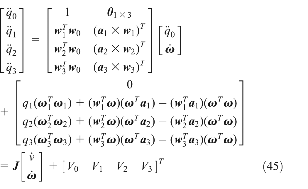
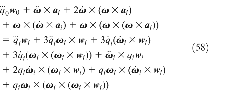
Taking the derivative of equation (43) with respect to time, we obtain
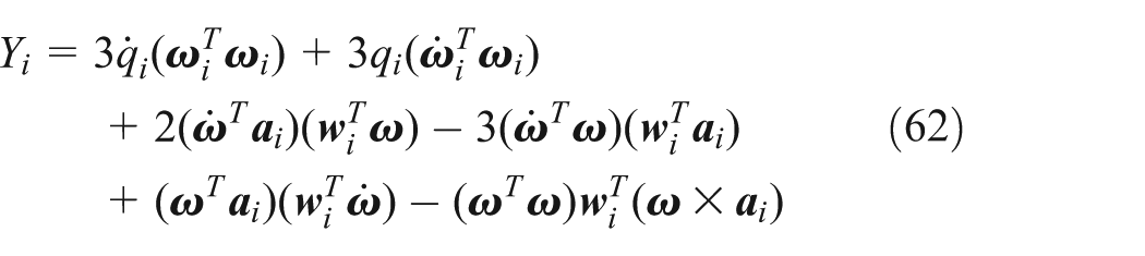
Taking the dot product of both sides of equation (58) with , we get
By rewriting equation (59) in the matrix form, we obtain
where and denote the linear jerk scalar along the central limb and the angular jerk vector of the moving platform, and
From equations (11), (26), (50), and (60)–(62), the joint jerk related to the velocity of the moving platform is proportional to the cubic of the magnitude of the velocity of the moving platform.
Inverse rigid-body dynamics
Applied and inertia moments
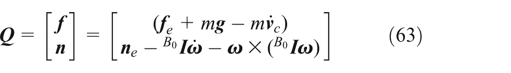
The resultant of applied and inertia forces exerted at the center of mass of the moving platform can be described in the coordinate system by
where m, , , and denote the mass of the moving platform, the acceleration of gravity, the external force, and moment exerted at the center of mass of the moving platform, respectively. is the inertia matrix of the moving platform about the center of mass in the coordinate system , and is the acceleration of the center of mass of the moving platform. When the rotation point is not the center of mass of the moving platform, we get
where is the vector from the point of joint to the center of mass of the moving platform, we can obtain
when the point of joint and the center of mass of the moving platform are the same point, we can get and .
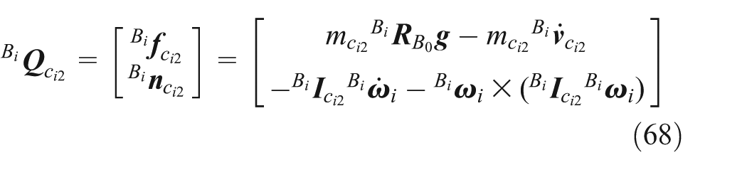
For the ith strut which is connected with the base platform, the resultant of applied and inertia forces exerted at the center of mass can be described in the coordinate system
where is the mass of the ith strut connected with the base platform and is the inertia matrix of the ith strut about the center of mass in the coordinate system .
Similarly, for the ith strut which is connected with the moving platform, the resultant of applied and inertia forces exerted at the center of mass can be described in the coordinate system
where is the mass of the ith strut connected with the moving platform and is the inertia matrix of the ith strut about the center of mass in the coordinate system .
Due to the rotation motion for lead screw, coupler, and motor, the resultant of applied and inertia forces exerted at the screw–coupler–rotor can be obtained
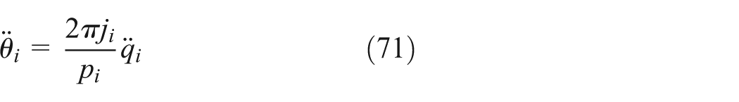
where is the input torque actuated by the motor; is the total rotary inertia of the lead screw, coupler, and motor rotor; is the angular acceleration of the motor rotor; and
where is the lead of the linear ball screw and is the reduction ratio.
Driving torque
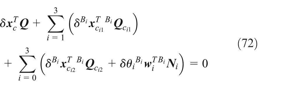
Extending the principle of the virtual work from the static to the dynamic case with the D’Alembert’s principle, we can get
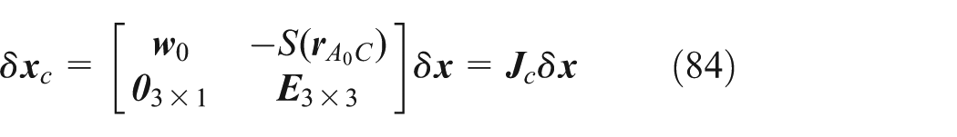
From equations (11), (36), (39), and (65), the relationships between the virtual displacement , , , , and the virtual displacement can be obtained
where is the rotational virtual displacement and the virtual displacement consists of the translational virtual displacement of the center of mass of the moving platform; is the rotational virtual displacement of the moving platform and the virtual displacement of the point of joint .
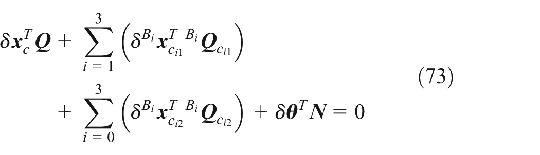
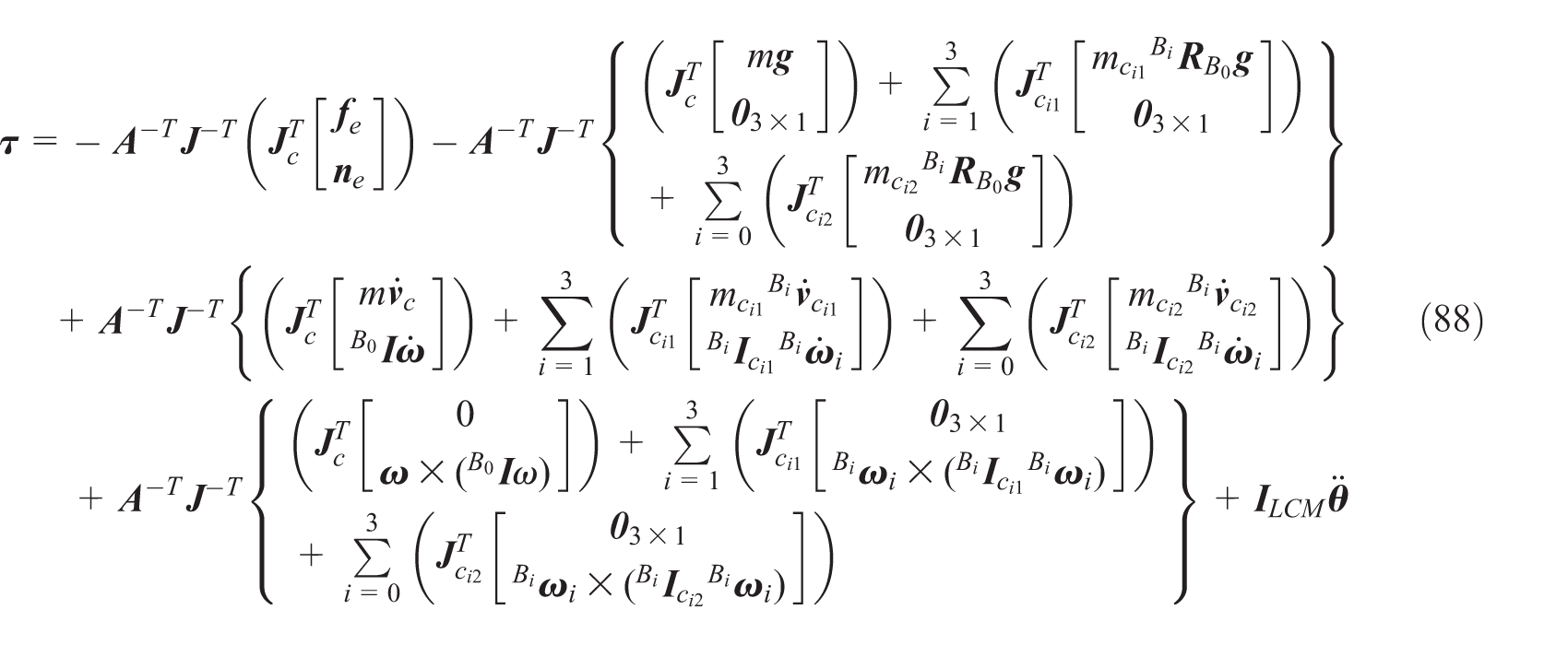
where , , , and are the torques related to the moving platform, strut connect with the moving platform, strut connected with the base platform, and motor rotor-coupler, respectively. , , , and are the torques related to the acceleration, velocity, gravity, and external force components, respectively. is the generalized inertia matrix which maps the acceleration of the moving platform into the driving torque
From equation (26), (50), (53), (55), and (88), the driving torque related to the velocity of the moving platform is proportional to the square of the magnitude of the velocity of the moving platform.
Driving power
The instantaneous required driving power of the ith actuating joint can be calculated by
where and are the driving torque and angular velocity of ith actuating joint, respectively.
where , , , and are the respective power components related to the moving platform, strut connected with the moving platform, strut connected with the base platform, and motor rotor-coupler. , , , and are the respective required powers of the ith actuating joint related to the acceleration component of torque, velocity component of torque, gravity component of torque, and external force component of torque, respectively.
From equations (26), (50), (53), (55), (88), and (91), the driving power related to the velocity of the moving platform is proportional to the cubic of the magnitude of the velocity of the moving platform. From equations (45), (50), (53), (55), (60), (88), and (91), there are linear relationships between the acceleration of the moving platform and the components of the joint acceleration, joint jerk, driving torque, and driving power, which are related to the acceleration of the moving platform.
Energy consumption
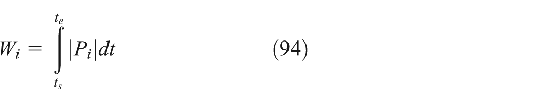
From the work-energy theorem and the concept of integral, the required output work generated by the ith driving motor during a specific motion period can be calculated by
where is the start time and is the end time of the motion.
Equation (94) can be implemented by the following numerical integration
where
And num is the number of the intervals, in general
where n is a positive integer. The error of the numerical computation should satisfy
where e is the maximum allowable numerical computation error and is the positive integer selected for the numerical integration.
Example
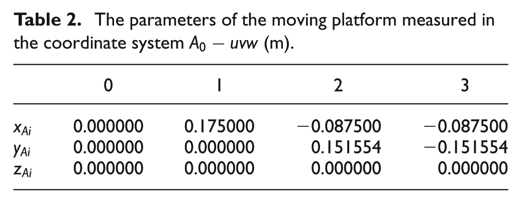
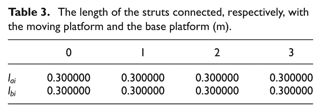
The numerical example for the computation of the position, velocity, acceleration, jerk, torque, power, and energy consumption for the 3UPS-PRU parallel robot is provided in this section when the trajectory of the moving platform is assigned. The parameters of the 3UPS-PRU parallel robot are given in Tables 1–4. The distance from the point of joint to the center of mass of the moving platform is . The trajectory of the moving platform is assigned as
where , , , , , .
The parameters of the base platform (m).
0
1
2
3
0.000000
0.200000
−0.100000
−0.100000
0.000000
0.000000
0.173205
−0.173205
0.000000
0.000000
0.000000
0.000000
The parameters of the moving platform measured in the coordinate system (m).
0
1
2
3
0.000000
0.175000
−0.087500
−0.087500
0.000000
0.000000
0.151554
−0.151554
0.000000
0.000000
0.000000
0.000000
The length of the struts connected, respectively, with the moving platform and the base platform (m).
0
1
2
3
0.300000
0.300000
0.300000
0.300000
0.300000
0.300000
0.300000
0.300000
The mass of the moving platform and the struts connected, respectively, with the moving platform and the base platform (kg).
2.597704
0.145047
0.099243
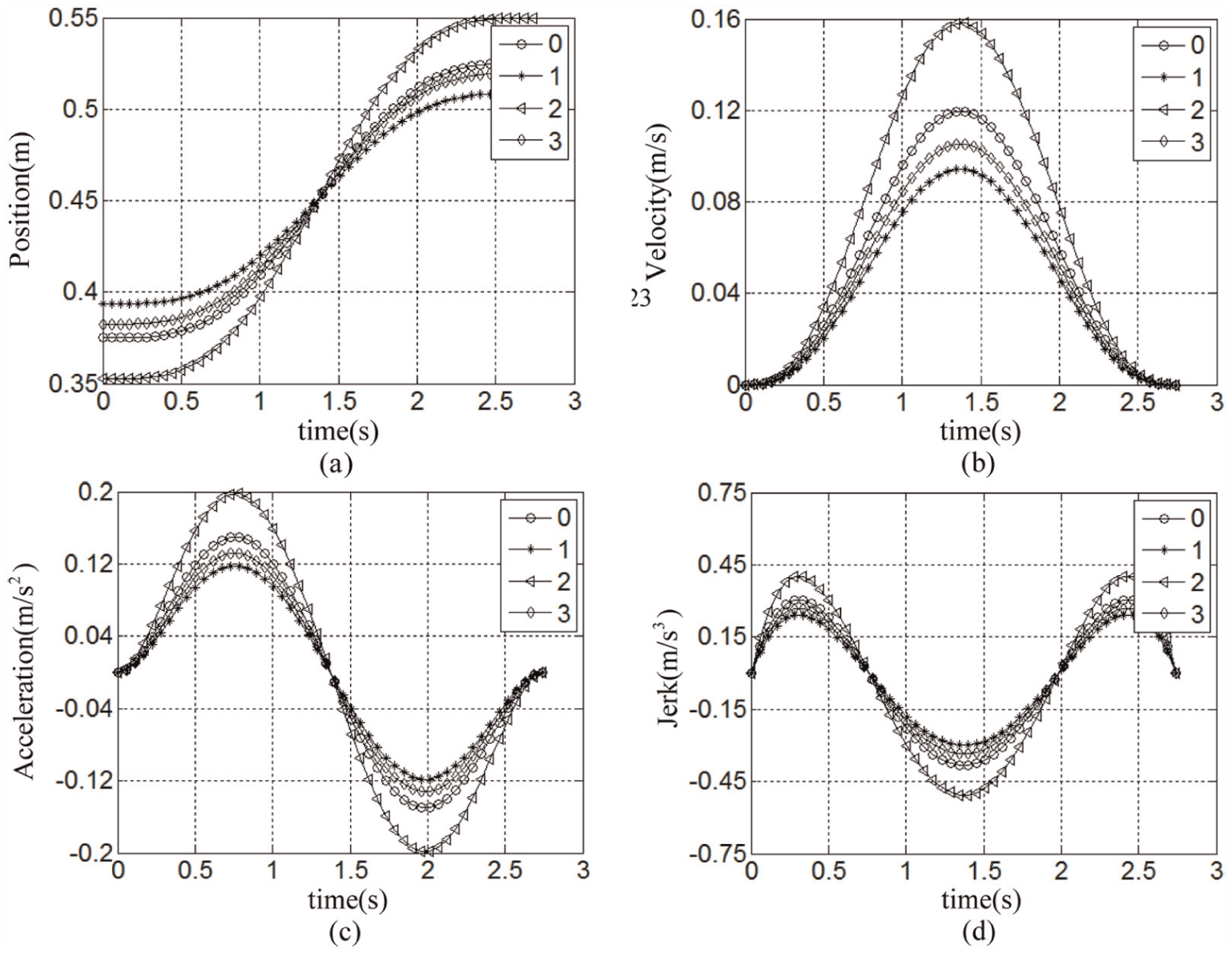
The variations of the position, velocity, acceleration, and jerk of the actuating joints are shown in Figure 4. It is shown in Figure 4 that the position, velocity, acceleration, and jerk of the second actuating joint are larger than those of the other three actuating joints. The velocity, acceleration, and jerk of the actuating joints are zeros at the start time and the end time of the specific motion period.
Variations of (a) position, (b) velocity, (c) acceleration, and (d) jerk of actuating joints versus time.
The total driving torques and the driving torques related to the acceleration, velocity, and gravity are shown in Figure 5. The effects of the external force on the driving torques are not considered since the relationship between the driving torque and the external force is simple. It is shown in Figure 5 that the total driving torque and the driving torques related to the acceleration, velocity, and gravity of the central limb are larger than those of the other three limbs due to the gravity of the moving platform. For the three outer limbs, the torque related to the acceleration is larger than the torques related to the velocity and gravity.
Variations of (a) total driving torques, (b) torques related to acceleration, (c) torques related to velocity, and (d) torques related to gravity versus time.
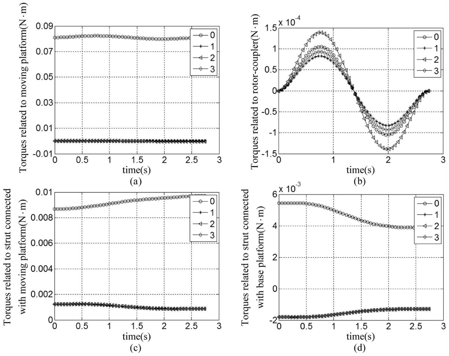
The driving torques related to the moving platform, motor rotor-coupler, strut connected with the moving platform, and strut connected with the base platform are shown in Figure 6. It is shown in Figure 6 that the driving torques related to the moving platform, strut connected with the moving platform, and strut connected with the base platform of the central limb are larger than those of the three outer limbs. The torque related to the moving platform is largest for the central limb. The torques related to the strut connected with the moving platform are larger than the torques related to the strut connected with the base platform.
Variations of driving (a) torques related to moving platform, (b) torques related to motor rotor-coupler, (c) torques related strut connected with the moving platform, and (d) torques related to strut connected with the base platform versus time.
The required driving powers of the actuating joint and the driving powers related to the acceleration component of torque, velocity component of torque, and gravity component of torque are shown in Figure 7. It is shown in Figure 7 that the driving power of the central limb is larger than those of the three outer limbs. For the central limb, the driving power is dominated by the component related to the gravity component of torque in the simulation.
Variations of (a) total driving powers, (b) powers related to acceleration component of torque, (c) powers related to velocity component of torque, and (d) powers related to gravity component of torque versus time.
The driving powers related to the moving platform, motor rotor-coupler, strut connected with the moving platform, and strut connected with the base platform are shown in Figure 8. It is shown in Figure 8 that the driving powers related to the moving platform, motor rotor-coupler, strut connected with the moving platform, and strut connected with the base platform of the central limb are larger than those of the three outer limbs. The power related to the moving platform is largest for the central limb. The powers related to the strut connected with the moving platform are larger than the powers related to the strut connected with the base platform. For the three outer limbs, the powers related to the strut connected with the moving platform are the largest, the powers related to the strut connected with the base platform take the second place, and the powers related to the moving platform and motor rotor-coupler are the smallest.
Variations of driving (a) powers related to moving platform, (b) powers related to motor rotor-coupler, (c) powers related strut connected with the moving platform, and (d) powers related to strut connected with the base platform versus time.
From the numerical technique, when the moving platform translates and rotates along the pre-defined trajectory presented in equation (99), the required output work generated by the ith driving motor can be achieved by equation (95). The positive integer and the approximation error are selected for the numerical integration computation. For the pre-defined trajectory, the required output work generated by the ith driving motor and the sum considering all four motors are shown in Table 5. It is shown in Table 5 that the required output work generated by the central motor is largest. The required output work generated by the three outer motors is small due to the support by the central limb and the self-balance of the moving platform.
The required output work generated by the ith driving motor and the sum considering four motors for the pre-defined trajectory (J).
0
1
2
3
Sum
4.471097
0.018114
0.030194
0.020261
4.539666
Conclusion
This article presents the inverse kinematics and rigid-body dynamics for a 3UPS-PRU parallel robot. The kinematics and rigid-body dynamics have been formulated and investigated in an exhaustive decoupled way. In the inverse kinematics analysis, the position, velocity, acceleration, jerk, and singularity have been considered. The driving torque, driving power, and required output work of motors have been computed in the inverse rigid-body dynamics analysis. The required output work generated by the driving motor is achieved by numerical integration technique. For the pre-defined trajectory, the required output work generated by the driving motor is achieved by numerical integration technique. The inverse kinematics and rigid-body dynamics have been investigated in an exhaustive decoupled way. There is a linear relationship between the velocity vector of the moving platform and the joint velocity vector. The components of the joint acceleration and driving torque, which are related to the velocity of the moving platform, are proportional to the square of the magnitude of the velocity of the moving platform. The components of the joint jerk and driving power, which are related to the velocity of the moving platform, are proportional to the cubic of the magnitude of the velocity of the moving platform. There are linear relationships between the acceleration of the moving platform and the components of the joint acceleration, joint jerk, driving torque, and driving power, which are related to the acceleration of the moving platform.
Footnotes
Acknowledgements
The authors would also like to thank the anonymous reviewers for their very useful comments.
Academic Editor: José Tenreiro Machado
Declaration of conflicting interests
The author(s) declared no potential conflicts of interest with respect to the research, authorship, and/or publication of this article.
Funding
The author(s) disclosed receipt of the following financial support for the research, authorship, and/or publication of this article: This research is jointly sponsored by the National Natural Science Foundation of China (Grant No. 51375288), the Science and Technology Program of Guangdong Province (Grant No. 2015B090906001), and the Special Research Foundation of Discipline Construction of Guangdong Province (Grant No. 2013KJCX0075).
References
1.
DongWDuZXiaoY. Development of a parallel kinematic motion simulator platform. Mechatronics2013; 23: 154–161.
2.
ZhaoYGaoFLiW. Development of 6-dof parallel seismic simulator with novel redundant actuation. Mechatronics2009; 19: 422–427.
3.
ChengGLiYFengL. Configuration bifurcation and self-motion analysis of 3SPS + 1PS bionic parallel test platform for hip joint simulator. Mech Mach Theory2015; 86: 62–72.
4.
StaicuS.Recursive modelling in dynamics of delta parallel robot. Robotica2009; 27: 199–207.
5.
LiHHYangZYHuangT.Dynamics and elasto-dynamics optimization of a 2-DOF planar parallel pick-and-place robot with flexible links. Struct Multidiscip O2009; 38: 195–204.
6.
ZhaoY.Dynamic performance evaluation of a three translational degrees of freedom parallel robot. Int J Robot Autom2012; 27: 31–40.
7.
LeAYMillsJKBenhabibB.Dynamic modeling and control design for a parallel-mechanism-based meso-milling machine tool. Robotica2014; 32: 515–532.
8.
ZhangD.Parallel robotic machine tools. New York: Springer, 2010.
9.
LiYWangJLiuXJ. Dynamic performance comparison and counterweight optimization of two 3-DOF parallel manipulators for a new hybrid machine tool. Mech Mach Theory2010; 45: 1668–1680.
10.
ZhaoY.Dynamic optimum design of a three translational degrees of freedom parallel robot while considering anisotropic property. Robot Cim: Int Manuf2013; 29: 100–112.
11.
ChenCTLiaoTT.A hybrid strategy for the time- and energy-efficient trajectory planning of parallel platform manipulators. Robot Cim: Int Manuf2011; 27: 72–81.
12.
TsaiLW.Solving the inverse dynamics of a Stewart-Gough manipulator by the principle of virtual work. J Mech Des: T ASME2000; 122: 3–9.
13.
HuangTMeiJPLiZX.A method for estimating servomotor parameters of a parallel robot for rapid pick-and-place operations. J Mech Des: T ASME2005; 127: 596–601.
14.
ZhaoYQiuKWangS. Inverse kinematics and rigid-body dynamics for a three rotational degrees of freedom parallel manipulator. Robot Cim: Int Manuf2015; 31: 40–50.
15.
ZhaoYGaoF.The joint velocity, torque and power capability evaluation of a redundant parallel manipulator. Robotica2011; 29: 483–493.
16.
CodoureyA.Dynamic modeling of parallel robots for computed-torque control implementation. Int J Robot Res1998; 17: 1325–1336.
17.
ZhangDBiZMLiBZ.Design and kinetostatic analysis of a new parallel manipulator. Robot Cim: Int Manuf2008; 25: 782–791.
18.
AbdellatifHHeimannB.Computational efficient inverse dynamics of 6-DOF fully parallel manipulators by using the Lagrangian formalism. Mech Mach Theory2009; 44: 192–207.
19.
LiuMJLiCXLiCN.Dynamics analysis of the Gough–Stewart platform manipulator. IEEE T Robotic Autom2000; 16: 94–98.
20.
ZhaoYGaoF.Inverse dynamics of the 6-dof out-parallel manipulator by means of the principle of virtual work. Robotica2009; 27: 259–268.
21.
Ur-RehmanRCaroSChablatD. Multi-objective path placement optimization of parallel kinematics machines based on energy consumption, shaking forces and maximum actuator torques: application to the Orthoglide. Mech Mach Theory2010; 45: 1125–1141.
22.
StaicuSZhangD.A novel dynamic modelling approach for parallel mechanisms analysis. Robot Cim: Int Manuf2008; 24: 167–172.
23.
LiYMXuQS. Dynamic analysis of a modified DELTA parallel robot for cardiopulmonary resuscitation. In: Proceedings of the IEEE/RSJ international conference on intelligent robotics and systems, Edmonton, AB, Canada, 2–6 August 2005, pp.3371–3376. New York: IEEE.
24.
WuJWangJSWangLP. Dynamics and control of a planar 3-DOF parallel manipulator with actuation redundancy. Mech Mach Theory2009; 44: 835–849.
25.
GallardoJRicoJMFrisoliA. Dynamics of parallel manipulators by means of screw theory. Mech Mach Theory2003; 38: 1113–1131.
26.
StaicuSLiuXJLiJ.Explicit dynamics equations of the constrained robotic systems. Nonlinear Dyn2009; 58: 217–235.
27.
StaicuS.Dynamics of the spherical 3-UPS/S parallel mechanism with prismatic actuators. Multibody Syst Dyn2009; 22: 115–132.