This article deals with the methodology of the dynamic optimum design of the one translational and three rotational degrees of freedom parallel robots while considering the rigid-body dynamic property. The dynamic optimum design of the 3UPS-PRU (underlined P denotes an active prismatic joint driven by a servomotor) parallel robot is presented while considering the constraints on the installation dimension, joint rotation angle, and the interference. The maximum driving torque and the maximum driving power of the actuating joints are taken as the objective functions in the dynamic optimum design, respectively. The physical meanings of the objective functions are the maximum driving torque and the maximum driving power of the actuating joints when the moving platform translates along the z-axis in the maximum linear acceleration amax, rotates about an arbitrary axis in the maximum angular acceleration αmax, translates along the z-axis in the maximum linear velocity vmax, and rotates about an arbitrary axis in the maximum angular velocity ωmax at the same time. The object of the dynamic optimum design is to minimize the maximum driving torque or the maximum driving power by employing worst case criterion. In the predefined design task, the results of the dynamic optimum design of the 3UPS-PRU parallel robot are the same when taking the maximum driving torque and the maximum driving power as the objective functions. The phenomenon can be verified by the fact that the distributions of the maximum driving torque and the maximum driving power are very similar to each other. The robot dimension has also been taken into account in the dynamic optimum design of the 3UPS-PRU parallel robot due to the consideration of the building cost and the miniaturization. The example of the dynamic optimum design of the 3UPS-PRU parallel robot is presented in the simulation. The conclusions are provided at the end of the article.
Parallel robots have been successfully used in machine tools with high precision requirement,1–5 motion simulators with heavy load,6–8 pick-and-place operations with high speed or high acceleration,9–12 engineering machineries with good mobility performance,13 and so on. The dynamic characteristic should be taken into account in the design stage when the parallel robot is used for the applications with high precision requirement,3 high speed/or acceleration operation,10,14,15 heavy load situation,7 and so on.
Dynamic optimum design of the parallel robot is to determine the appropriate dimension and inertia of the mechanical structure in order to achieve an optimal dynamic performance. Dynamic optimum design is usually a nonlinear optimization problem. The design variables of the dynamic optimum design of the parallel robots are structural parameters such as link length14 and section dimension.10 The objective functions adopted in the dynamic optimum design are usually dynamic performance index such as balance,16–18 dynamic isotropy,19,20 torque index,14,21,22 power index,14 natural frequency,10,21,23 dynamic response,24 dynamic load-carrying capacity,25 and so on. Due to the consideration of the prototype building and cost, some constraints26–29 such as boundary constraint, dimension constraint, and transmission constraint14,22,27 should be taken into account in the dynamic optimum design of the parallel robot. It is shown that the constraints play a role in the dimensional synthesis considering kinematic property may take no effect on the results of the dynamic optimum design of the parallel robot.14 The dynamic optimum design of the parallel robot is usually solved by the numerical technique since the relationship between the objective function and the design variables cannot be described by an explicit expression. The numerical methods used in the dynamic optimum design of the parallel robots include sequential quadratic programming,14,21,22,26,27 Newton method and its modification,30 genetic algorithms,3,31 particle swarm optimization,32 and so on. Some of the aforementioned algorithms are available in MATLAB® optimization toolbox. It should be pointed out that the dynamic optimum design of a parallel robot is a multicriteria optimization problem. For a specific parallel robot, the dynamic optimum design should be carried out by applying the appropriate constraints while considering the application and the performance requirement.
The aim of this article is to present a work on the dynamic optimum design of a 3UPS-PRU parallel robot while considering the rigid-body dynamic property. The maximum driving torque and the maximum driving power of the actuating joints are taken as the objective functions, respectively. The constraints on the installation dimension, joint rotation angle, and interference are considered in the design. The article is organized as follows. The 3UPS-PRU parallel robot is explained in section “3UPS-PRU parallel robot.” The rigid-body dynamic model used in the dynamic optimum design is provided in section “Rigid-body dynamic model.” Dynamic optimum design of the 3UPS-PRU parallel robot is investigated in section “Dynamic optimum design.” Design example is illustrated in section “Design example,” and the final section gives the conclusions.
3UPS-PRU parallel robot
The 3UPS-PRU parallel robot is shown in Figure 1. The moving platform is connected with the base platform by three external identical limbs and one central limb. The external limb is composed of a universal, prismatic, and spherical joint. The central limb consists of a prismatic, revolute, and universal joint. The central limb is fixed on the base platform. All the limbs are driven by the prismatic joint. There are one translational and three rotational degrees of freedom for the moving platform due to the constraints of the three external limbs and the central limb.
The 3UPS-PRU parallel robot.
As shown in Figure 1, the orientation of the moving platform can be described by a rotation matrix
of the moving coordinate system with respect to the reference coordinate system . The moving coordinate system and the reference coordinate system are located at the center of mass of the moving platform and the center of the base platform, respectively. The rotation matrix can be described by the parameters of roll, pitch, and yaw angle, namely, a rotation of φx about the fixed x-axis, a rotation φy about the fixed y-axis, and a rotation φz about the fixed z-axis. So, the rotation matrix is
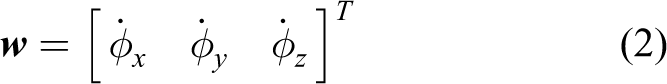
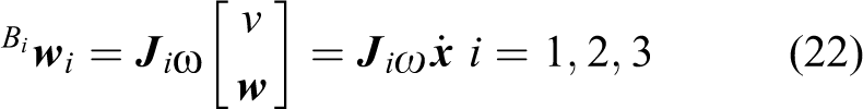
The angular velocity and acceleration of the moving platform can be described by33
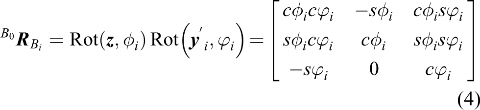
The ith limb and its local coordinate system are defined and shown in Figures 2 and 3 for the purpose of the rigid-body dynamic formulation. The orientation of the ith limb with respect to the base platform can be described by two angles. It can be thought of as a rotation of φi about z-axis resulting in a coordinate system followed by another rotation of ϕi about the rotated -axis. So, the rotation matrix can be written as
The local coordinate system of the ith limb.
Vector diagram of the ith limb.
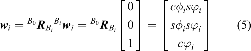
The unit vector along the limb described in the coordinate system is
So, the angles φi and ϕi can be obtained as
Rigid-body dynamic model
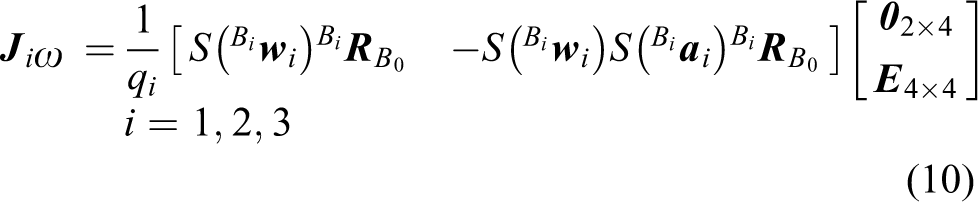
The rigid-body dynamic model of the 3UPS-PRU parallel robot can be developed by means of the principle of virtual work and the link Jacobian matrices. It can be expressed as
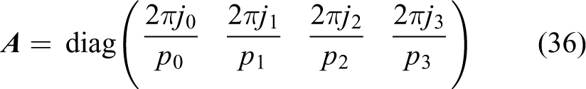
where τ is the driving torque vector of the actuating joint; fe and ne denote the external force and moment exerted at the center of mass of the moving platform; J is the Jacobian matrix that maps the velocity vector of the moving platform into the joint velocity vector; are the ith link Jacobian matrices that map the velocity vector of the moving platform in the task space into the velocity vectors of the respective sleeve connected with the base platform and the push rod connected with the moving platform described in the coordinate system ; m, denote the mass of the moving platform, the mass of the sleeve, and the mass of the push rod, respectively. is the inertia matrix of the moving platform about the center of mass in the coordinate system is the inertia matrix of the ith sleeve about the center of mass in the coordinate system is the inertia matrix of the ith push rod about the center of mass in the coordinate system are the angular velocity and acceleration of the moving platform; is the linear acceleration of the center of mass of the moving platform; are the angular velocity and acceleration of the ith limb; are the linear accelerations of the center of mass of the sleeve and the push rod; g is the acceleration of gravity; ILCM is the total rotary inertia of the lead screw, coupler, and motor rotor; is the angular acceleration of the motor rotor, and
where pi is the lead of the linear bass screw and ji is the reduction ratio.
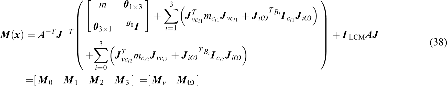
is the generalized inertia matrix that maps the acceleration of the moving platform into the driving torque. are the driving torques related to the acceleration, velocity, gravity, and external force components, respectively. For the 3UPS-PRU parallel robot, there is no external force exerted on the moving platform for the application, so
The instantaneous required driving power of the ith actuating joint is
where Pia,Piv, are the respective driving powers of the ith actuating joint related to the acceleration component of torque, velocity component of torque, gravity component of torque, and external force component of torque.
Dynamic optimum design
Dynamic optimum design of the 3UPS-PRU parallel robot is to determine the structural parameters in order to achieve an optimal dynamic performance for an assigned task. It is usually a nonlinear optimization problem.
Design task
The desired workspace Wd of the 3UPS-PRU parallel robot is assigned as
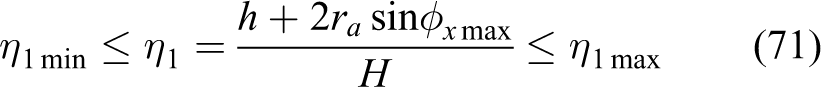
where H is the distance from the central point of the desired workspace to the central point of the base platform; h is the translational range along the z-axis; are the rotational ranges about the x-axis, y-axis, and z-axis, respectively.
The 3UPS-PRU parallel robot is assigned to fulfill operation in the desired workspace with the required maximum linear acceleration amax, maximum linear velocity vmax, maximum angular acceleration αmax, and maximum angular velocity ωmax at the same time. The object of the dynamic optimum design is to achieve an optimal performance from the perspective of the rigid-body dynamics.
Design variable
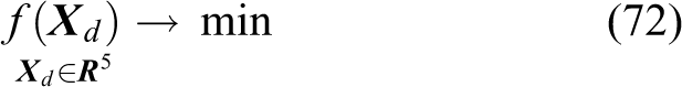
The structure of the 3UPS-PRU parallel robot can be described by the following parameters: ra is the radius of the moving platform, rb is the radius of the base platform, la is the length of the push rod, and lb is the length of the sleeve. should be big enough to mount the joints and the servomotors. The object of the dynamic optimum design is to achieve an optimal rigid-body dynamic performance in the desired workspace while not in the whole reachable workspace. A design variable should be assigned to describe the relationship between the desired workspace and the whole reachable workspace. Here, the distance between the central point of the desired workspace and the central point of the base platform is adopted to denote the relationship. place restriction on the maximum length and the minimum length of the telescopic rod. So, the design variable for the dynamic optimum design of the 3UPS-PRU parallel robot is
Objective function
When the moving platform translates along or rotates about the axes in the unit acceleration, the driving torques related to the acceleration can be obtained from equation (37)
where
From equation (37), the driving torques related to the velocity can be obtained as
The driving torques related to the gravity can be obtained from equation (37)
From equations (45) to (51), when the moving platform translates along the z-axis in the maximum linear acceleration amax, rotates about an arbitrary axis in the maximum angular acceleration αmax, translates along the z-axis in the maximum linear velocity vmax, and rotates about an arbitrary axis in the maximum angular velocity ωmax, the driving torque and the driving power should be satisfied
The object of the dynamic optimum design is to achieve an optimal rigid-body dynamic performance. By taking the maximum driving torque and the maximum driving power of the actuating joints as the objective functions, the dynamic optimum design is carried out, respectively. So, the objective functions are
The physical meanings of the objective functions are the maximum driving torque and the maximum driving power of the actuating joints when the moving platform translates along the z-axis in the maximum linear acceleration amax, rotates about an arbitrary axis in the maximum angular acceleration αmax, translates along the z-axis in the maximum linear velocity vmax, and rotates about an arbitrary axis in the maximum angular velocity ωmax at the same time. It should be pointed out that the worst case criterion is employed in the dynamic optimum design in this article to optimize the rigid-body dynamic performance of the 3UPS-PRU parallel robot since the maximum driving torque and the maximum driving power only probably occur in the worst case.
Constraints
A set of appropriate constraints regarding the assembly condition and prototype building should be considered in the dynamic optimum design of the 3UPS-PRU parallel robot. The moving platform and the base platform should be big enough to mount the joints and the servomotors. In general, the base platform is bigger than the moving platform since the installation dimension of the servomotors is bigger than that of the joints. The studied 3UPS-PRU parallel mechanism is used to build a hyper redundant robot. The constraint on the maximum value of the base platform should also be considered. So, the constraints on the dimensions of the base platform and the moving platform can be described as
The constraint on the ratio of the stroke of the UPS limb and the PRU limb to the minimum lengths should be considered.28,29 This is because the span between two support bearings of the limb should be large enough to provide sufficient stiffness. The constraint can be described as
where μ0 is the maximum allowable value of μ. A value of 0.6–0.8 is recommended while considering the miniaturization of the 3UPS-PRU parallel robot and the specification of the commercial telescopic rod. For the dynamic optimum design of the 3UPS-PRU parallel robot, is adopted. In order to ensure the installation, the minimum length of the telescopic rod should be bigger than the minimum installation dimension. So, the constraint is
where smin is the minimum installation dimension. Considering the computation and the specification of the commercial telescopic rod, is adopted in the dynamic optimum design of the 3UPS-PRU parallel robot.
Considering the structure of the telescopic rod and the installation dimension, the constraints should be set by
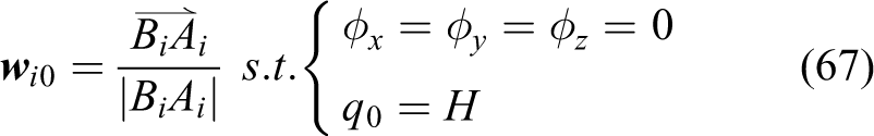
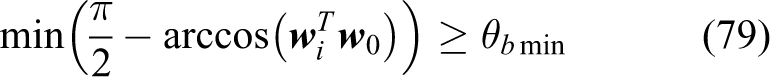
The limit on the rotation angle of the spherical joint should be considered as
where θs max is the maximum allowable rotation angle of the spherical joint, wi0 is the unit vector of the ith limb on the initial configuration
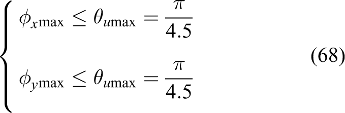
The constraint on the rotation angle of the universal joint should be set by
where θu max is the maximum allowable rotation angle of the universal joint.
In order to avoid the interference between the limb and the base platform/or the moving platform, the constraints should be set by
Considering the miniaturization and the building cost, the robot dimension should be taken into account in the dynamic optimum design of the 3UPS-PRU parallel robot. The corresponding constraint should be set by
In light of the dynamic optimum design of the 3UPS-PRU parallel robot, would be reasonable choices.
Optimization implementation
The dynamic optimum design of the 3UPS-PRU parallel robot can be formulated as the following nonlinear constrained optimization problem subject to equations (56) to (66) and equations (68) to (71)
The nonlinear constrained optimization problem can be solved by the sequential quadratic programming algorithm available in MATLAB optimization toolbox. The objective function and the constraints can be calculated on the condition that
where z,θx,θy, and θz are the pose of the moving platform and Wd is the desired workspace that is meshed with nodes. The objective function and the constraints can be calculated, respectively, when the moving platform is on each node of the meshed workspace, then the maximum objective function and the minimum constraint/or the maximum constraint can be searched out in the exhaustive way.
Design example
In this section, the dynamic optimum design of the 3UPS-PRU parallel robot is presented when the design task is assigned. The rotational ranges of the moving platform about the x-axis, y-axis, and z-axis are assigned as , respectively. The translational range along the z-axis is . In the desired workspace, the moving platform translates along the z-axis in the maximum linear acceleration , rotates about an arbitrary axis in the maximum angular acceleration , translates along the z-axis in the maximum linear velocity , and rotates about an arbitrary axis in the maximum angular velocity at the same time.
The results of the dynamic optimum design of the 3UPS-PRU parallel robot subject to are presented in Table 1. It is shown that the results of the dynamic optimum design of the 3UPS-PRU parallel robot are the same when taking the maximum driving torque and the maximum driving power as the objective functions.
Dynamic optimum design of the 3UPS-PRU parallel robot subject to
The results of the dynamic optimum design of the 3UPS-PRU parallel robot subject to different constraints η1 min are presented in Table 2. It is shown that the constraint of equation (71) takes no effect on the result of the dynamic optimum design when . The result of the dynamic optimum design shows that H will be big when η1 min becomes big. It is different from the results of the dimensional synthesis of the 3UPS-PRU parallel robot considering kinematic property. η1 min should not be too big otherwise the constraint on the dimension of rb max should be cancelled. would be a reasonable choice from the computation and analysis. In this article, is adopted in the dynamic optimum design of the 3UPS-PRU parallel robot.
Dynamic optimum design of the 3UPS-PRU parallel robot subject to different constraints of η1 min
From Table 1, when the moving platform translates along the z-axis in the maximum linear acceleration , rotates about an arbitrary axis in the maximum angular acceleration , translates along the z-axis in the maximum linear velocity , and rotates about an arbitrary axis in the maximum angular velocity , the results of the dynamic optimum design of the 3UPS-PRU parallel robot subject to are
The parameters are rounded as
The distributions of the maximum driving torque, the maximum driving power, and the constraints are shown in Figure 4 when the moving platform translates along the z-axis in the maximum linear acceleration , rotates about an arbitrary axis in the maximum angular acceleration , translates along the z-axis in the maximum linear velocity , and rotates about an arbitrary axis in the maximum angular velocity , where , and the upper layer, the middle layer, and the bottom layer correspond to , respectively. It is shown that the distributions of the maximum driving torque and the maximum driving power are very similar to each other. This verifies that the results of the dynamic optimum design of the 3UPS-PRU parallel robot are the same when taking the maximum driving torque and the maximum driving power as the objective functions.
Distributions of (a) maximum driving torque, (b) maximum driving power, (c) , (d) , and (e) when the moving platform on the plane associated with the upper, middle and bottom layers of the desired workspace.
Conclusions
The dynamic optimum design of the 3UPS-PRU parallel robot is presented while considering the constraints on the installation dimension, joint rotation angle, and the interference. The following conclusions are drawn:
When the moving platform translates along the z-axis in the maximum linear acceleration amax, rotates about an arbitrary axis in the maximum angular acceleration αmax, translates along the z-axis in the maximum linear velocity vmax, and rotates about an arbitrary axis in the maximum angular velocity ωmax, the maximum driving torque and the maximum driving power the actuating joints are achieved based on the rigid-body dynamics, theory of matrix norm, and inequality. The maximum driving torque and the maximum driving power of the actuating joints are taken as the objective functions in the dynamic optimum design of the 3UPS-PRU parallel robot, respectively. The object of the dynamic optimum design is to minimize the maximum driving torque or the maximum driving power by employing worst case criterion.
In the presented design task, the results of the dynamic optimum design of the 3UPS-PRU parallel robot are the same when taking the maximum driving torque and the maximum driving power as the objective functions. The phenomenon can be verified by the fact that the distributions of the maximum driving torque and the maximum driving power are very similar to each other.
The constraints on the joint rotation range, installation dimension, and interference are considered in the dynamic optimum design. The robot dimension has also been taken into account in the dynamic optimum design of the 3UPS-PRU parallel robot due to the considering of the building cost and the miniaturization. The robot dimension is an important factor and should be determined by the building cost, overall dimension, and desired performance of the 3UPS-PRU parallel robot.
The proposed methodology could be useful for the dynamic optimum design of other parallel robots with one translational and three rotational degrees of freedom.
Footnotes
Acknowledgements
The authors would like to thank the anonymous reviewers for their very useful comments.
Declaration of conflicting interests
The author declared no potential conflicts of interest with respect to the research, authorship, and/or publication of this article.
Funding
The author(s) disclosed receipt of the following financial support for the research, authorship, and/or publication of this article: This research is jointly sponsored by the National Natural Science Foundation of China (grant no. 51375288), the Science and Technology Program of Guangdong Province (grant no. 2015B090906001), and the Special Research Foundation of Discipline Construction of Guangdong Province (grant no. 2013KJCX0075).
References
1.
CaccavaleFSicilianoBVillaniL. The Tricept robot: dynamics and impedance control. IEEE/ASME Trans Mechatronics2003; 8(2): 263–268.
2.
LiMHuangTMeiJP. Dynamic formulation and performance comparison of the 3-dof modules of two reconfigurable PKM—the Tricept and the TriVariant. ASME J Mech Design2005; 127(6): 1129–1136.
3.
ZhangDGosselinCM. Kinetostatic analysis and design optimization of the Tricept machine tool family. ASME J Manuf Sci Eng2002; 124(3): 725–733.
4.
JiangSSunFDLouJL. Kinematics, error analysis, and compensation of a high precision tendon-based mri-compatible robot. Int J Robot Autom2015; 30(4): 333–344.
5.
WuJWangJSWangLP. Dynamics and control of a planar 3-DOF parallel manipulator with actuation redundancy. Mech Mach Theory2009; 44(4): 825–849.
6.
DongWDuZJXiaoYQ. Development of a parallel kinematic motion simulator platform. Mechatronics2013; 23(1): 154–161.
7.
ZhaoYJGaoFLiWM. Development of 6-dof parallel seismic simulator with novel redundant actuation. Mechatronics2009; 19(3): 422–427.
8.
ChengGLiYFengLL. Configuration bifurcation and self-motion analysis of 3SPS + 1PS bionic parallel test platform for hip joint simulator. Mechanism and Machine Theory2015; 86: 62–72.
9.
StaicuS. Recursive modelling in dynamics of Delta parallel robot. Robotica2009; 27(2): 199–207.
10.
LiHHYangZYHuangT. Dynamics and elasto-dynamics optimization of a 2-dof planar parallel pick-and-place robot with flexible links. Struct Multidiscip O2009; 38(2): 195–204.
11.
ZhaoYJ. Dynamic performance evaluation of a three translational degrees of freedom parallel robot. Int J Robot Autom2012; 27(1): 31–40.
12.
DekkerRKhajepourABehzadipourS. Design and testing of an ultra high-speed cable robot. Int J Robot Autom2006; 21(1): 25–34.
13.
ZiBLinJQianS. Localization, obstacle avoidance planning and control of cooperative cable parallel robots for multiple mobile cranes. Robot Comput Integr Manuf2015; 34: 105–123.
14.
ZhaoYJ. Dynamic optimum design of a three translational degrees of freedom parallel robot while considering anisotropic property. Robot Comput Integr Manuf2013; 29(4): 100–112.
15.
ZiBCaoJZhuZ. Dynamic simulation of hybrid-driven planar five-bar parallel mechanism based on SimMechanics and tracking control. Int J Adv Robot Syst2011; 8(4): 28–33.
AliciGShirinzadehB. Optimum dynamic balancing of planar parallel manipulators based on sensitivity analysis. Mech Mach Theory2006; 41(12): 1520–1532.
18.
IliaDSinatraR. A novel formulation of the dynamic balancing of five-bar linkages with applications to link optimization. Multibody Syst Dyn2009; 21(2): 193–211.
19.
MaOAngelesJ. Optimum design of manipulators under dynamic isotropy conditions. In: Proceedings of the IEEE international conference on robotics and automation, Atlanta, USA, 2–6 May 1993, pp. 470–475. DOI: 10.1109/ROBOT.1993.292024
20.
TongZZHeJFJiangHZ. Optimal design of a class of generalized symmetric Gough–Stewart parallel manipulators with dynamic isotropy and singularity-free workspace. Robotica2012; 30(2): 305–314.
21.
ZhaoYJ.Dynamic design theory and methodology of the high-speed and light-weight parallel robot (in Chinese). PhD Dissertation, Tianjin University, China2006.
22.
ZhangLMMeiJPZhaoXM. Dimensional synthesis of the Delta robot using transmission angle constraints. Robotica2012; 30(3): 343–349.
23.
KozakKEbert-UphoffIVoglewedePA. Concept paper: on the significance of the lowest linearized natural frequency of a parallel manipulator as a performance measure for concurrent design. In: GosselinClement M.Ebert-UphoffImme (eds) Proceedings of the WORKSHOP on fundamental issues and future research directions for parallel mechanisms and manipulators, Quebec, Canada, 3–4 October 2002, pp. 112–118.
24.
da SilvaMMde OliveiraLPRBrülsO. Integrating structural and input design of a 2-dof high-speed parallel manipulator: a flexible model-based approach. Mech Mach Theory2010; 45(11): 1509–1519.
25.
ChenXLWuJWangLP. Optimum design of a parallel conveyor for electrocoating of vehicle bodies. Int J Robot Autom2016; 31(3): 198–205.
26.
HuangTLiZXLiM. Conceptual design and dimensional synthesis of a novel 2-dof translational parallel robot for pick-and-place operations. ASME J Mech Design2004; 126(3): 449–455.
27.
ZhaoYJ. Dimensional synthesis of a three translational degrees of freedom parallel robot while considering kinematic anisotropic property. Robot Compu Integr Manuf2013; 29(1): 169–179.
28.
HuangTLiMZhaoXM. Conceptual design and dimensional synthesis for a 3-dof module of the TriVariant—a novel 5-dof reconfigurable hybrid robot. IEEE Trans Robot2005; 21(3): 449–456.
29.
LiuHTHuangTZhaoXM. Optimal design of the TriVariant robot to achieve a nearly axial symmetry of kinematic performance. Mech Mach Theory2007; 42(12): 1643–1652.
30.
RaoNMRaoKM. Multi-position dimensional synthesis of a spatial 3-RPS parallel manipulator. ASME J Mech Design2006; 128(4): 815–819.
31.
ZiBDingHCaoJ. Integrated mechanism design and control for completely restrained hybrid-driven based cable parallel manipulators. J Intell Robot Syst2014; 74(3–4): 643–661.
32.
YunYLiYM. Optimal design of a 3-PUPU parallel robot with compliant hinges for micromanipulation in a cubic workspace. Robot Comput Int Manuf2011; 27(6): 977–985.
33.
TsaiLW. Solving the inverse dynamics of a Stewart-Gough manipulator by the principle of virtual work. ASME J Mech Design2000; 122(1): 3–9.