
Abstract
Prosthetic knee joint (PKJ) is an important apparatus for trans-femoral amputees to regain walking ability. This study has two objectives: (1) to design a high performance and low-cost passive PKJ and (2) to evaluate the performance of the PKJ. In the proposed PKJ design, a four-bar linkage was employed as the mechanical structure, and parallel spring and damper were used as the two connecting rods of the four-bar linkage. With the parallel spring, the length of the connecting rod is variable and a buffer flexion angle can be generated, which was consistent with that of the human knee joint. The damper was used to regulate the swing speed of the shank. Through theoretical analysis, modeling, and simulation, key parameters of the mechanical structure were optimized. Finally, experimental studies were conducted to test the performance of the PKJ, including fatigue test and gait analysis. The results showed that the designed PKJ is reliable and the gait of PKJ is close to the healthy subject. Moreover, it is comfortable and showed no adverse effects on the amputee during the walking experiment.
Keywords
Introduction
Walking is a fundamental daily activity for human beings. For lower limb amputees, the loss of the walking ability causes a lot of inconveniences in their daily life. Currently, the most effective way to regain walking ability is to use prostheses. In all prosthetics components for a trans-femoral amputee, prosthetic knee joint (PKJ) is a critical component that can affect the overall performance of walking. In past few decades, lots of work has been done to improve the PKJs. Generally, PKJs can be divided into passive PKJ and active PKJ according to the power requirement. There are many active prosthesis proposed in the literature, such as geared active prosthesis, 1 agonist–antagonist active knee prosthesis, 2 intelligent mechanical active PKJ with ball screw and servo motor, 3 pneumatically powered knee and ankle joints, 4 and a powered knee prosthesis for volitional movement during non-weight-bearing activities. 5 For all active PKJs, motors or actuators are the indispensable components. As a result, they must be equipped with rechargeable batteries, which increases the weight and volume and restricts the duration of operation due to the battery capacity. Consequently, power issue restricted the applications of active PKJs. For commercially available PKJs from Otto Bock®, Ossur®, and Endolite®, the majorities are passive PKJs, such as 3R55 from Otto Bock, 6 seven-axial knee 1900 from ossur, 7 and KX06 from Endolite. 8 Compared with active PKJs, the passive prostheses often have a higher reliability and do not rely on batteries.
There are several mechanisms that can realize the function of PKJs, which can be divided into single-axis knee joints and multi-axis knee joints. A single-axis prosthetic knee using magnetorhelogical fluid damper was designed in,
9
and the knee joint angle could be controlled by inducing the magnetic field during the stance phase. Another single-axis manual lock knee was designed in.
10
The manual lock knee is appropriate for weak or unstable patients as well as more active individuals who frequently walk on unstable terrain, and the single-axis mechanism makes the knee relative simplicity and more economical. A biomechatronic knee prosthesis was proposed in.
11
It is an intelligent PKJ based on single-axis mechanism. Although the single-axis joint is simple and small size, the instantaneous center of the single-axis knee joint is the center of the revolving axle, which leads to unnatural gait and inconsistent with the variational instantaneous center in human joint. In addition, for the single revolving axle, this kind of knee joint with lower stability and higher flexibility in stance phase is more suitable for younger people with better control capability. Of the existing mechanisms for PKJs, the four-bar linkage is a basic and widely used structure,
12
and it has three main advantages. The position of the instantaneous center is variable with the change of the knee angle between thigh and shank, which is consistent with the human knee joint. The stance phase in one gait cycle is about 60%,
13
in the stance phase of a four-bar linkage, the instantaneous center of rotation (ICR) is positioned posterior the trochanter–knee–ankle line and above the mechanical center of rotation of the mechanism,
14
which means, better stability and less required hip joint moment to keep the stability. When the four-bar linkage knee joint bending, the effective length of the shank will become shorter and the foot clearance is increased because of the effect between the rotation center and the linkage. This will keep the balance at the heel-strike phase when the amputee is walking on an uneven ground or slope area.
15
The performance of the PKJ is indicated by its gait, which should be close to the natural knee joint of the healthy people as much as possible, Therefore, an ideal PKJ should be low cost, reliable, and has a natural gait. Considering the advantages of the four-bar linkage structure, this article, focusing on the design of the mechanical structure of a PKJ, developed a novel PKJ based on the four-bar linkage structure, the major contribution of this article lies in the following: first, with the parallel spring, the length of the connecting rod is variable and a buffer flexion angle can be generated, which was consistent with that of the human knee joint. Secondly, the swing speed of the shank could be regulated by the designed damper.
Methods
To design a mechanical PKJ, theoretical analysis and modeling are required. In the following subsection, the design process of the PKJ was first depicted. Then the structure of the PKJ was introduced and the key components were analyzed in detail.
Theoretical analysis of the PKJ
Generally, the design of the four-bar linkage PKJ must meet the following three conditions. The hip joint moment at the swing phase should be as small as possible. The ankle joint angle curve at the swing phase should be close to the curve of health subject as much as possible. The ICR curve of the PKJ should be close to that of healthy population.
Based on these requirements, this article designed a novel knee joint and compared its stability and flexibility with the biological knee joint. The principle of the designed PKJ is shown in Figure 1. Parallel spring and damper are added to the four-bar linkage which is composed of ABCD in Figure 1, the parallel spring consist of a rubber mat and a support cylinder, the rubber mat is a compression spring and the support cylinder can be regarded as a hydraulic spring, AD rod is fixed with shank and BC rod is fixed with thigh, namely shank part and thigh part, respectively. AB and CD are two support rods fixed between shank and thigh called rear connecting rod and front connecting rod, respectively. The parallel spring is used as the posterior support rod of knee joint to absorb the impulsive force at heel strike and improve the stability of the stance phase of walking. The damper is installed between BC and AD rods to regulate the swing speed of the shank during swing phase of walking.

Structure of the designed PKJ. PKJ: prosthetic knee joint.
There are several PKJs using the four-bar mechanism in the literature. A classical four-bar linkage PKJ is presented in Amador et al.’s study, 16 analysis was performed by the standard ISO 10328, the authors focused on the mechanical property, and no extra damper or other adjustable component was designed. Thus, this PKJ has no special features other than the basic functions, for instance, the swing speed and ICR cannot be regulated. Hence, this PKJ could be less comfortable for amputees in different walking scenarios. Jianan Lu and Yonghua Chen designed a customizable PKJ based on four-bar linkage, 17 one connecting rod is made of acrylonitrile butadiene styrene (ABS)/nylon blend, glass reinforced (nylon), which is hollow and regarded as a balance block, the hollow can be filled with a customizable rubber damper. Since the PKJ is a long-term use apparatus, ABS or nylon is not as strong as the commonly used aluminum alloy, this design would shorten the PKJ’s lifetime. In the design in Demsar et al.’s study, 18 shock absorber and coil spring were added to the four-bar linkage, which provides better kinematics of the leg structure, However, the stability of the support period when walking was not good because the PKJs cannot lock at stance phase. A variable-damping control prosthesis was found in Zhao et al.’s study, 14 the PKJ can be locked when its heel contacts with ground, while due to the absence of elastomer, shock will happen at heel strike. Compared with these four-bar linkage PKJs, features and advantages of the proposed PKJ are summarized in Table 1.
Comparison of different four-bar linkage PKJs.

PKJ: prosthetic knee joint; ICR: instantaneous center of rotation.
Mechanical design of the PKJ
The model of the designed PKJ is shown in Figure 2. The PKJ consists of top connector, rotary component, top frame, cylinder connector, fork, nuts, adjustable sleeve, rubber mat, connector pin, support cylinder, bottom frame, damping cylinder, foot connector, and so on. The rubber mat is installed in the middle of the AB rod to achieve the flexion during walking. An additional spring is installed on the piston rod of the damping cylinder to assist the extension of the joint. The damping cylinder regulates the swing speed of the PKJ and makes a large rotary angle for the joint without interfering the cylinder connector between the hinge points B and D. Meanwhile, it makes the elastic rod AB easier to be compressed during the heel-strike. Support cylinder functions as a buffer for flexion and can be regarded as a hydraulic spring. Top connector is connected with the thigh, while foot connector is connected with the prosthetic shank. In addition, the connections between top frame and bottom frame, top frame and rotary component, rotary component and fork, and support cylinder and bottom frame are all implemented by rotation shaft and plastic bearings.

Model of the designed PKJ with different components having different colors. PKJ: prosthetic knee joint.
Working principle of the key components
Damping cylinder and support cylinder are the two critical components in the designed PKJ. The first one is used to regulate the swing speed of the shank and the other is used to realize the knee buckling in the natural gait. The working principle of the damping cylinder is shown in Figure 3(a), which controls the telescopic speed of the cylinder to regulate the swing speed of the joint by adjusting the two throttle valves. The damping cylinder is composed of some critical components such as check valves, throttle valves, piston, piston rod, spring, and so on. The spring is used to resume after knee buckling.

(a) Working principle of the damping cylinder. (b) Working principle of the support cylinder.
The working principle of the support cylinder is shown in Figure 3(b). The piston rod would rebound quickly after being compressed from the top position by an elastomeric energy storage unit, so that the buckling of the knee joint is close to the natural gait. The support cylinder consists of piston rod, valve, cylinder block, elastomeric unit, and so on. Considering that the designed knee joint works under the condition of high- or mid-speed, liquid is used as the medium between the two cylinder blocks.
PKJ’s parameters optimization and gait simulation
After the mechanism and the components are determined, key parameters of the PKJ need to be determined through analysis and simulation. First, the connecting rods length was optimized and, secondly, gait analysis was performed under the optimized parameters, which shows that the gait of the PKJ is close to natural gait. Finally, finite element analysis was carried out to verify the intensity of the PKJ.
Calculating the four connecting rods length of the PKJ
The rods length in the four-bar linkage structure has a great effect on the position of the ICR, which affects the stability of the PKJ directly. The blue curve shown in Figure 4 is the ICR curve under the changes of the designed parameters. The definition of each parameter is shown in Figure 1, where α is defined as the angle between AD rod and horizontal line and β indicates the angle between BC rod and horizontal line. Their values are described as follows: AB = 75 mm; BC = 26 mm; CD = 88 mm; AD = 40 mm; α = 7.32°, β = 33.12°.
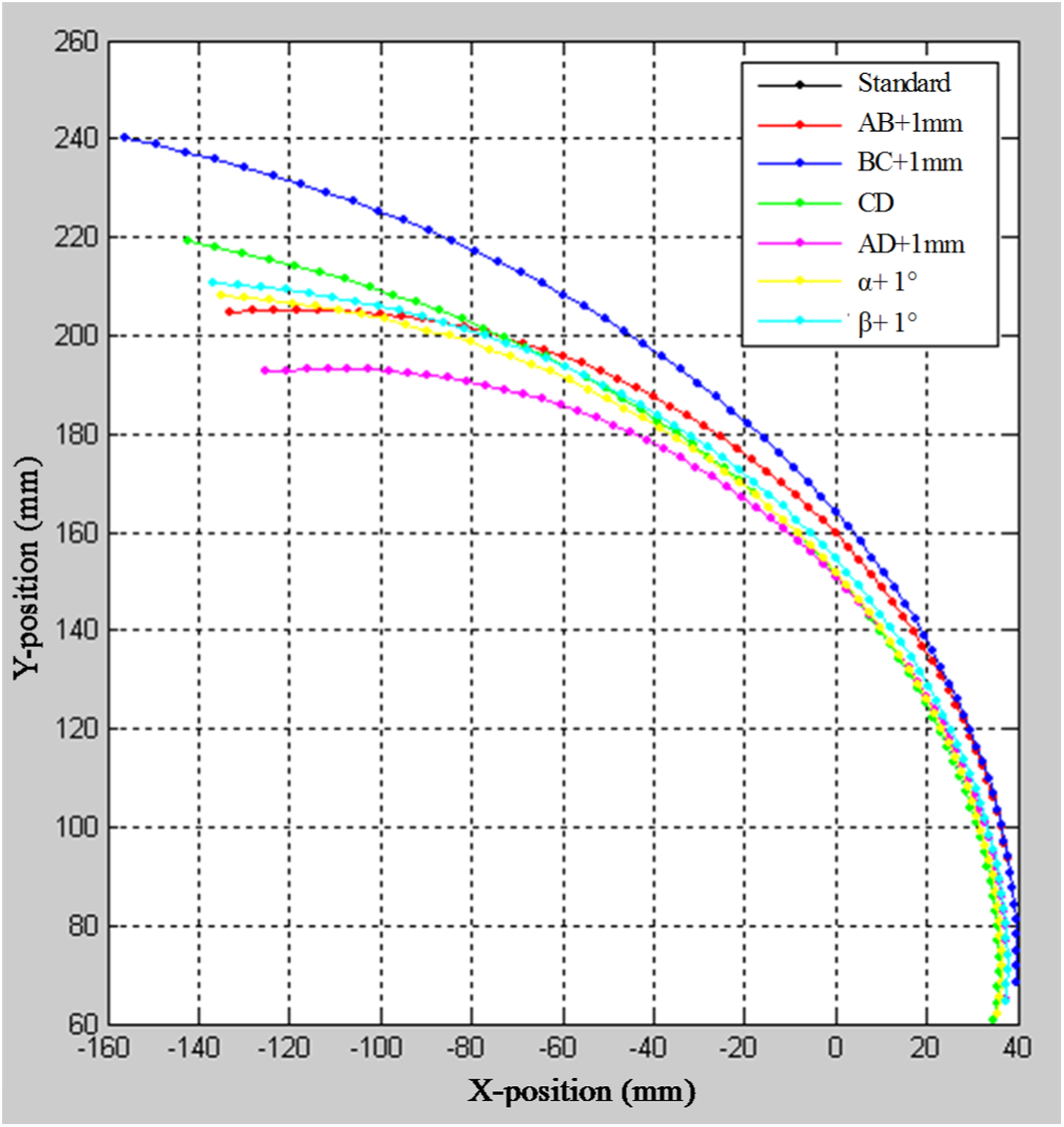
ICR curves under different rods length and different angle, X-position, Y-position are the coordinates of ICR, note that the standard line is overlapped by line of β + 1°. ICR: instantaneous center of rotation.
To find the relationship between these parameters and the position of the ICR, the above parameters were purposely changed. The red curve in Figure 4 is the ICR curve when the length of the AB rod extended to 76 mm. The other curves in Figure 4 are the ICR curve when adding 1 mm to the length of a specific rod. As shown in Figure 4, adding the length of AB and CD rods has little effect on the ICR curve. While adding the length of BC rod, the ICR is obviously higher than the standard position and moves to the left, which means higher stability 19 but less flexibility. Nevertheless, when adding the length of AD rod, the ICR becomes much more lower and moves to the right, which means poor stability but better flexibility. When adding the angle β, the position of the ICR is not changed, which means the same stability and flexibility as the standard knee joint. When adding the angle α, the ICR is lower than the standard which means better flexibility but poor stability. Therefore, the changes of the length of BC and AD rods in the four-bar linkage have greater influence on the ICR while the changes of other parameters have little influence, especially the change of the angle β.
By establishing constraints, this article calculated the length of the four rods to make sure that the designed PKJ has both proper stability and flexibility, and its instantaneous center is posterior to the load line at the heel-strike phase and prior to the load line at the toe-off phase, as shown in Figure 5.
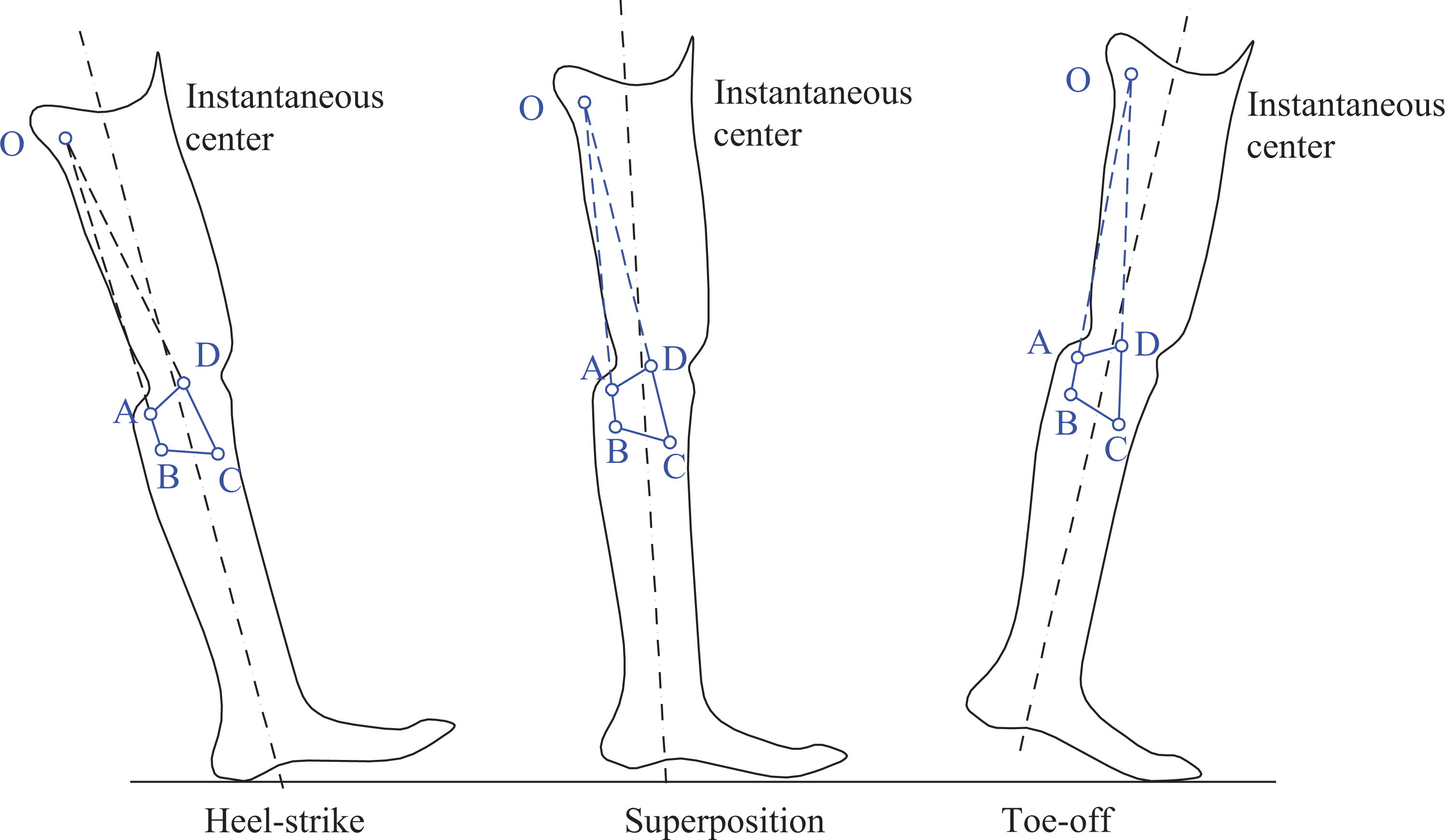
Principles of the instantaneous center calculation.
Gait simulation for the PKJ
Any relative movement between two components can be regarded as the instantaneous rotation around a fixed point in the space. In the human body, both scroll and slide are existed on the surface between two joints. 20 During walking, the length of thigh and shank changes and the speed of the ICR of the PKJ is time varying. The gait curve of the designed PKJ must be close to that of the healthy limb as much as possible. As shown in Figure 6, a big peak has occurred around point D which represents the maximum flexion of the knee joint. There is also a small peak at point B which indicates that a genuflex occurred during normal walking. This action guarantees people walking easier. However, the normal four-bar linkage knee joint cannot realize the small peak in the stance phase, as shown in Figure 6. This article, by installing a parallel spring on the rear connecting rod, makes its length variable and generates a buffer flexion angle ranging from 10° to 15° with the four-linkage structure. This rod is compressed only at the heel-strike phase. While in other phases like stance phase, the rod would be under tension, and, as a result, it keeps its original length without any deformation.

Knee angle curve of normal four-bar linkage PKJ, biological knee, and intended design. PKJ: prosthetic knee joint.
In order to implement the intended design shown in Figure 6, SolidWorks (Dassault Systèmes SOLIDWORKS Corp., Waltham, Massachusetts, USA) was used to build the model of the PKJ and ADAMS® (The MSC Software Inc., Newport Beach, California, USA), which was used to simulate the gait curve. The simulation was performed with the following steps: Import model from SOLIDWORKS to ADAMS Establish constraints Add spring, damper, and force
Add elasticity coefficient, damper coefficient, and preload for the spring and damper element. The damper coefficient is 4 N·S/mm and the preload is 50 N, while the elasticity coefficient is 400 N·S/mm and the preload is 50 N.
4. Simulation
5. Result outputting
In the environment of ADAMS, the angle curve of thigh and shank cannot be directly output; therefore, indirect method is employed. Select “Measure-Point” to Point in the Menu Bar of Build, choose two markers in one part, and then click θ in the cylindrical coordinates to carry out the measurement. With this method, the different angle–time curves of thigh and shank with horizontal line can be drawn. The knee angle curve is shown in Figure 7, which is drawn based on the curve calculation function in ADAMS by subtracting the corresponding points of the two curves.
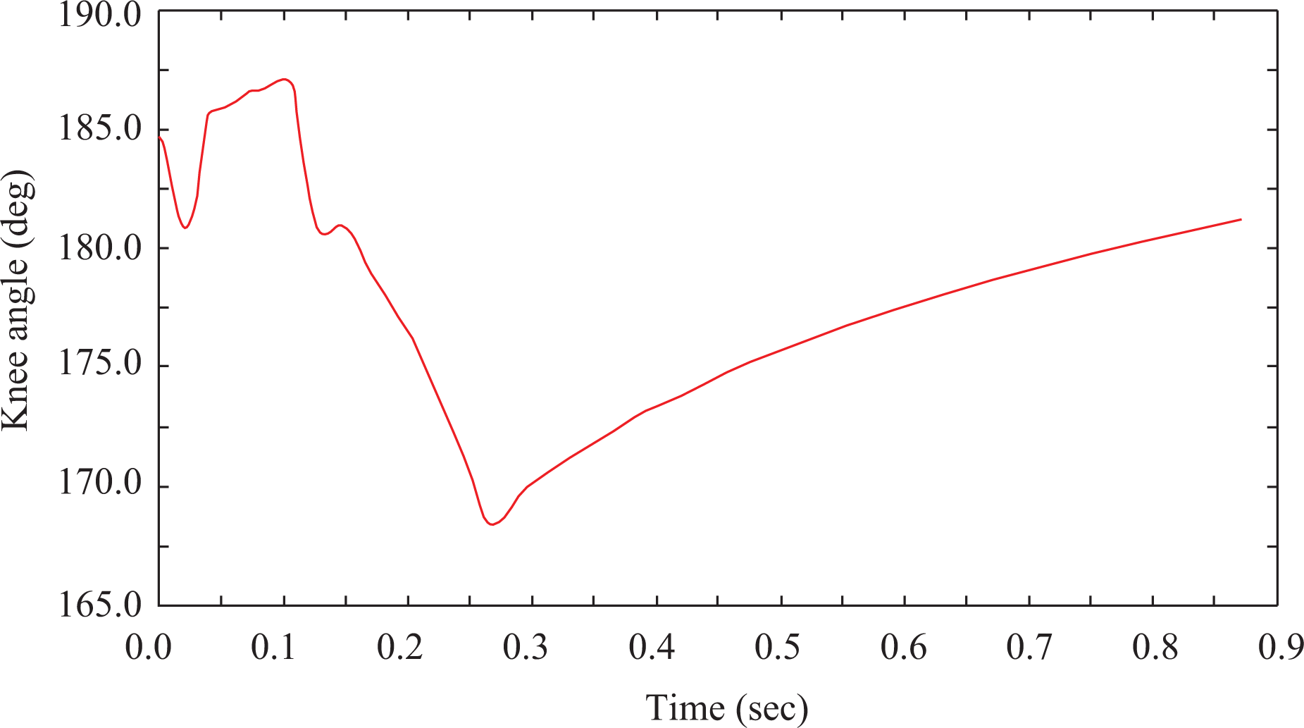
The simulation knee angle curve with ADAMS.
To calculate the spring camber influence on the buffer buckling angle of the knee joint, this article adds the camber of the spring by shortening the length of rear connecting rod continuously to calculate the variation of the angle between thigh and shank. The result of rubber mat under an 80 kg load is shown in Figure 8. The compression of the rubber mat is 9.28 mm, which is minor so that the maximum buckling angle of the knee joint can reach up to 15°.

The analysis results of rubber mat.
Calculation of bending angle
As shown in Figure 9, the bending angle of PKJ can reach up to 160°without any interference. The bending angle can either be measured in SolidWorks or in ADAMS by establishing an observing force with fixed thigh and shank.

The bending angle of the PKJ. PKJ: prosthetic knee joint.
Finite element analysis of the PKJ’s block
To analyze the deformation of the PKJ’s block statically, a 2500 N vertical force is exerted on the rotary component plane. Figure 10(a) shows that the resultant displacement is 0.2593 mm. Figure 10(b) shows that the maximum stress is 1.1765 × 10⁸ N/m2. The material of the block is 7075 aluminum alloy and that of the bolt bearing is alloy steel with the minimum safety factor of 4.29. The analysis results show that the stress and strain are within a safe range.

Results of finite element analysis. (a) The resultant displacement diagram. (b) The stress nephogram.
Experiment
When the parameters were determined from calculation and simulation, the prototype of the designed PKJ was fabricated with aluminum alloy. The weight of the designed PKJ is 791 g and the limit supporting weight is 100 kg. The length is 224 mm and the maximum buckling angle can reach to 15° with an elastic genuflex process. The maximum bending angle is 160° and the swing speed can be adjusted. With the prototype, benchtop testing and amputee walking experiments were conducted in this section.
Fatigue test
In order to verify the reliability of the designed PKJ, fatigue test was conducted for the PKJ. Figure 11(a) shows the tested knee joint in the fatigue test machine. The knee joint has to complete the late stance under a load of 1200 N for three million times. Furthermore, infrared flame scan equipment is used to detect where the fatigue often occurred, as shown in Figure 11(b), the brightest place of the weakest point. Two designed PKJs were under test, no damage was found after the fatigue test, and the temperature of the weakest point is 31°C, which is still within the acceptable range. Consequently, the reliability of the designed PKJ can satisfy the requirements.
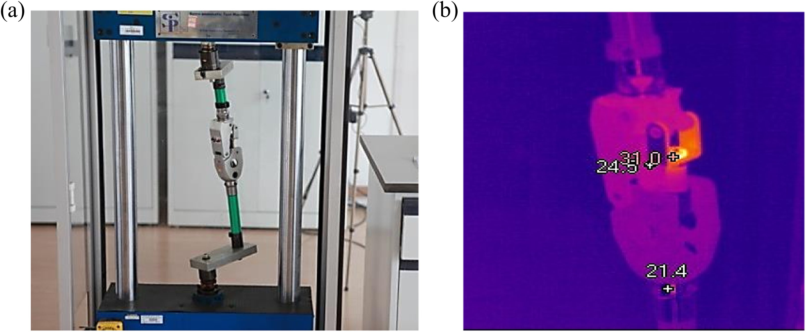
(a) Fatigue test workbench for the designed PKJ. (b) The infrared scan result after fatigue test, the temperature of the weakest point is 31°C. PKJ: prosthetic knee joint.
Gait analysis
The performance of the proposed PKJ was evaluated in gait experiments with an amputee (age 40, height 182 cm, and weight 83 kg). The subject was wearing the designed PKJ and had given informed consent to the investigations. Eight markers were pasted on the healthy side and the prosthetic leg, respectively. The gait curves of the amputee were recorded by VICON (Vicon Motion Systems Ltd., Oxford, UK) including six high-speed cameras. Figure 12 shows the gait curve of the designed PKJ including two peaks which are close to the gait of the healthy side. Figure 13 shows the ground reaction force curve of the PKJ with respect to the ground corresponding with the gait curve shown in Figure 12. Experimental results show that the gait curve of the designed PKJ basically corresponds with the gait curve of the healthy side and makes comfortable and portable sensory with no adverse reactions during walking.

The gait curves of the designed PKJ, the horizontal axis is the frame number at the sample frequency of 100 Hz. PKJ: prosthetic knee joint.
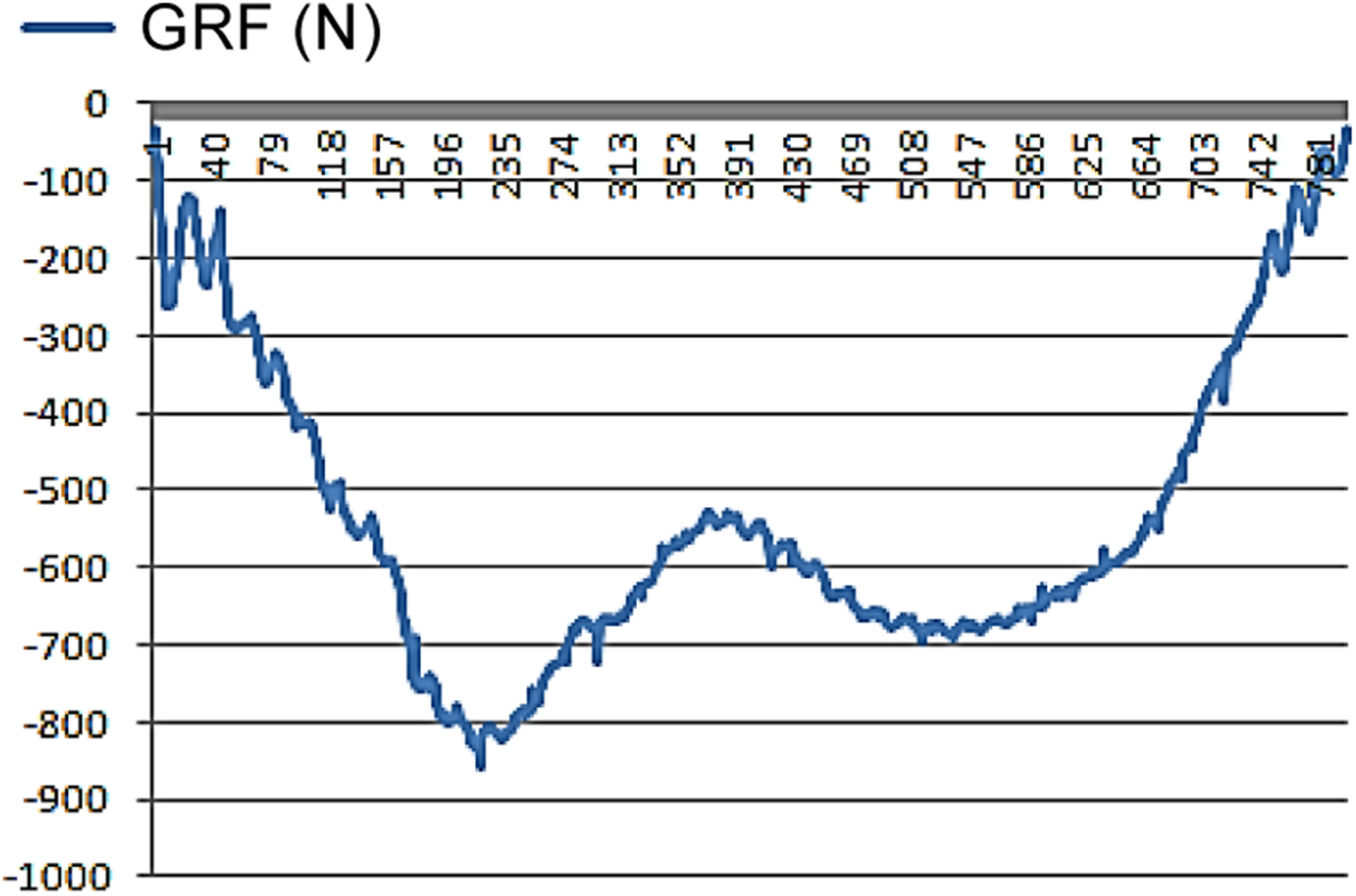
The ground reaction force of the designed PKJ, the horizontal axis is the frame number at the sample frequency of 1000 Hz. PKJ: prosthetic knee joint.
Conclusion
In this article, a four-bar linkage PKJ with a parallel spring and damper was proposed, with the parallel spring, the length of the connecting rod is variable, and a buffer flexion angle can be generated. Thus this design can absorb the impulsive force at the heel-strike phase and improve the stability of the stance phase. The damper is used to regulate the swing speed of the shank by regulating the two throttle valves, so that the PKJ can satisfy the demands of various amputees. Moreover, the influence of the four-bar linkage parameters on the stability was analyzed and the parameters were optimized, kinematic simulation of the ICR curve was conducted. The result shows that the consistency of the designed PKJ and biological knee, which demonstrates that the designed mechanism is feasible and reasonable. Finally, fatigue test and clinical gait analysis have been implemented. Experimental results show that no design and quality problems were found in the fatigue test. The wearing experiment results show that the gait curve is close to that of the healthy leg, and the designed PKJ makes comfortable and portable sensory with no adverse reactions during walking.
In summary, the current PKJ design offers the following advantages over available four-bar linkage PKJs. With a parallel spring, the length of the rear connecting rod is variable, which generates a buffer flexion angle to absorb the impulsive force; this feature makes the designed PKJ more closer to biological knee. The damper between thigh part and shank part is used to regulate the swing speed of the shank, so that the PKJ can satisfy the demands of various amputees.
Footnotes
Acknowledgments
We would like to thank Xu Jianguang at National Research Center for Rehabilitation Technical Aids for his valuable discussion with the design and pertinent opinions for the article. We would also like to thank Liu Ying at National Research Center for Rehabilitation Technical Aids for the data collecting and article polishing. Finally, we would like to thank all the staff who participated in the project at the National Research Center for Rehabilitation Technical Aids and for their support for the experiment.
Declaration of conflicting interests
The author(s) declared no potential conflicts of interest with respect to the research, authorship, and/or publication of this article.
Funding
The author(s) received no financial support for the research, authorship, and/or publication of this article.