
Abstract
During the motion of a knee joint, the instantaneous center of rotation (ICR) of the tibia relative to the femur is not fixed but moves along a curve decided by the joint structure. Adapting to wearer’s personalized knee joint structure is important to improve the wearing comfort and rehabilitation effect of the exoskeleton. The paper proposes a design method of a personalized knee rehabilitation exoskeleton with high human-machine compliance. Firstly, an instantaneous center curve (ICC) generation algorithm is proposed, which extracts feature points of the tibia from the medical images of the wearer’s knee joint, generates ICRs of the tibia at different knee joint angles, and then fits the ICRs into the ICC of the knee joint. Secondly, a four-bar linkage model for the knee joint is applied, and the structure parameters of the linkage are optimized by minimizing the deviations between the ICRs of the linkage and the wearer. Finally, a lower limb rehabilitation exoskeleton is implemented, adopting a lightweight transmission scheme using conjugate cams combined with Bowden cables. The experimental results show that the designed exoskeleton is lightweight and has small relative movement and small interaction forces with the wearer, realizing good wearing comfort and motion compliance.
Keywords
Introduction
Rehabilitation exoskeleton can improve the efficiency and effectiveness of the rehabilitation process and has been widely used in the field of medical rehabilitation. 1 When designing a rehabilitation exoskeleton, it is necessary to match the motion of the exoskeleton with the human body to ensure the comfort of wearing and the rehabilitation effect. Knee joint is the most complex joint in the human body. During the rotation of a knee joint, the tibia slides and rolls relative to the femur at the same time. 2 The ICR of the tibia is not fixed, but varies at different joint angles. All the ICRs form an ICC. In addition, because there are differences in body and joint structure between individuals, each person’s ICC is also unique and personalized. People of different heights and genders have different ICC shapes, resulting in different kinematic requirements for exoskeletons. Therefore, one of the key contents of lower limb rehabilitation exoskeleton design is how to achieve the personalized ICC of the wearer’s knee joint.
Early exoskeletons focused on assistive function and usually used fixed hinge type rotation axis, which could not well simulate the time-varying characteristics of the ICR of knee joint. Roboknee was such an exoskeleton developed by Yobotics company. It could judge wearer’s intention by knee joint angle and ground reaction force and provide assistance for stairs climbing and deep knee bending. 3 Beyl et al. 4 developed a knee rehabilitation exoskeleton, which was driven by pneumatic biomimetic muscles, to study the human-machine interaction of the knee joint under natural motion conditions and guide gait rehabilitation training of the lower limbs. Maeda et al. 5 studied a knee exoskeleton with variable stiffness based on a pneumatic biomimetic muscle control method, aiming to enhance human walking ability and reduce excessive muscle activity during walking. Wang et al. 6 proposed a lower limb rehabilitation exoskeleton driven by electric hydraulic cylinders. The use of the hydraulic cylinders made that the motion of the exoskeleton was relatively stable, and the rehabilitation parameters, such as motion speed and range, could be adjusted according to the patient’s rehabilitation plan to achieve personalized rehabilitation training. Shepertycky et al. 7 developed a lightweight backpack exoskeleton for assisting walking and energy harvesting. The experimental results showed that the exoskeleton reduced the walking metabolic expenditure of healthy male users by 2.5 ± 0.8% and converts the removed energy into 0.25 ± 0.02 W of power. Di Natali et al. 8 presented a biomimetic design of a flexible, modular, and reconfigurable pneumatic exoskeleton. This study evaluated the task-based assistance and human-machine interaction of the exoskeleton and found that the assistance generated was 26.6% of the hip joint drive, 9.3% of the knee drive, and 12.6% of the ankle drive. Penzlin et al. 9 proposed a parallel elastic driven active exoskeleton system that provided comprehensive motion support during gait circles. The integration of parallel elastic actuators into the hip joint reduced the peak driving torque of the hip joint by 31%, demonstrating the improvement of upright gait efficiency. Copilusi et al. 10 conducted experimental analysis on 30 healthy participants and 5 participants with motor nerve disorders, and obtained the angular change rules of the main joints of human (buttocks, knees, and ankles) and designed an exoskeleton made of kinematic linkages, whose core structures were two planal parallel mechanisms at the knee and ankle joints. The study conducted numerical simulations of the design process and verified the engineering feasibility of the exoskeleton. Pan et al. 11 designed a lightweight lower limb rehabilitation exoskeleton, with a weight of less than 16 kg. The thigh and the lower leg of the exoskeleton were infinitely adjustable, and the knee joint was directly driven by a motor installed on it. Hess-Coelho et al. 12 presented a dynamic design method of exoskeleton based on modular modeling, which had advantages in modifying the exoskeleton model, and could gradually improve the exoskeleton. Zhou et al. 13 designed a knee exoskeleton with series elastic actuator, which used a gear set and ball screws to drive the exoskeleton. This exoskeleton did not consider the personalized motion of the knee joint, but optimize the structural dimensions of the transmission mechanism based on gait biomechanics, ensuring stability and compactness of the exoskeleton, and ensuring a smaller peak force required during the gait cycle. Li at al. 14 developed an exoskeleton using a joint coupling mechanism. Each leg of the exoskeleton was driven by one motor. Because of the joint coupling mechanism, knee motion was activated through coupled motion of the hip or ankle. Experiments showed that the exoskeleton could achieve safe and natural walking.
Some studies have also considered the time-varying motion characteristics of the knee joint. Liao et al. 15 and Zhou et al. 16 developed a biomimetic knee exoskeleton for the purpose of physical assistance and rehabilitation. The knee joint was driven through a rack and link transmission, which allowed the femur to roll and slide on the tibia, being similar to the natural motion state of the knee joint. Zhou et al. 17 proposed a parallel model of knee exoskeleton with three active degrees of freedom on the sagittal plane based on the human ICR. The hip joint had one degree of freedom and the knee joint has two, being beneficial for matching the motion of the exoskeleton with the human knee joint. Niu et al. 18 developed a knee exoskeleton with a flexible five bar mechanism, which had two degrees of freedom on the sagittal plane and could adapt to the changing ICC of the human knee joint. The exoskeleton proposed by Jiang et al. 19 took into account the differences in knee joint ICR caused by the irregular shapes of the human knee joints among different individuals, and used a five-bar mechanism with two degrees of freedom to adapt to these differences. An optical 3D motion capture system was used to measure and calculate human walking gait and ICR of the knee joint. The size parameters of the five-bar mechanism were optimized to minimize the ICR error between the human body and the exoskeleton. The experimental results show that the motion trajectory of the exoskeleton is close to that of the human body, improving the wearing comfort. These exoskeletons made significant improvements in terms of motion compliance, but their mass and volume were relatively large.
Therefore, it is necessary to improve the performance and wearing comfort of knee exoskeletons by simultaneously considering in the design phase the time-varying characteristics of knee joint motion, the personalized joint structure of the wearer, as well as reducing the mass and volume of the exoskeleton.
In this paper, a personalized lightweight and small load knee rehabilitation exoskeleton is designed to match personalized ICC of the wearer. To achieve this goal, a personalized ICC generation method is proposed by extracting the feature points from the medical images of the wearer; Then a four-bar linkage knee joint model is adopted, and the structure parameters of the linkage are optimized by minimizing the deviation between the ICCs of the linkage and the wearer; A transmission scheme combining conjugate cams and Bowden cables is presented to reduce the weight and volume of the exoskeleton.
The main contribution of this study is that a novel design method for lower limb exoskeleton is proposed, which utilizes X-ray or MRI images of the knee joint of the specific wearer who wears the exoskeleton to personalize the exoskeleton design for him, matching the joint movements of the exoskeleton and the wearer, thereby improving the wearing comfort of the exoskeleton. This contribution may promote the application of exoskeletons in the field of rehabilitation by improving their comfort and performance. The remainder of this paper is organized as follows: Section “Generation of the ICC of the wearer’s knee joint” describes the ICC generation method according to the X-ray images of wearer’s knee joint; Section “The design of the four-bar linkage model of knee based on the ICC” advances the optimal design of the four-bar linkage of knee joint based on the ICC; Section “The implementation of the exoskeleton” gives the implementation of the exoskeleton; Section “Experiments and results” presents the ICR and wearing experiments and the results; Section “Conclusions” gives the conclusions.
Generation of the ICC of the wearer’s knee joint
The procedure of the ICC generation
To achieve personalized exoskeleton design, it is first necessary to obtain the personalized ICC of the tibia relative to the femur of the wearer during knee joint movement. As shown in Figure 1, the main procedure of the ICC generation is as follows:
Step 1: Obtain the X-ray images of the wearer’s knee joint, which provide the positions and postures of the wearer’s tibia and femur at different joint angles from 0° to 90° on the sagittal plane.
Step 2: For each X-ray image, extract the contour curves of the tibia and femur to generate contour image. All contour images form a contour image set CIS.
Step 3: For each image in CIS, generate feature points for the tibial contour curve based on the feature point generation algorithm presented in Section “Feature point generation.”
Step 4: Fit the corresponding feature points in the contour images and generate feature point trajectory curves; Based on the feature point trajectory curves, for the knee joint at any specific angle, create its ICR using an intersection normal method provided in Section “Generation of ICRs and ICC.”
Step 5: Fit all ICRs to generate the ICC of the joint.

The flowchart of ICC generation.
Knee joint image acquisition and contour image generation
In the study, the wearer is a healthy male aged 25 years old, with a height of 168 cm, a weight of 58 kg, and a leg length of 78 cm. The X-ray photos of his left knee joint on the sagittal plane are taken. The knee joint angle changes from 0° to 90°. Take a photo every 10° and a total of 10 photos are taken.
For each X-ray image as shown in Figure 2(a), the Sobel operator edge detection algorithm and contour tracking algorithm are adopted to extract the outer contours of the tibia and femur, as shown in Figure 2(b) and (c). Thus 10 contour images of the tibia and femur are obtained. The contour curves of the tibia (TC) and femur (FC) are expressed as NURBS curves. By applying geometric registration on the FCs of all the contour images, 10 contour images are scaled, translated, and rotated with the FCs having the same size and being in the same position. By this means, 10 contour images are aligned with the same scale.
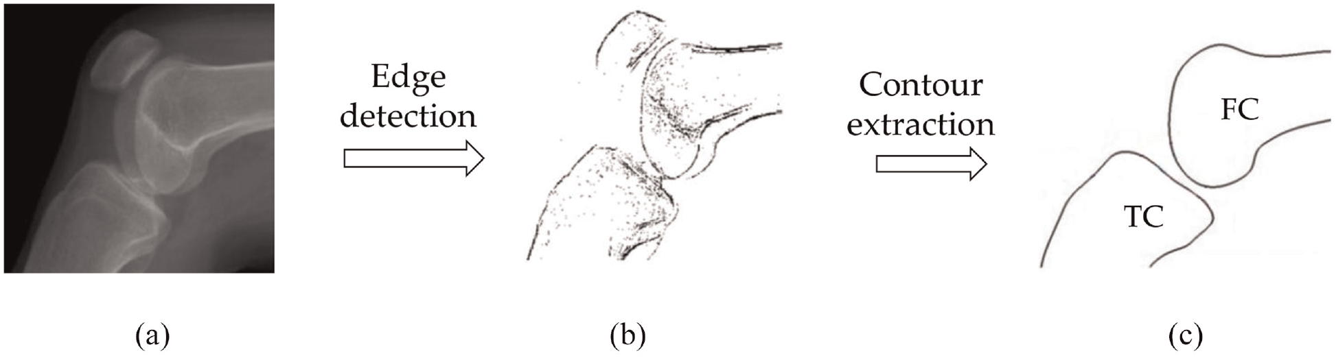
Contour image generation of the knee joint: (a) Original X-Ray image, (b) Image with edges detected, and (c) Contour image.
Feature point generation
Three fixed points on the tibia contour that moves together with the tibia when the joint rotates, namely A, B, and C shown in Figure 3, are extracted as feature points. Feature point generation (FPG) algorithm is proposed to extract the three feature points on each TC.

Feature point extraction.
As shown in Figure 3, on a contour image, suppose

The steps of the FPG algorithm are as follows:
Step 1: Divide the TC into two parts by the line GtGf. Along the direction of
Step 2: Create line A1B1 and intersect it with the TC. A1, B1, A2, B2 are the intersect points.
Step 3: If the |A1A2| and |B1B2| are both less than the accuracy threshold ε = 10−3 mm, go to Setp 6.
Step 4: Calculate the curve parameters u a 1, u a 2, u b 1, u b 2 of A1, A2, B1, B2 on the TC. Set
u a = (u a 1 + u a 2)/2.0,
u b = (u b 1 + u b 2)/2.0,
get points A = TC(u a ) and B = TC(u b ) at the parameters u a and u b on the TC.
Step 5: Set A1 = A, B1 = B, go to Step 2.
Step 6: Create a line BC with ∠ABC = 30° and BC intersecting with TC at point C.
Step 7: Output the feature points A, B, C.
Extract the feature points for each TC. Because the TCs generated from X-ray images have only differences in posture while the differences in shape are very small, the feature points generated by the FPG algorithm can be regarded as fixed points on the TCs.
Generation of ICRs and ICC
After the feature points are generated, fit the same feature points on the 10 contour images and three feature trajectory curves, namely Tr a , Tr b , and Tr c , are obtained, as shown in Figure 4.

The ICR and ICC generation.
An intersection normal method is proposed based on the feature trajectory curves to determine the ICRs. Suppose the ICR of TC i is O i . Suppose A i , B i , and C i are the feature points of TCi. A i , B i , and C i are on Tr a , Tr b , and Tr c , respectively. Create the normal N a of Tr a through point A i , the normal N b of Tr b through point B i , and the normal N c of Tr c through point C i . O ab , O bc , and O ac are the intersection points of N a and N b , N b and N c , and N a and N c , respectively. Because Tr a , Tr b , and Tr c are the trajectories of the feature points A, B, and C, respectively, O ab , O bc , and O ac should overlap at the rotation center of the tibia in theory. However, due to the existence of many factors such as differences in medical images, inaccuracy of image processing, and inconsistency of feature points, etc., they actually do not overlap. O i is obtained according to equation (1):

Where
In order to describe the ICRs and ICC clearly, establish the coordinate system on the sagittal plane as follows. Set the first ICR O1 as the origin. Suppose A, B, and C are the feature points of the TC on the contour image at the joint angle of 0°. Set BO1 as the Y axis. The X axis is perpendicular to the Y axis and points backwards. The ICRs and ICC of the wearer are shown in Table 1 and Figure 5, respectively.
The values of ten ICRs.

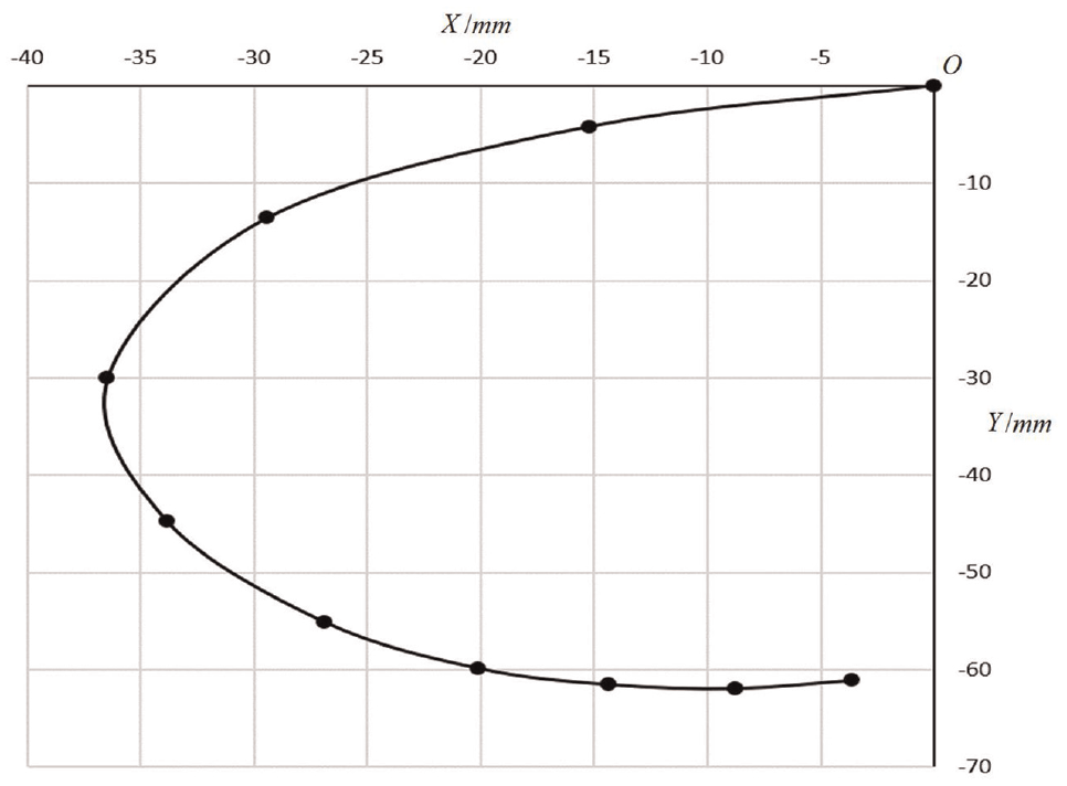
The ICRs and ICC of the wearer.
The design of the four-bar linkage model of knee based on the ICC
As mentioned above, the motion of the knee joint has a complex form with both rolling and sliding on the articular surface. Because four-bar linkages can realize this form of motion well, we use a planar four-bar linkage to simulate the knee joint. In order to ensure the wearing comfort of the exoskeleton, the ICC of the four-bar linkage should be as consistent as possible with the ICC of the knee joint obtained in Section “Generation of the ICC of the wearer’s knee joint.”
As shown in Figure 6, ABDC is a four-bar linkage. Rod AB is fixed on the thigh of the exoskeleton and CD is fixed on the lower leg. To simplify the design and make the linkage more compact and be aligned with the knee joint as much as possible, we suppose A is on the Y axis. To determine the structure of the four-bar linkage, six structure parameters need to be specified, namely
(1) The design objective function

The four-bar linkage model of knee joint.
According to Section “Generation of ICRs and ICC,” the ICC of the wearer is obtained by fitting the 10 ICRs. In order to ensure that the ICRs of the exoskeleton are as consistent as possible with those of the wearer during joint motion, the optimization goal of the four-bar linkage is to minimize the sum of the distances between the ICRs of the exoskeleton and the wearer at the corresponding positions, which is shown in equation (2):

Where
The design vector

(2) Constraint conditions
The coordinates of A and B are:
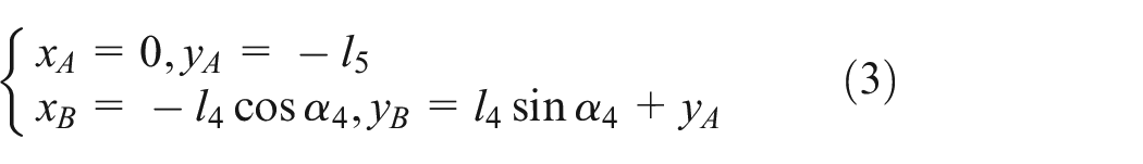
At the ith position, where i = 1–10, the coordinates of C and D are:

Since Q is on the straight lines DA and CB, so

Then the coordinate

According to equation (3) to (6),
At the ith position, project the quadrilateral ABDC toward the Y axis and X axis respectively, then equation (7) can be obtained.

By equation (7),
At the first position,

The angle difference of the lower leg at two adjacent ICRs is shown in Table 1, then

Other constraint conditions include the rod length conditions of a four-bar linkage:
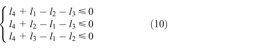
Where
And the boundary conditions of the design variables which are used to limit the size of the linkage:
(3) Optimization result
Set the initial values of the design variables as:

The optimization result is (Table 2):
Design result.
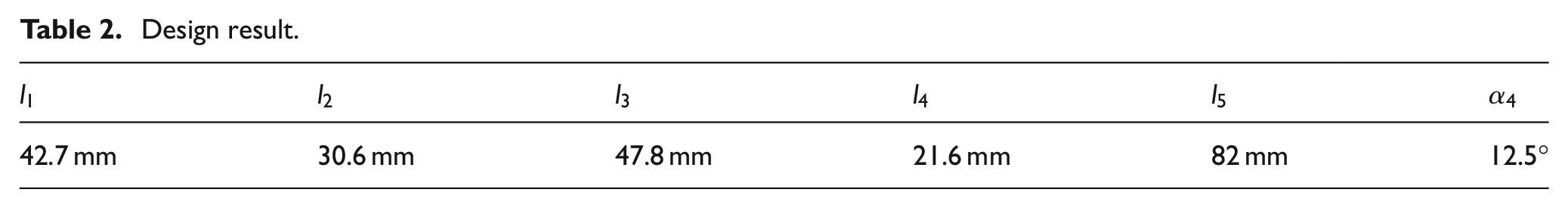
Figure 7 shows the ICRs of the optimized exoskeleton and the wearer. The maximal difference between them is 4.94 mm which is at the joint angle of 90°.
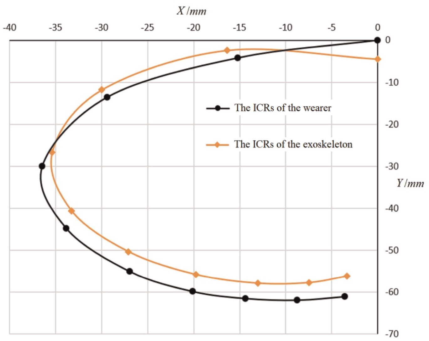
The ICRs and ICC of the exoskeleton and the wearer.
The knee joint based on the four-bar linkage is shown in Figure 8. The rotation angle range of the lower leg is 0°–90°. In order to solve the problem of interference, rod BD is designed as a circular arc shape.

The knee joint based on the four-bar linkage.
The implementation of the exoskeleton
Figure 9 is the lower limb rehabilitation exoskeleton designed in the study, which includes a waist fixation module, two leg modules, and a transmission system. The waist fixation module is mounted two driving motors and a control system. Each leg module is composed of a thigh, thigh straps, slider springs, the four-bar linkage, a lower leg, lower leg straps, and rotating pulleys. The hip joint is a passive joint that can rotate in the horizontal and the sagittal planes, and the ankle joint can rotate on the sagittal plane.

The lower limb rehabilitation exoskeleton.
Lead screw drive and gear drive are common transmission methods used by exoskeleton,19–22 which brings large volume, heavy weight, and large rotational inertia to the knee joint and makes it inconvenient for wearing. Consider that Bowden cable drive can effectively solve these problems, 23 we use Bowden cables to achieve transmission from the motor to the four-bar linkage, which reduces the weight of the exoskeleton.
As shown in Figure 10, two Bowden cables, the flexion cable and the extension cable which controls the bending and the stretching of the knee joint respectively, are used. Two slider springs are mounted on the Bowden cables to adjust the system stiffness. The upper ends of the Bowden cables are wrapped around a so-called conjugate cam and the lower ends are connected to the lower leg. In Figure 10,

The Bowden cable transmission.
The angle of the knee joint is controlled by the Bowden cable lengths which are adjusted by the conjugate cam. The conjugate cam is actually a pair of fixed coaxial cams as shown in Figure 11, around which the flexion cable and the extension cable wrap in different directions respectively. By the conjugate cam, the lengths of the flexion and extension cables are synchronized during the motion of the knee joint. Figure 12 shows the relationships between the lengths of the Bowden cables and the angle of the knee joint. The conjugate cam is designed based on this relationship. By this method, synchronous control of the flexion cable and the extension cable by a single motor is achieved, ensuring that the Bowden cables are always in a tensioned state during the rotation of the knee joint.
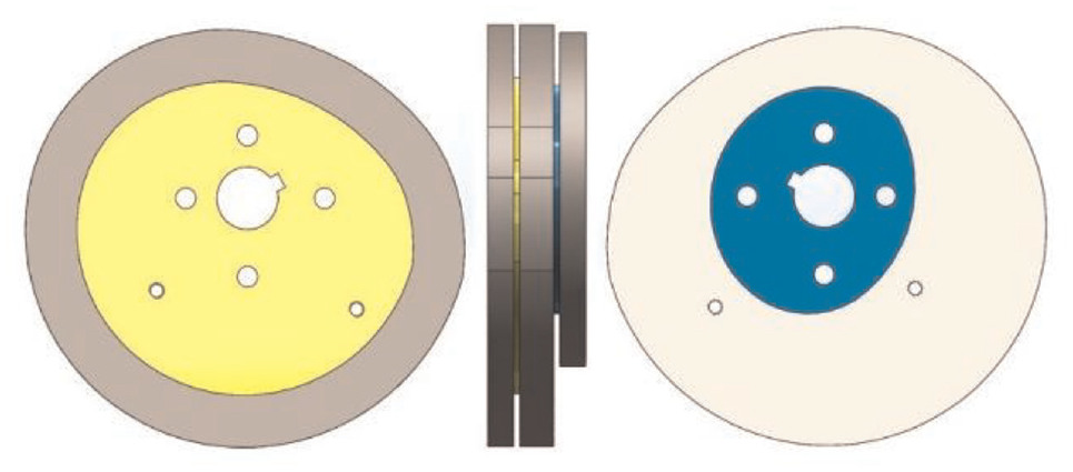
The structure of the conjugate cam.

The relationships between the lengths of the Bowden cables and the joint angle.
Using the conjugate cam combined with the Bowden cable transmission, the proposed exoskeleton is lightweight with a weight of 16.8 kg, which is lighter than some typical exoskeletons such as Ekso and ReWalk, as well as a major part of the exoskeletons listed in Table 1 in Rupal et al. 24 There is still room for further optimization and weight reduction of the exoskeleton. Meanwhile, compared to most exoskeletons in Rupal et al., 24 the exoskeleton has fewer devices mounted at the knee joints, reducing joint volume and making the device easier to wear.
Experiments and results
To verify the effectiveness of the proposed method, we conducted ICR and wearing experiments to validate the motion capability and the human-machine compliance of the exoskeleton. The ICR experiments tested the knee joint movement at different speeds. The purpose was to verify whether the exoskeleton’s movement ability could meet the speed requirement of rehabilitation pace, and to check how the actual ICRs of the exoskeleton match those of the wearer. The wearing experiments were designed to verify human-machine compliance by testing the difference in human gaits before and after wearing the exoskeleton, as well as the magnitude of human-machine interaction forces during the walking process.
In the experiments, the lower limb exoskeleton developed in the study was used. Since the exoskeleton is bilateral symmetry, the left leg is selected for the experiments. An angle encoder with a PPR of 2500 was mounted on each conjugate cam axis to detect the rotation angles of the cam. Two IMUs were installed on each lower leg, as shown in Figure 9, to measure the gait data of the lower leg on the sagittal plane. The acceleration resolution of the IMU is 0.0005 g, the angular velocity resolution is 0.61°/s and the dynamic measurement accuracy is 0.1°. On each binding belt, two pressure sensors were mounted at the front and back of the leg, respectively, to record the interaction forces between the leg and the exoskeleton. The range of the pressure sensors is 5 g–1 kg, with a resolution of 0.1 g.
The ICR experiments
The ICR experiments were carried out to obtain the motion curves and the ICRs of the knee joint of the exoskeleton. During the experiment, the exoskeleton was fixed on a frame, with the thighs being fixed in vertical states, and the lower leg of the exoskeleton was driven to rotate around the joint, as shown in Figure 13. IMU data were collected to analysis the motion of the lower leg, including its angle, angular velocity, angular acceleration, and ICRs.

The dynamic response experiment.
To test the motion capability of the exoskeleton at different speeds, the motor was set to different speeds, namely 1000, 1200, 1500, and 1800 rpm. Recorded the rotations of the knee joint from 0° to 60° and then 60° to 0° at different speeds. The motion curves of the knee joint are shown in Figure 14. It can be seen that during the rotations of the knee joint, the motions were smooth without any pause or impact. When the motor speed was 1500 rpm, the speed of the left leg reached one step per 1.5 s, which is approximately the normal walking speed of humans. Considering that the rehabilitation walking speed is generally slower than the normal walking speed, the exoskeleton can meet the speed requirements of rehabilitation pace.
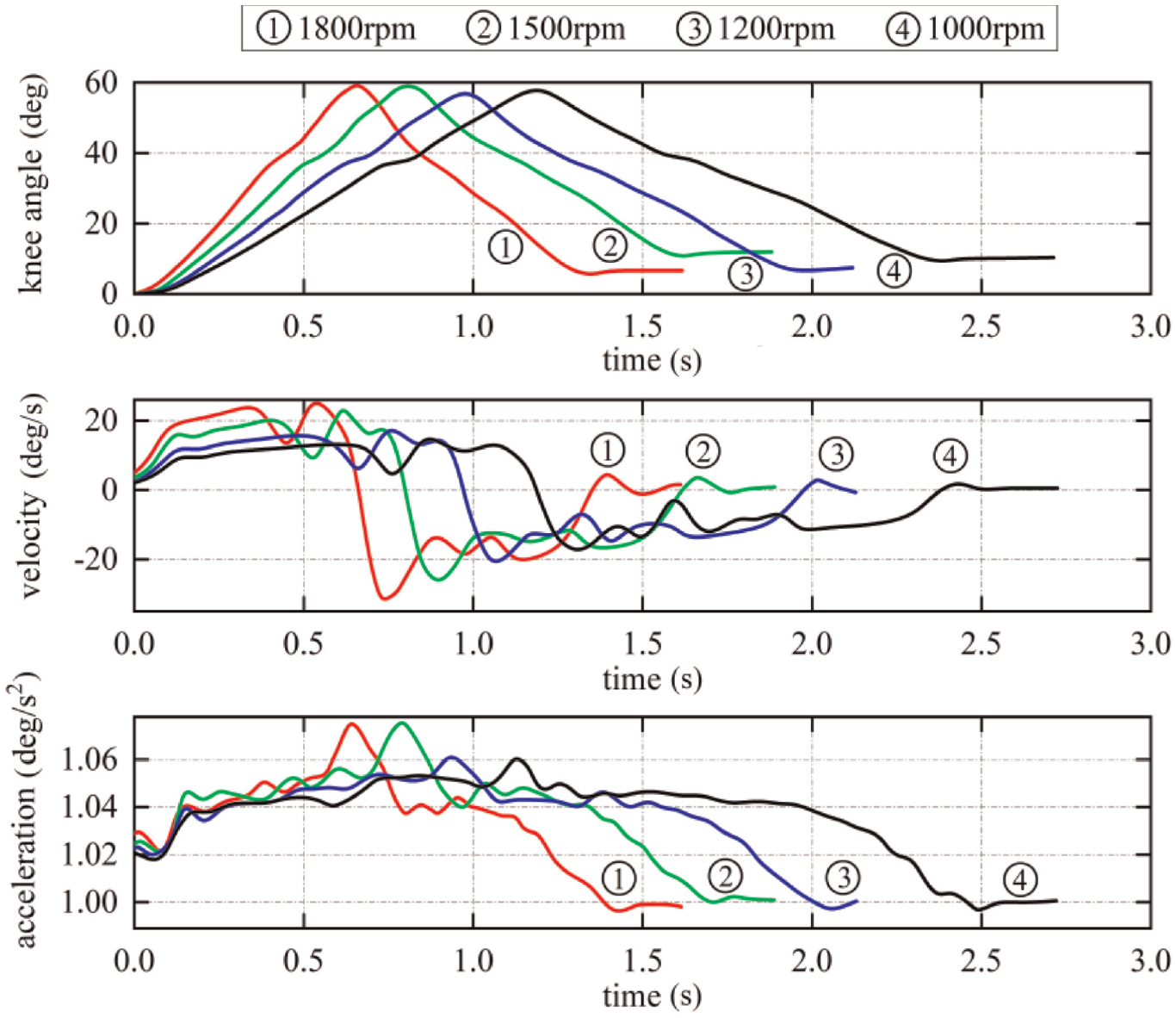
The motion curves of the lower leg under different speeds.
To obtain the real ICRs of the exoskeleton, the motor was set to 1500 rpm and the knee joint rotated repeatedly from 0° to 90°. By the angular velocities and accelerations of two IMUs and their installation positions on the lower leg, the angles of the lower leg and its absolute ICRs can be deduced. Since the thigh was fixed, the absolute ICRs were also the ICRs of the lower leg relative to the thigh. Figure 15 shows the real ICRs and ICC of the lower leg. It can be seen that the real ICC of the exoskeleton matches well with that of the wearer. The maximal difference between the real ICRs and the designed ICRs of the exoskeleton is 3.2 mm, which occurred at the joint angle of 80°, and the maximal difference between the real ICRs of the exoskeleton and those of the wearer is 5.4 mm, which occurred at the joint angle of 0°. The differences may come from the errors of design method, measurement, manufacturing, and assembly. The differences are small and the flexible constraints between the human body and the exoskeleton can tolerate them, thus achieving good human-machine compliance.

The ICRs and the ICCs of the lower leg.
The wearing experiments
Other important manifestations of human-machine compliance include the changes in gait and the interaction forces between human body and the exoskeleton after wearing the exoskeleton.
In order to test the gait changes before and after wearing, the gait data of the participant wearing and non-wearing the exoskeleton are compared. The participant of the gait tests was the one who provided the X-ray images of the knee joint. The data collection of non-wearing gait experiment was completed using a Nokov optical motion capture equipment. The collection experiment was conducted in an indoor area of 3 m × 5 m, with six infrared cameras symmetrically placed. Reflective marker points were pasted on the key points of the lower limbs of the wearer. When the wearer walked, the cameras collected gait data at a frequency of 340 Hz. The collection of wearing gait data was completed by the angle encoder and the IMUs on the exoskeleton. During the wearing gait experiment, the wearer did not add any active force on the lower leg and was driven to walk by the exoskeleton. The exoskeleton moved with the same step frequency, stride and maximal joint angle as in the non-wearing experiment. In order to increase walking stability, an auxiliary cart was used, as shown in Figure 16.
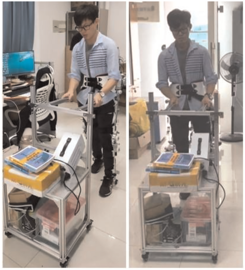
The human-machine compliance experiment.
Figure 17 shows the knee joint angle curves of the participant in wearing and non-wearing tests. It can be seen that the wearing gait curve is smooth and there is no significant sudden change of speed. The phases of the knee joint angle curves in wearing and non-wearing experiments keep good consistency in each gait cycle. The maximal knee joint angles in the non-wearing experiment are slightly greater than those in the wearing experiment, which may be due to the influence of inertial forces when the exoskeleton drove the human body. The small difference between the wearing and non-wearing gait curves reflects a small relative motion between the human body and the exoskeleton.

The angle curves of the knee joint.
To verify the interaction forces between the human body and the exoskeleton, we conducted wearing force experiments. The interaction forces are influenced by many factors, including structural non-compliance, the intensity of rehabilitation training, and so on. When the exoskeleton is not powered, the interaction forces generated by the wearer’s walking best reflect the structural compliance between the exoskeleton and the wearer. In the wearing force tests, the wearers walked without any driving force from the exoskeleton. The interaction forces were recorded by the pressure sensors mounted on the binding belts. There were four binding belts on each leg connecting the leg with the exoskeleton, as shown in Figure 9. Two pressure sensors were mounted on each belt, with one at the front of the leg and one at the back of the leg. The initial tightening force on the pressure sensors was approximately 400 g. We chose the data of the sensors on two binding belts near the knee joint for analysis. Two wearers participated the experiments. Wearer 1 was the one who provided the X-ray images. Wearer 2 was a male, with a height of 180 cm, a weight of 75 kg, and a leg length of 86 cm. The exoskeleton developed by the study has adjustable leg lengths. For different wearers, the lengths of the thighs and the lower legs were adjusted to better match the wearer’s heights. In this way, the structure of the exoskeleton knee joint was the main factor affecting the interaction forces.
Figure 18(a) shows the pressure curves of the thighs of wearer 1 and wearer 2. At the front of the thigh, the maximum pressure value of wearer 1 is 490 g, the minimum value is 345 g, and the fluctuation range is 145 g; For wearer 2, the values are 518, 309, and 209 g, respectively. At the back of the thigh, the maximum pressure of wearer 1 is 465 g, the minimum value is 308 g, and the fluctuation range is 157 g; For wearer 2, the values are 534, 262, and 272 g, respectively. The maximum and the minimum resultant forces that wearer 1 beard at the thigh binding belt are 92 and −148 g respectively (A negative sign indicates a backward force), with a fluctuation range of 240 g; For wearer 2, the values are 175, −243, and 418 g, respectively.

Interaction forces of different wearers: (a) interaction forces of the thighs and (b) interaction forces of the lower legs.
Figure 18(b) shows the pressure curves of the lower legs. At the front of the lower leg, the maximum pressure value of wearer 1 is 544 g, the minimum value is 296 g, and the fluctuation range is 248 g; For wearer 2, the values are 625, 276, and 349 g, respectively. At the back of the lower leg, the maximum pressure of wearer 1 is 750 g, the minimum value is 202 g, and the fluctuation range is 548 g; For wearer 2, the values are 874, 53, and 821 g, respectively. The maximum and the minimum resultant forces of wearer 1 are 429 and −330 g respectively, with a fluctuation range of 759 g; For wearer 2, the values are 543, −460, and 1003 g, respectively.
Table 3 shows the results of the interaction force analysis. It can be seen that wearer 1, as the personalized design object, experienced small interaction forces during walking. Meanwhile, compared to wearer 2 who was not the personalized design object, the interaction forces are smaller and the fluctuation range are at least 32% smaller.
The results of the interaction forces.

Conclusions
This study proposes a lower limb rehabilitation exoskeleton design method that adapts to the personalized characteristics of the ICC of the wearer’s knee joint. The method extracts features points of the tibia and the femur from medical images of the wearer’s knee joint, and then uses these feature points to generate the ICRs of the tibia relative to the femur, by which the ICC of the lower leg is created. A four-bar linkage is designed to simulate the ICC of the human knee joint and obtain the same motion as the wearer’s knee joint as much as possible. The designed rehabilitation exoskeleton uses conjugate cam combined with Bowden cable transmission to drive the knee joint, achieving synchronous control of the flexion, and extension motion of the knee joint with a single driving motor. Through the ICR and wearing experiments of the implemented exoskeleton, it is concluded that the designed four-bar linkage-based knee exoskeleton has similar ICRs and ICC, small relative movement and small interaction forces with the wearer, realizing good wearing comfort and human-machine compliance.
Future works will mainly focus on exoskeleton control methods and rehabilitation strategies based on the interaction forces.
Patents
There are two China invention patents resulting from the study: A Design Method of Personalized Knee Rehabilitation Exoskeleton with High Human-machine Compliance (ZL 2021 1 0610808.1), and A Lightweight Lower Limb Rehabilitation Exoskeleton (ZL 2021 1 0944210.6).
Footnotes
Acknowledgements
The authors thank all the project partners who contributed to the presented study.
Handling Editor: Chun-Ta Chen
Author contributions
Conceptualization, X.P. and Y.H.; methodology, X.P. and Y.Z.; software, Y.Z. and Z.D.; validation, Y.P. and F.C.; investigation, X.P. and Y.Z.; data curation, Z.D.; manuscript writing and review, X.P. and Y.Z.; visualization, Y.H. and F.C.; project administration, X.P.. All authors have read and agreed to the published version of the manuscript.
Declaration of conflicting interests
The author(s) declared no potential conflicts of interest with respect to the research, authorship, and/or publication of this article.
Funding
The author(s) disclosed receipt of the following financial support for the research, authorship, and/or publication of this article: The research was supported by Shenzhen Natural Science Fund (the Stable Support Plan Program 20220807145745001) and 2023 Guangxi University Young and Middle-aged Teachers Scientific Research Basic Ability Improvement Project (2023KY1134).
Ethics approval
The study was conducted in accordance with the Declaration of Helsinki, and approved by the Ethics Committee of Shenzhen University (protocol code M202200479 approved on 21 July 2022).
Informed consent
Informed consent was obtained from all subjects involved in the study.
Data availability statement
Not applicable.