
Abstract
To improve the operating performance of robots’ end-effector, a humanoid robot hand based on coupling four-bar linkage was designed. An improved transmission system was proposed for the base joint of the thumb. Thus, a far greater motion range and more reasonable layout of the palm were obtained. Moreover, the mathematical model for kinematics simulation was presented based on the Assur linkage group theory to verify and optimize the proposed structure. To research the motion relationships between the fingers and the object in the process of grasping object, the grasping analysis of multi-finger manipulation was presented based on contact kinematics. Finally, a prototype of the humanoid robot hand was produced by a three-dimensional printer, and a kinematics simulation example and the workspace solving of the humanoid robot hand were carried out. The results showed that the velocities of finger joints approximately met the proportion relationship 1:1:1, which accorded with the grasping law of the human hand. In addition, the large workspace, reasonable layout, and good manipulability of the humanoid robot hand were verified.
Introduction
Nowadays, due to the excellent characteristics, such as intelligent control, operation flexibility, and high degree of humanoid,1–3 robots have been applied in many fields, such as medical science, 4 equipment maintenance, 5 aviation, 6 explosive ordnance disposal (EOD), 7 and industrial production. 8 The operating performance of a robot end-effector plays an important role in completing the complex tasks. Most of the robot end-effectors are designed for the specific tasks and objects, while they have much limitation. Thus, the design of the humanoid robot hand with finger joints, multi-degrees of freedom, and certain perception functions has been an active area.9,10
At present, many researchers have been working on the development of the humanoid robot hand and one of the important issues is its structure design. Zhang et al. 11 proposed a sensitivity of the torque sensor with a four-bar link shape for the robot manipulator, and the experimental results show that the sensitivity can be increased 3.5 times without sacrificing stiffness. Kargov et al. 12 presented a new hydraulic driving method for the innovative artificial hand. The force and speed performance of the robot hand were kept steady through controlling the pressure of flow. After that, there appeared multi-motor to drive the fingers of the humanoid robot hand. For example, Jin et al. 13 present a new underwater manipulator design based on four-bar linkage with multi-motor, and the robot can be used as gathering things such as starfish on the sea floor. Actually, each human hand should have 18 degrees of freedom for grasping objects flexibly and steadily. To realize that, Cipriani et al. 14 presented a robot hand named SmartHand, which was composed of 16 degrees of freedom. The robot hand was designed by tendon drive principle; thus, it did more functions similar to the muscles of a human finger.
For a multi-finger manipulation system, the kinematics model of multi-finger manipulation is a very complex problem and many researchers have attempted to solve it. Salisbury and John 15 proposed the concept of grasping matrixes to establish the velocity relationships between the object and finger tip for the first time. Thus, the movement control of the object could be realized through the movement control of finger joints indirectly. Kerr and Roth 16 pointed out that instantaneous contact freedom could be equivalent to spherical joint under the contact mode of the friction point. Then, the contact point moved along the object and finger tip during the grasping process, which could be merged in the uniform equation. Reis et al. 17 addressed the problem of kinematic modeling and control design of a multi-finger robot hand, and the experiments were carried out with a three-fingered robot hand executing grasping and manipulation tasks of soft objects.
The workspace of the robot hand was put forward by Roth 18 for the first time in 1975. It has attracted much interest in the robot academia. Borras and Dollar 19 explored the geometric design of dexterous three-fingered robotic hands for maximizing precision manipulation workspace. The research showed that a proper parameter design for underactuated hand can achieve up to 50% of the workspace of a fully actuated hand. Zhong and Zhu 20 proposed a new method of numerical algorithm, and they selected variable combinations to solve the workspace of the robot hand. Liang et al. 21 adopted the Monte Carlo method to simulate and analyze the workspace of tomato harvest robot. The results showed that the method achieved a better solution speed. Wang et al. 22 discussed the stable workspace of a hand foot–integrated quadruped walking robot. An automated computational system of the stable workspace was developed in combination with MATLAB, VB, and SolidWorks software programs. Xue et al. 23 proposed a scanning method to generate the workspace of Schunk Anthromorph robot hand. However, the accuracy of this method relied on the scanning steps.
Although many research results had been achieved in the robot hand field, they have some common disadvantages summarized as follows. First, few methods are applied to the kinematics and dynamics analysis of coupling four-bar linkage. How to obtain a bigger interaction space between the thumb and the rest of the fingers is still a puzzle to many researchers. Second, the computation of multi-finger manipulation kinematics is quite complex. Besides, the expressions based on the instantaneous kinematics of velocity are simple. Finally, few researches have focused on the workspace of the robot hand and the influence factors of robot hand grasping performance.
To tackle the above problems, a humanoid robot hand was designed based on the transmission mechanism of coupling four-bar linkage. Because the humanoid robot hand is mainly used to complete grasping operation, the kinematics analysis of multi-finger manipulation is presented based on the contact kinematics. Finally, a kinematics simulation example and workspace solving are carried out. The designed humanoid robot hand has proved reasonable layout and good operating performance.
The rest of this article is organized as follows: The structure design of the humanoid robot hand is proposed in detail in section “Structure design of humanoid robot hand.” Grasping analysis of multi-finger manipulation is proposed in section “Grasping analysis of multi-finger manipulation.” The kinematics simulation example and workspace solving are carried out and discussed in section “Kinematics simulation example and the workspace solving.” Conclusions and future work are summarized in section “Conclusion and future work.”
Structure design of humanoid robot hand
According to the thoughts of bionic design, the humanoid robot hand is composed of palm, fingers (thumb, index finger, middle finger, ring finger, and little finger), wrist, and driving components settled in the palm. Moreover, coupling four-bar linkage is applied to the transmission mechanism of each finger. This transmission mode has the advantages of small size, compact structure, and bigger output force.3,24 However, reliable connection and high assembly accuracy between the linkages are the key factors of stable grasping for the humanoid robot hand. Thus, these factors are needed to be concerned in the design process.
Coupling four-bar linkage
The coupling principle of two four-bar linkages is presented in Figure 1(a), and the base joint is actuated by the motor. Furthermore, the middle joint and far joint are actuated by the knuckles and linkages. Thus, traditional kinematics methods are not suitable for analyzing it, such as D-H method and planar Cartesian kinematics. Here, Assur linkage group theory presented by Accyp, 25 as one of the most effective method for analyzing planar linkage mechanism, is applied to solve the kinematics problem of coupling four-bar linkage. The principle of Assur linkage group theory consists of three types of basic linkage group 26 as shown in Figure 2. According to the theory, the coupling four-bar linkage of the finger can be disassembled as I and II level linkage groups as shown in Figure 1(b). The kinematics models of I and II level mechanisms are presented as Appendices 1 and 2, respectively.

The structure and principle diagram of coupling four-bar linkage: (a) the coupling principle of two four-bar linkages, (b) linkage groups in coupling four-bar linkage, and (c) the movement sketch of coupling four-bar linkage corresponding to finger features.
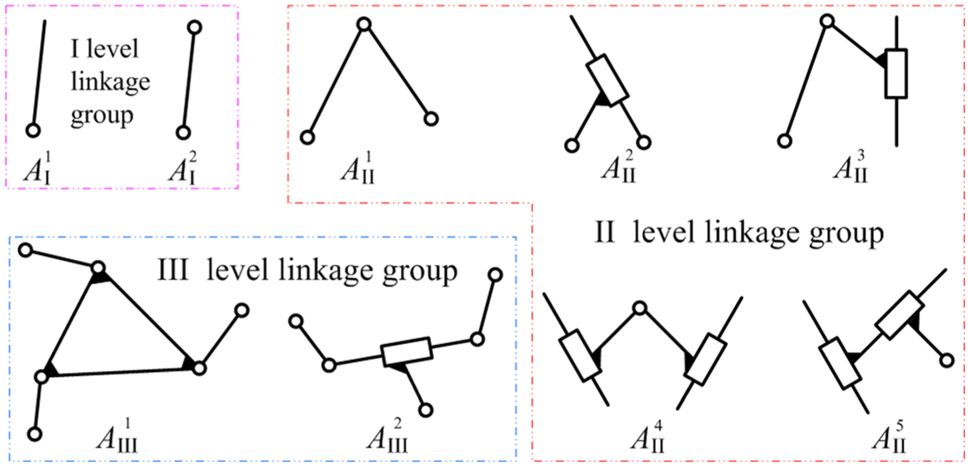
Three types of basic linkage group.
Structure design of humanoid robot hand
From the research status, the robot hands have some characteristics, such as simple structure, humanoid hand, and excellent performance. While a robot hand could hardly contain all of them, there appear contradictions on balancing the structure and performance of a robot hand. To alleviate the prominent contradiction, this article applies coupling four-bar linkage mechanism in the five-finger mechanism design as shown in Figure 1(c). The parameters of palm arrangement are further optimized to achieve a simple and compact robot hand. The thumb is indispensable and the most flexible among the five fingers. Therefore, 2 degrees of freedoms for base joint, namely, bending and side pendulum, are driven by two motors, and they are controlled synchronously co-rotation or inversion. The transmission system of the base joint is designed as shown in Figure 3. Furthermore, the explode diagram of the thumb is established, and Figure 4 demonstrates the whole mechanism of the thumb.
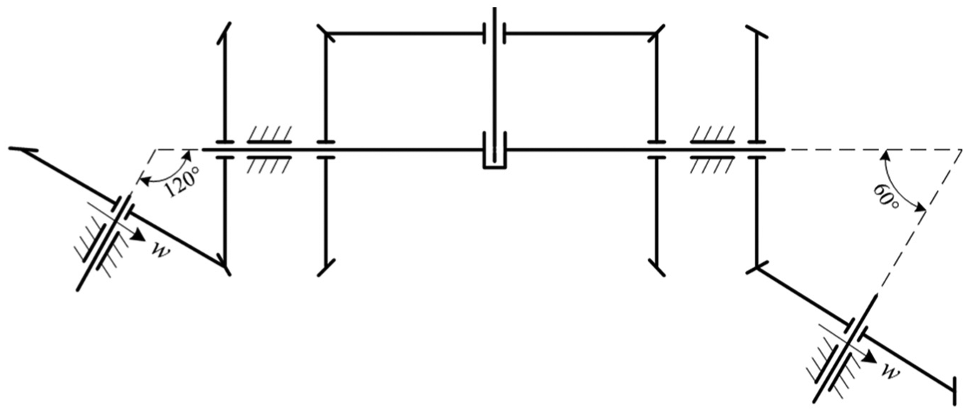
The transmission system of base joint of thumb.
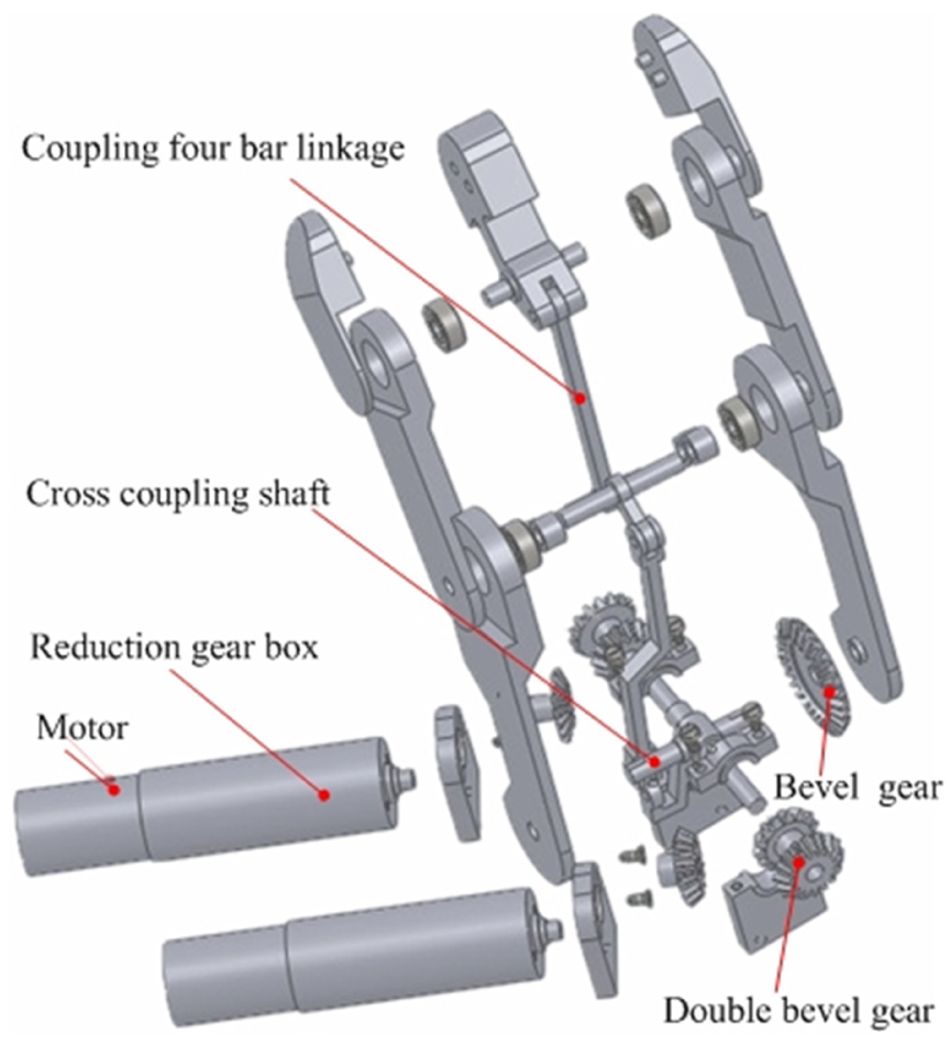
The explode diagram of thumb.
The parameters of finger length and palm size are referred to the proportional of the human hand. Through sample analysis and optimization, the proportional of near, middle, and far knuckles should be close to 2:1.35:1. The prototype of the humanoid robot hand has been developed as shown in Figure 5.

The prototype of humanoid robot hand.
Grasping analysis of multi-finger manipulation
There exist rolling and sliding when multi-finger robot hand grasps objects. Thus, under the condition of the existing frictional contact points, accurate contact locations of finger tips have an important influence on completing grasping task. Suppose the surfaces of finger tips are sphere shapes, we can conclude that the contact points rotate around the center of the sphere finger tips in the grasping process. In other words, it could be regarded as the interior rotation motion of the fingers and does not change with the positions of the actual contact points on the surface of finger tips. Based on the contact kinematics, analysis of two-finger and five-finger grasping chains is presented as follows.
Analysis of two-finger grasping chain
Under the premise of planar grasping, the grasping coordinates of the two fingers are established when the random object is grasped as shown in Figure 6. According to the mode of finger tip rolls over the object surface, there exist 2 degrees of freedoms of virtual finger tip. The grasping chain coordinates of the two fingers are established, and then a closed kinematic chain between the fingers and the object is formed as shown in Figure 7. To describe conveniently, define the two fingers as the master finger and slave finger, respectively. Suppose the base coordinates of the two fingers are

The coordinate of two-finger grasping.
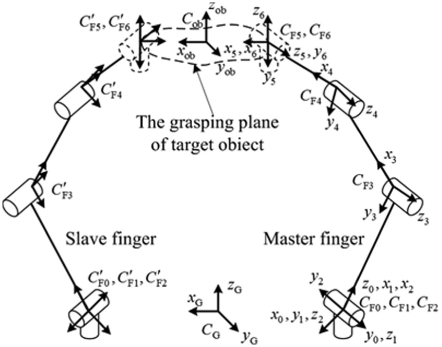
The closed grasping chain of two fingers.
As shown in Figure 7, although


Then,


In the equations,

In the matrixes,
Then


Analysis of five-finger grasping chain
Force balance and closed kinematic chain can be satisfied by two-finger grasping chain analysis. On this basis, to satisfy force closure grasping, resist external interference, and improve grasping stability, the contact points should be increased. Then, the grasping chain coordinates of the five fingers can be proposed as shown in Figure 8.

The coordinates of five-finger grasping chain.
The base coordinates of the five fingers are defined as


The coordinates of finger tips.
In the equations,

According to the kinematics equations of single finger, the coordinate transformation matrixes of middle finger tip can be calculated as follows

Based on the middle finger tip position, the given matrixes such as


According to the transmission principle of coupling four-bar linkage, the kinematics parameters of the middle knuckle are determined by finger tip, and the contact evaluation between the object and middle knuckle is not been presented.
Kinematics simulation example and the workspace solving
Kinematics simulation example
According to the recent research status, Yang et al. 3 and Yu 24 proposed that the middle and far joint velocities of the robot hand finger should approximately meet the proportion relationship 1:1. To imitate the grasping law of the human hand, studies and experiments are carried out for the proportion relationship of the human finger joints using data glove. The result shows that the velocities of the human finger joints approximately meet proportion relationship 1:1:1. Thus, we take the result as a design target of joints kinematics. To verify the proposed structure feasibly, the index finger is taken as an example to simulate the movement relationship. The example is based on the mathematical model of I and II level mechanisms which are provided in Appendices 1 and 2, respectively. The flowchart of kinematics simulation is presented as shown in Figure 10.
The flowchart of kinematics simulation.
In this example, the position of the base joint is set at the origin and the velocity of the base joint is set as 2.7°/s uniformly. The angular velocities and accelerations of each index finger joint can be presented as shown in Figures 11 and 12, respectively.
The velocities of index finger joints.
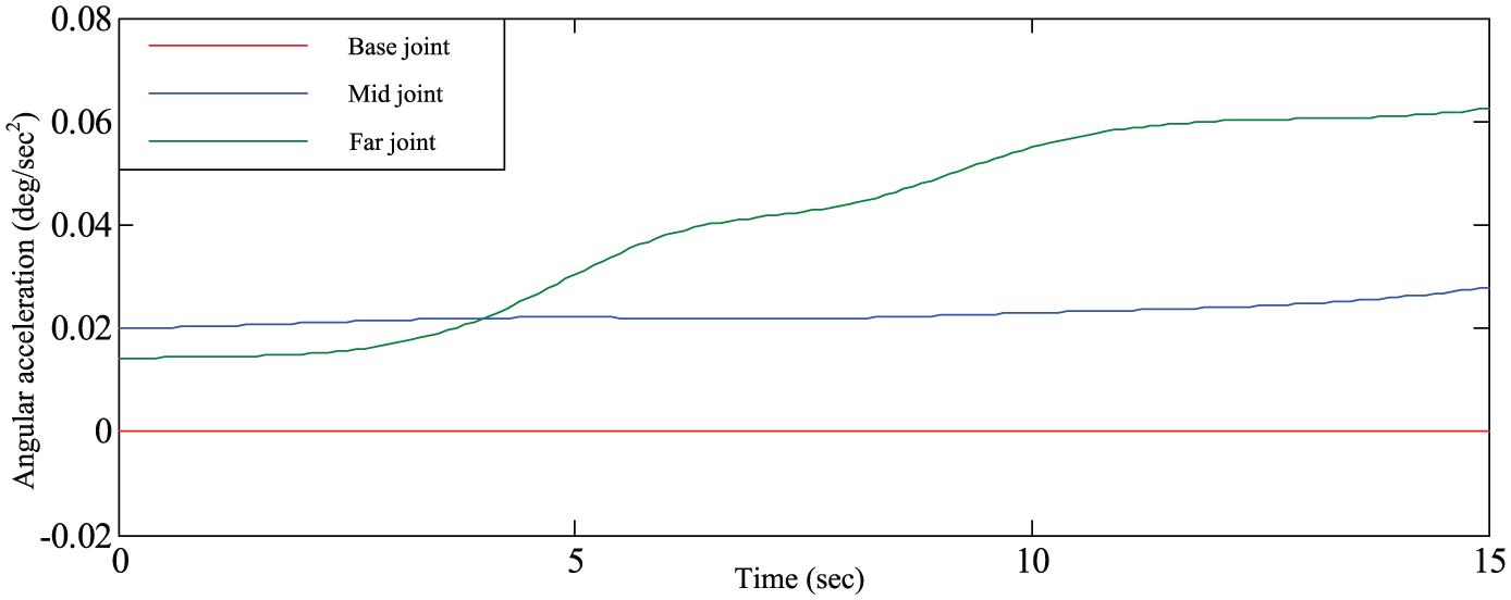
The angular accelerations of index finger joints.
The workspace solving
The workspace of the humanoid robot hand is decided by the parameters of lengths, rotation angles, and layout of the fingers. To improve the operating performance of the humanoid robot hand, large workspace and interaction space are urgent concerning problems. Based on the grasping analysis of multi-finger manipulation described in section “Grasping analysis of multi-finger manipulation,” the workspace of the humanoid robot hand is solved by the software of MATLAB as shown in Figure 13. Furthermore, the sketch map of the grasping range is presented by the legend of three-dimensional (3D) model of the humanoid robot hand as shown in Figure 14. After that, the interaction space of the thumb relative to the rest of the fingers can be calculated as shown in Figure 15. In addition, the basic function of the humanoid robot hand is grasping the objects effectively and steadily. To verify the grasping performance and the workspace of the humanoid robot hand, the results of grasping objects are shown in Figure 16.

The workspace of humanoid robot hand.

Sketch map of grasping range.

The gestures of grasping objects.

The interaction space of thumb relative to the rest fingers.
Summarization and discussion
Through simulating, the movement of the index finger and the proposed kinematics of coupling four-bar linkage are verified. The results can therefore be summarized and discussed as follows.
The movement is inputted from the base joint uniformly, so the angular velocity and angular acceleration of the base joint can be consistent. However, the angular velocities of the middle joint and far joint change differently due to the coupling linkages. They are changing from 2.5 to 2.81°/s and from 2.42 to 2.87°/s, respectively, within acceptable range as shown in Figure 11. Moreover, the angular accelerations of the far joint fluctuate greater than the middle joint as shown in Figure 12. In the simulation, the fluctuations of the middle joint and far joint change small and smoothly. The fluctuations would bring unstable and nonlinear movement, which could not be avoided by coupling linkage kinematics. Thus, the velocities of the finger joints approximately meet the proportion relationship 1:1:1, and the proposed structure of the robot hand is humanoid.
By solving the workspace of the humanoid robot hand, big workplace can be obtained as shown in Figure 13, which can be summarized as 284 cm3. Besides, the interaction space of the thumb relative to the index finger and middle finger reaches 1.18 × 10² and 1.01 × 102 cm3, respectively, as shown in Figure 15. Therefore, the humanoid robot hand is provided with good manipulability and practicability, as shown in Figure 16. According to the workspace of the humanoid robot hand shown in Figure 13 and the tests, a series of object shapes have better enveloping curves, such as cylinder (diameter, 36–97.8 mm), balls (diameter, 43–108 mm), and sheet (thickness, 5–68 mm). Furthermore, the results show that the layout and the parameters of the fingers are reasonable.
Conclusion and future work
A humanoid robot hand based on the coupling four-bar linkage was designed and the prototype was developed. Moreover, a kinematics simulation example and the workspace solving were presented. The simulation results illustrated that the velocities of the finger joints approximately met the proportion relationship 1:1:1 and could satisfy the design requirement of the humanoid robot hand. The experiment results showed that the layout and the parameters of the fingers were reasonable, and the humanoid robot hand was designed with good manipulability and practicability.
Ongoing and future work will focus on the dynamic analysis, grasping plan, and control system to make the humanoid robot hand more intelligent. Furthermore, the practical application of the humanoid robot hand is also an important research for the authors.
Footnotes
Appendix 1
Appendix 2
Academic Editor: David R Salgado
Declaration of conflicting interests
The author(s) declared no potential conflicts of interest with respect to the research, authorship, and/or publication of this article.
Funding
The author(s) disclosed receipt of the following financial support for the research, authorship, and/or publication of this article: This research was supported by the National Natural Science Foundation of Jiangsu Province (no. BK20151144), Discipline Frontier Research Project (no. 2015XKQY10), and Priority Academic Program Development of Jiangsu Higher Education Institutions (PAPD).