
Abstract
The end effector characterizing a flipping–cutting way is designed firstly for picking spherical fruits with a good universality, which is mainly composed of three parts such as a clamping mechanism, a flipping mechanism, and a cutting mechanism. Subsequently, the kinematics simulation for the clamping mechanism, flipping mechanism, and cutting mechanism will be implemented by mathematical models and the ADAMS software, and results reflected through them are consistent with each other, thus presenting the feasibility of the structural scheme and two models. On the basis of scheme and results of models, the sample of the end effector is manufactured. Finally, picking experiments in a lab will be also conducted in view of diverse indexes, such as the successful grabbing action, flipping–cutting action, flipping–breaking action, average fruit picking time, success rate, and damage rate. It is drawn from experimental results that the success rate of grabbing is 100%, and a success rate for picking is over 80%. An average picking time is about 9.6s, and very few fruits are damaged. Therefore, such a scheme is feasible, further presenting a good reference for designing the entire robot in a field of picking diverse spherical fruits.
Introduction
As an important part of production chain in the entire agriculture, fruit and vegetable harvesting usually requires a lot of manpower, resources, and time because of the strong seasonality, high labor intensity, and high production costs. 1 Also, the aging of the agricultural population and decrease in the proportion of young workers in rural areas will be a fact. 2 The harvesting methods depending on manual ways will be unsuitable for the modern agricultural production. The harvesting robots for picking fruits and vegetables must characterize a future trend in agriculture, which is quite crucial for liberating labor productivity, improving harvesting efficiency, and reducing harvesting costs. 3
Diverse picking robots have been developed in their respective fields by scholars, thus yielding a large number of robots and corresponding end effectors for strawberries, 4 –6 oranges, 7 –9 navel oranges, 10 –12 , apples, 13 –18 kiwifruit, 19 –21 tomatoes, 22 –25 eggplants, 26,27 cucumbers, and so on. As a terminal element directly contacting fruits and vegetables, the universality, practicality, and success rate of an end effector play a decisive role in the performance of picking robots. 28 Currently, the end effector can be classified into two categories if picking and separating methods are considered, such as rigid 29 and flexible 30 separation types. Of those, cutting tools such as scissors, blades, and saws are usually utilized to cut fruit stems after grabbing the fruit, which is so-called rigid separation method. 29 This method is universal for fruits and vegetables with strong binding force between the fruit and stem, such as citrus 7 –9 and cucumber. 31 –33 However, it is not easy to determine the cutting position of the fruit stem. Additional concerns on damage to crop branches and vines during the cutting process should be considered, and the accuracy of it is also required to be high. Considering the flexible one, 30 the fruit is always separated from its stem by twisting, folding, and pulling ways after grasping the fruit by the end effector. Such a type is mainly used to pick fruits and vegetables that their joints are fragile such as the apple 13 –18 and kiwi. 19 –21 At the same time, higher requirements for control on actuators and greater torques are necessary.
Combining characteristics of existing schemes and advantages of two separated ways, the end effector with a flipping–cutting way is designed, thus achieving the coherent action for picking such as grabbing, flipping–cutting, resetting, and unloading actions. Specifically, the overall design, the analysis for working principles, simulation models, and experiments will be implemented for establishing a more suitable end effector with a good universality in a field of picking diverse spherical fruits, such as the apple, citrus, and kiwi. The details will be given in next sections gradually.
The structural scheme and working principle
To achieve the flipping–cutting function and a good universality for picking diverse fruits, the end effector developed here is mainly composed of four parts (A: clamping mechanism; B: flipping mechanism; C: cutting mechanism; D: control system), and the overall scheme is demonstrated in Figure 1. The structural schemes for its clamping mechanism, flipping mechanism, and cutting mechanism are shown in Figures 2 to 4, respectively.

The overall structure.

The structural scheme of the clamping mechanism.

The structural scheme of the flipping mechanism.

The structural scheme of the cutting mechanism.
As shown in Figures 1 and 2, the clamping mechanism (A) is mainly composed of V-shaped finger (A-1), resistive film pressure sensor (A-2), silicone (A-3), connecting rod (A-4), frame (A-5), ball screw (A-6), lifting nut (A-7), stepping motor (A-8), and so on. Of those, the lower part of the V-shaped finger is hinged with the top of the frame. The middle part of the V-shaped finger is connected with the lifting nut by a connecting rod. The silicone is attached to the inside of the V-shaped finger. The resistive film pressure sensor is located at a position between the silicone and the right V-shaped finger. Installing at the bottom of the frame, the output shaft of the stepping motor is associated with the screw nut mechanism. The output torque of the stepping motor is controlled by the signal of the control system. The suitable torque is used to drive the V-shaped finger to grab the fruit through the movement of the screw nut. Essentially, such a V-shaped clamping mechanism with two fingers is driven by a motor, and it is suitable for grabbing fruits with different shapes and sizes on the basis of increasing the contact area between the finger and the fruit.
As shown in Figures 1 and 3, the flipping mechanism mainly contains the flipping baffle (B-1), I-frame (B-2), electric push rod (B-3), and base (B-4). The upper surface of the flipping baffle is fixed with the bottom of the frame in the clamping mechanism. The side part of the flipping baffle is connected with the I-frame with the pin. One end of the I-frame is hinged with the base. The electric push rod is fixed in the base, and it is hinged with the bottom of the flipping baffle. The stroke of the electric push rod will be adjusted by the control system for realizing the flipping movement.
The micromotor (C-1), mounting seat (C-2), crank (C-3), tool mounting slot (C-4), connecting rod (C-5), upper blade (C-6), ball bar (C-7), ball limiting slot (C-8), and lower blade (C-9) will be worked together to achieve the cutting task of cutting mechanism(C), as demonstrated in Figures 1 and 4. For a design instance, the upper and lower blades are linear single-blade serrated ones. The ball bar is arranged in the ball limiting slot between two blades. Also, the sliding movement of the upper blade relative to the lower one through the ball bar will be achieved. One side of the upper blade is successively associated with the connecting rod, the crank, and the micromotor. The micromotor is located above the right V-shaped finger by mounting seat. The output torque of the micromotor will be controlled by signals from the control system, and rotation of the crank and the connecting rod could be also achieved by such a torque through the output shaft of the micromotor. The reciprocating straight motion of the blade can be further realized. Therefore, such a structural scheme fusing the cutting and flipping mechanisms is possible to pick fruits effectively and universally.
The position and pose of the target fruit will be captured by a visual system continuously, and the position and pose of the robotic arm can be adjusted according to results of recognition and location. Further combining above structures and their functions, the end effector starts to work, and the picking process of spherical fruit is shown in Figure 5. Firstly, the clamping mechanism starts to work. The lifting nut will be moved up by the movement of the ball screw driven by the stepping motor, further pushing the connecting rod for pulling the V-shaped finger to envelope and clamp fruits. The stepping motor will be stopped to work if the positive pressure drawn from the resistive film pressure sensor has been reached to the safety threshold. Subsequently, the flipping and cutting mechanisms will be worked synchronously. The rotation of the larger and smaller cams will be also achieved by the driven ability of the micromotor, further obtaining a motion of reciprocating straight of the upper blade around the lower one. Moreover, the electric push rod will be moved up, and the flipping baffle will be pushed by this movement, thus generating a flipping angle to the lower left direction for the whole clamping mechanism. During such a flipping process, the cutting mechanism and the fruit stem are matched to cut off the fruit stem. Completing separation of the fruit and its stem, the cutting mechanism stops cutting, and the electric push rod will be reset. Following the movement of the robotic arm, the fruit will be further grabbed by the clamping mechanism until transferring it to the fruit collection area. Finally, the clamping mechanism is reset, and the fruit will be disengaged to complete the picking operation for a single fruit.

The picking process for the spherical fruit: (a) initial stage; (b) grabbing fruit; (c) flipping and cutting; and (d) turning and disengaging fruit.
Kinematic simulation analysis
Mathematical models
For determining the input–output relationship in the clamping mechanism, the kinematics analysis of each component will be reflected through mathematical models. The screw nut mechanism will be simplified to a planar guide rail slider mechanism, and it is assumed that the guide rail is fixed to the frame. Structures of two V-shaped fingers are completely same and symmetrically arranged along the screw nut. Therefore, the one side of the clamping mechanism is taken for the kinematics analysis, and its structure diagram is shown in Figure 6.

The simplified diagram of a single claw.
In Figure 6, O is the origin. Lengths of L 1, L 2, and L 3 are 53, 60, and 80 mm, respectively. θ 1 represents the angle between OB with length L 1 and vertical direction. θ 2 is the angle between BC with length L 2 and vertical direction. θ 3 denotes the angle between AB with length L 3 and vertical direction. The slider A is the originally driven component that is moved vertically along the guide rail, and its distance (length of OM) between the initial position and the original point O is defined as 60 mm. The one side of the gripper of the clamping mechanism can be characterized as a closed vector triangle, yielding that

and the projection of equation (1) on the X and Y axes can be followed as

Taking the first derivative of time in equation (2), the first-order motion differential equation of this three-bar mechanism can be given by
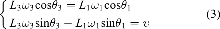
Similarly, the second-order motion differential equation will be expressed as

where ω 1 and ω 3 are angular velocities of rod OB and rod AB, respectively. υ characterizes the speed of the slider A. α 1 and α 3 are angular accelerations of rod OB and rod AB. a represents the acceleration of slider A.
Two V-shaped claws are arranged symmetrically along the central line, and the grabbing range of the clamping mechanism can be determined by the displacement of a single finger. According to features in Figure 6 and equation (2), the displacement of point C is followed as

and the grabbing range of the clamping mechanism will be given by

in which Xc and Yc are displacements of point C in X and Y axis directions. θ 2 is the angle of between the distal phalanx BC of the finger and the vertical direction, and it can be characterized by

Specifically, d 1 is the thickness of the frame with a value of 12 mm in an instance. h is the stroke of the lead screw ranged from 0 mm to 30 mm. The variable rate of θ 1 and θ 3 relative to time t can be determined if the lifting speed of the screw nut is defined as some value such as 10 mm/s. For this instance, the result of θ 3 is ranged from 26° to 43°, and θ 1 will be varied from 32° to 90°. The tension of fingers is maximum and minimum when 90° and 32° angles are considered individually. Finally, the grabbing range of the clamping mechanism is varied from 10 mm to 181 mm.

The simplified diagram of the flipping mechanism.

The simplified diagram of the cutting mechanism.
Similarly, the kinematics behaviors of each component will be also considered for obtaining the input–output relationship of the flipping mechanism. The simplified diagram of the flipping mechanism is shown in Figure 7. In detail, O1 is the origin. L 4 and L 5 are lengths of rod C1B1 and A1B1. β 1 is the angle between C1B1 with length L 4 and horizontal direction. β 2 represents the angle between A1B1 with length L 5 and vertical direction. Locating above point O1 initially, D1 is the electric push rod that is the driving link. m is the vertical distance between electric push rod D1 and point O1, and the stroke of the D1 is defined as h 1. Finally, such a mechanism also can form a closed vector polygon, and its vector closure equation will be given by

Decomposing equation (8) along the X-axis and Y-axis gets

The derivative in equation (9) relative to time t will generate the differential equation of the four-bar mechanism with the first order, yielding
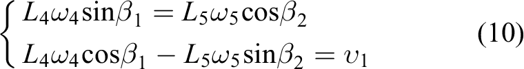
in which ω 4 and ω 5 are angular velocities of rod C1B1 and rod A1B1. υ 1 is the speed of the electric push rod. m is the vertical distance between the electric push rod and point O1, taking a value of 25 mm in such an instance. s represents the horizontal distance from the electric push rod to point O1, determining a result of 33 mm. The stroke of electric push rod (h 1) is ranged from 0 mm to 20 mm, and its speed is limited to 4 mm/s. Finally combining relationships between the flipping angle β 1 and time t, the maximum flipping angle is defined as 36°.
The cutting mechanism can be simplified as a slider mechanism with a planar guide rail, and its structural diagram is also shown in Figure 8. Specifically, R is the length of crank A2B2 of the offset crank slider mechanism, and L is the length of connecting rod B2C2. e is the eccentricity. ϕ 1 and ϕ 2 are the crank and connecting angles, respectively. Therefore, the displacement of the blade can be given by 34

The speed and acceleration of the blade will be characterized by equations (12) and (13) individually 34


where ω 6 is the angular velocity of the crank. It is also concluded from above three expressions that the displacement, velocity, and acceleration can be characterized as functions of the rotation speed of the crank. 35
Behaviors drawn from the ADAMS model and comparison with mathematical models
In the ADAMS platform, the centroid of the lead screw (scruw.cm) is defined as the origin of the entire simulation model, as shown as Figure 9. The simulation duration is taken as a picking cycle of the end effector. For an instance, times for the grabbing, flipping–cutting, maintaining the flipping and cutting state, resetting after the flipping–cutting, and unloading actions are assumed to be 3s, 5s, 2s, 3s and 2s, and the total time is close to 15s. The step time for simulation is selected as 0.03s. On the basis of definitions of parameters, the dynamic process can be presented by Figure 10. The displacement, angle, velocity, and acceleration features can be exported in the postprocessing module (Postprocessor). As is shown in Figure 10, almost all actions of this effector have been simulated effectively without any motion interference, which is highly consistent with requirements of structural schemes and the working principle.

The ADAMS model.
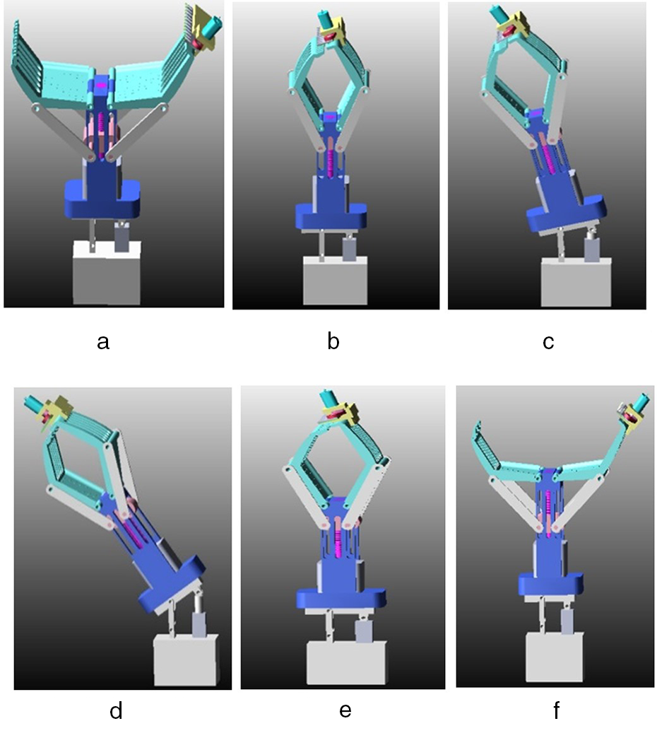
Simulation for picking process: (a) initial stage; (b) clamping; (c) flipping–cutting; (d) limit position; (e) returning; and (f) opening.
The displacement behavior of the V-shaped finger can be explained by Figure 11, and its velocity and acceleration in the X-axis direction will be presented in Figure 12. Evidently, the maximum grabbing range is about 180 mm. The V-finger stops moving if the screw nut is reached to the maximum stroke. The minimum range for grabbing is only 7 mm that is closed to that of mathematical models. During the clamping process, the maximum speed and acceleration of this V-shaped finger are 90 mm/s and 185 mm/s2. The curves of speed and acceleration are relatively smooth without significant instantaneous impacts. The clamping mechanism should be operated without the interference.

The displacement of V-shaped fingers.

The speed and acceleration of V-shaped fingers in the X-axis direction.
Demonstrated in Figure 13, the displacement of the centroid of the upper blade in the cutting mechanism is varied from 0 mm to 12 mm, thus generating a stroke of 12 mm. Such a stroke is quite consistent with requirements of structural design. In Figure 14, the speed of the upper blade is ranged from −180 mm/s to 157 mm/s, and the acceleration range is varied from −3567 mm/s2 to 5700 mm/s2. The speed and acceleration curves are also smooth without significant instantaneous impact. The peak–valley and peak–peak positions of the displacement curve appear if the speed of the upper blade is zero. The slope of speed rise is greater than that of reduction, and rise speed is faster than the descent one. Those behaviors are produced by quick return motion characteristics of the offset crank slider mechanism.

The displacement of the upper blade in the Z-axis direction.

The speed and acceleration of the upper blade in the Z-axis direction.
To validate the feasibility of two simulation models, three important parameters such as θ 1, θ 3 and β 1 are selected to evaluate them. As shown in Figure 15, θ 1 from mathematical models is changed from 32° to 90°, and another one ranged from 35° to 90° is obtained by the ADAMS model. Therefore, the variable behavior of θ 1 concluded from two models is quite consistent with each other, and the maximum absolute error is about 4°. For θ 3 in the clamping mechanism, the result of the mathematical model is ranged from 26° to 43°, and it is varied from 23° to 46° in view of ADAMS simulation. The maximum absolute error is 3°, as presented in Figure 16. The consistency of two type of results for flipping angle β 1 is also achieved with a maximum absolute error of 2°, demonstrating as a range from 0° to 36° and another one from 0° to 34° in Figure 17. All of relative errors of three parameters are less than 10%. Therefore, the proposed scheme of this end effector is feasible from a theoretical perspective, and two types of models are also reliable.

Comparison for θ 1 of the clamping mechanism in view of two models.

Comparison for θ 3 of the clamping mechanism in view of two models.

Comparison for flipping angle β 1 in view of two models.
Validation for the feasibility of the scheme in a lab
To evaluate the rationality of the structure, the expected action for picking fruits, working durations, and so on, a simple test bench is established for picking apples, citrus, and kiwifruit in a lab, as shown in Figure 18. The main work of this study is to determine whether the excellent performance of this end effector could be achieved or not, and the visual system has not been considered. It is assumed that the orientation information of the target fruit is known. Therefore, the center point and stem of a fruit are arranged in the same plane that is also the center plane of the claw. Essentially, such a plane is the central symmetry plane of two V-shaped fingers.

The experimental platform in a lab: C: cutting mechanism; 1: infrared switch sensors; 2: V-shaped fingers; 3: connecting rods; 4: stepping motor; 5: electric push rod; 6: base; 7: governor; 8: microcontroller; 9: pressure sensor; 10: screw nut mechanism; 11: racks; 12: I-frame; 13: driver for stepping motor; 14: 24 V power supply.
On the basis of such a bench, the end effector will be fixed on the test bench, and it is controlled by the upper computer software for continuous picking action, such as grabbing, flipping–cutting, returning, and unloading behaviors. Parameters including the speed of the stepping motor, the clamping force, the stroke of electric push rod, and the flipping angle can be reasonably defined in the central control program. In experiment, the position information of a spherical fruit obtained from the infrared switch sensor will be transmitted to the microcontroller.
The microcontroller will further send a signal to the driver of the stepping motor. The V-shaped fingers will be driven by the movement of the stepping motor, thus achieving a suitable speed of the V-shaped fingers and clamping fruits, such as 10 mm/s. The clamping action should be stopped if the clamping force reaches the preset value of 15 N that is detected by the pressure sensor.
The micromotor starts to work, further driving the blade to perform reciprocating cutting motion. At the same time, the flipping baffle will be rotated by the driving movement of the electric push rod in view of 4 mm/s. The picking action will be stopped as long as the flipping angle has been reached to the set value. Each mechanism will be then reset in sequence to complete fruit unloading. The picking process is shown in Figures 19 to 21, which is basically consistent with the action from ADAMS simulation, such as approaching the fruit, grabbing the fruit, flipping and cutting stems, resetting mechanisms, and unloading the fruit.

The picking process for oranges: (a) initial position; (b) clamp fruit; (c) start to flip; (d) complete cutting; (e) reset; and (f) unload.

The picking process for apples: (a) initial position; (b) clamp fruit; (c) start to flip; (d) complete cutting; (e) reset; and (f) unload.

The picking process for Kiwi: (a) initial position; (b) clamp fruit; (c) start to flip; (d) complete cutting; (e) reset; and (f) unload.
Partial indexes of experimental results.

The experiment for three groups had been completed, and the number of different types is the same (same number of sample). Finally, the number of successful grabbing, number of successful flipping–cutting, success rate of picking, average picking time, and damage rate are worked as indexes of evaluation, as shown in Table 1.
Evidently, almost all of fruits could be grabbed successfully, thus achieving a success rate of 100%. The success rate of picking completely exceeds 80%. The end effector itself has a good harvesting effect. The shortest average picking time is 9.6s, and the damage rate is 0. Therefore, it is potential that the picking efficiency can be improved on the basis of a lower rate of damage. The failure of spherical fruit picking in the experiment would be concentrated on two aspects. For example, the hardness at the fork of stems of citrus is relatively high, and it is difficult to cut off. During the flipping and cutting process, the sliding action between the V-shaped fingers and some kiwifruit occurs, further resulting in the failure to smoothly flip and cut the stem.
Conclusions
Combining the clamping, flipping, and cutting functions, the end effector with two V-shaped fingers and the flipping–cutting mechanism is designed, simulated, and tested for obtaining suitable performance of itself. The main functions of it could be achieved by following factors. Adopting a clamping mechanism with the screw nut, the grabbing range of the clamping mechanism can be adjusted through the stroke of the screw nut. In the flipping mechanism, the flipping angle of the flipping mechanism is controlled by the stroke of the electric push rod. For the cutting mechanism, the reciprocating cutting mechanism with two blades presents advantages such as fast cutting speed, low power, and low vibration. The separation method fusing characteristics of flexible-flipping and cutting actions can be effectively achieved by the combination of the clamping mechanism, flipping mechanism, and cutting mechanism. The picking efficiency and improvement of universality for diverse fruits can be also ensured by continuously picking motion and the control process, such as grabbing, flipping–cutting, resetting, and unloading actions. For apples, oranges, and kiwifruit, the success rate of fruit picking exceeds 80%, and the average picking time for a single fruit can be reduced to 9.6s with a damage rate of 0. Working strokes, speeds, accelerations, and crucial moving angles for main components in clamping, flipping, and cutting mechanisms are consistent with each other in view of mathematical models and the ADAMS model. The scheme and simulated models are feasible.
It is concluded from above main issues that such a structure with a combination of flipping and cutting functions is potential to pick diverse types of spherical fruits, thus presenting a good universality. The excellent performance after further optimization, control, visual system, and mobile platform could be anticipated in future.
Footnotes
Declaration of conflicting interests
The authors declared no potential conflicts of interest with respect to the research, authorship, and/or publication of this article.
Funding
The authors disclosed receipt of the following financial support for the research, authorship, and/or publication of this article: The work described here was financially supported by Natural Science Foundation of Hubei Province (No. 2021CFB592)