
Abstract
Conventional grippers are designed for specific applications. They often encounter difficulties when grasping different objects in unstructured environments. This article introduces a novel gripper to challenge the universal grasp capability. Passively slidable pins are array arranged in the gripper. By meshing of pin’s elliptical contour, shape adaption to various objects is achieved in both vertical and horizontal directions using a single motor. Contact force is analyzed based on static and kinetic friction. Kinematic simulation on the grasping process reveals the interaction between critical parameters and the overall grasp performance. To conclude, a prototype pin array gripper demonstrates high adaptability to various objects in real-world testing.
Introduction
Grippers have been widely used in robotic part handling and assembly, which range from simple industrial grippers to multifingered robot hands. Both the flexibility of production lines and the complex tasks of advanced robots 1 require a more versatile gripper. Over decades, not satisfied with industrial grippers, researchers have been proposing new grippers to grasp various objects autonomously, that is, the universal grasp capability. One direction is to exploit the model of human hands, making use of the dexterity of our daily grasp. The other direction is to build unarticulated universal grippers, which go beyond the grasp capability of human hands.
Industrial grippers are generally simple-structure, highly customized for repetitive tasks. They are built on specific physical effect to perform usually a single task. For example, a magnetic gripper is effective for manipulating ferromagnetic materials with plain surface; a cryo gripper 2 is suitable for handling textiles and fiber compound plastics. The most popular one is the mechanical gripper. It has two or three jaws which either pivot or remain parallel during open/close motions. 3 It is clear that they can only grasp a few types of objects, therefore, are limited for future applications where universal grasp capability is needed.
Multifingered robot hands have been developed to achieve sufficient dexterity by programmable flexibility. They usually have three or more articulated fingers like humans. Thanks to their anthropomorphic design, they are potentially capable of grasping as real hands. Many researches focus on the realization of the six generic grasp modes, 4 which realize 80% of our daily grasp. Dexterous hands with full-actuated fingers were developed since the 1970s. 5 Since all joints are independently actuated, the dexterous hand is in fact a redundant robot system, which leads to high control complexity and inverse problems. 6 For example, great efforts were made on the Shadow Hand 7 with 20 degrees of freedom (DOFs). For this reason, grasping and dexterous manipulation rank among the principal challenges in robotics. A trade-off between the universal grasping and control complexity is underactuated robot hand. 8 By implementing compliant joints, underactuated robot hands possess more DOFs than number of actuators. 9,10 First introduced by Laval University, 11 more underactuated robot hands were designed and a few were commercialized 10 because of their high adaptability to different scenarios and low control complexity. However, the inherent limitation is loss of dexterity, sometimes ejection of objects, 8 due to less actuators and passive elements.
Universal grippers can grasp a wide variety of arbitrarily shaped objects, specifically target the universal grasp capability. They are often unarticulated and highly compliant, which do not require posture estimation of the target object or complicated grasp planning. 12 Amend et al. have proposed a jamming gripper, 13 in which ground coffee is wrapped by elastic membrane in a ball shape. It is soft while adapting to the shape of object, then vacuum hardens to grip objects securely. Okatani et al. have also implemented the same principle for their grippers, with a further attempt on magnetorheological (MR) fluid. 14 The MR fluid solidifies when subjected to magnetic field, which is an alternative to vacuum jamming of granular materials. Inspired by the form fit of the chameleon’s tongue, FESTO company has presented the flex shape gripper. 15 It consists of a water-filled silicone membrane with a sucker at its front and pneumatic piston with springs, which wraps itself around grasped items in a flexible manner. Soft fingers are promising in many aspects. 16 –19 Actuated by air pressure or shape memory alloy, soft fingers can easily adapt to the contour of objects. Some researchers integrate the universal grasping mechanisms into an articulated rigid finger, 20,21 making it even more versatile. Inspired from gecko adhesive, S2DM gripper 22 was developed to grasp using only shear force. Petterson et al. have proposed a three-dimensional (3-D) Bernoulli gripper. 23 It combines Bernoulli principle and a pin locking mechanism to achieve 3-D grasping. Most of these grippers implement soft materials for shape adaptation. However, it potentially limits their life span due to frequent deformation of materials. Moreover, due to the soft contact, their grasp force and placement precision are limited.
In order to keep the contacts rigid while retaining shape adaptation, the pin array grippers are proposed. NASA has developed the microspine gripper. 24,25 It utilizes a hierarchical, radially symmetric array of claws with suspension flexures, to perform omnidirectional gripping. Wang et al. have proposed a linearly constrained microspine array mechanism, 26 which is capable of overcoming strong shear forces on rough terrain under an appropriate normal force. However, they can only be applied on porous surface structures. Scott has introduced the Omnigripper, 27 where two ranks of pins could passively slide up and down to conform to the shape of a target object, before pinching it from two sides. However, it is in fact a two-jaw gripper, which requires the target object located between the two ranks of pins. Rather than pinching from two sides, the cluster tube universal gripper 28 developed by Fu et al. bundles up pins by three flexible cables in a convergent manner. However, since all the pins swing to the center, its grasp force decreases significantly if the target object does not locate at the center of the pin array. Besides, the cable route does not allow for high pin density design, which limits the adaptability of the gripper. Table 1 shows the differences between the abovementioned universal grippers, including the pin array gripper proposed in this article. They are realized by various physical effects, which make them special and universal.
Comparison of universal grippers.

MR: magnetorheological.
In this article, we introduce a novel universal gripper based on meshed pin array. It provides a better solution to couple all pins to build multipoint contacts with objects over our preliminary research reported by Mo and Zhang, 32 together with other possible meshed pin array configurations, kinematic simulation, and experimental verification. This article is organized as follows. The second section demonstrates the inspiration, working principle, and mechanical design of the gripper. The third section analyzes the contact model and verifies the universal grasp capability through kinematic simulation. The fourth section shows the effectiveness of the prototype, illustrated by grasping of various objects.
Pin array gripper design
To achieve the universal grasp capability, a gripper needs to adapt itself to the shape of the target object. Pin array shows high adaptability evidenced by several commercial products and research attempts. As shown in Figure 1, pin art (pinscreen) is a boxed surface made of a crowded array of pins that are free to slide in and out independently in a screen to create a three-dimensional relief. It is a popular executive toy patented in 1987 by Ward Fleming. 33 A similar idea is the universal socket, 34 a single tool for different kinds of fasteners by using a bundle of retractable pins constrained by its housing. Not by passively adapting to the shape of objects, the other way is to actively actuate the pin array to build the desired 3-D/2.5-D tangible surface and provide haptics information, for example, Digital Clay 35 and Materiable. 36 In either way, pin array demonstrates high adaptability and potential for grasping, if each contacted pin is considered as a small jaw.

Adaptability of pin array products. (a) Pin art. (b) Universal socket.
Structure and grasp principle
The proposed pin array gripper composes of two parts: pin array and driving mechanism, as shown in Figure 2. The pins can slide along their axes and are biased by spring force away from a frame onto which the pins are slidably held. They are arranged in a matrix form, close to each other. More importantly, pins are coupled by a driving mechanism above, which drives all the pins toward a target item.
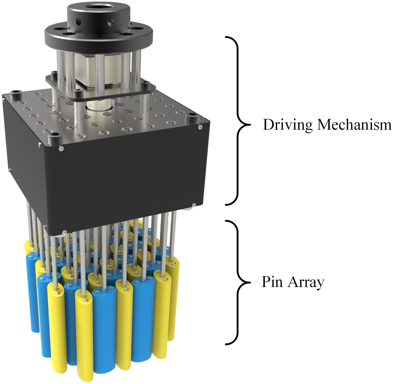
Structure of pin array gripper.
The sliding and coupled movement achieve shape adaption in two dimensions: vertical and horizontal. When the gripper is forced over an object, a group of pins are pushed up, adapting to the surface of the object vertically. The pins not being pushed will match the contour of the object, if pins are crowded enough, so that shape adaption in horizontal direction is accomplished. Figure 3 presents the basic grasp process of adapting and grasping a sphere object.

Schematic of grasp sequence. (a) Approaching; (b) adaption; (c) grasp; and (d) lift.
Approaching
The pin array gripper approaches an object along the pin axis.
Adaption
When contacted with the object, a pin slides upward passively, with respect to the frame. When not contacted, a pin remains in full length. In this way, the object is covered by the pin array, subjected to its shape.
Grasp
After the object is fully covered, the driving mechanism starts to drive the pins toward the object horizontally. Each pin along the side of the object functions as one jaw to clamp the object. The retention force is generated via force-closure between the pins and the object.
Lift
The pin array gripper lifts the object for further manipulation.
As for releasing, the sequence is reverse.
Pin design
To achieve the described adaption and grasping, each pin should be able to move in two directions, that is, passive sliding along its axis and displacement in all lateral directions. The sliding motion can be easily realized by a spring-loaded piston, as shown in Figure 7. The piston rod is relatively fixed and connected to the driving mechanisms, while the cylinder is the pin that slides passively.
However, it is not that straightforward to establish the lateral contacts between pins and objects. Pins should be crowded enough for shape adaption, but with a gap in between reserved for lateral displacement. The lateral displacement needs to be in all directions so that objects not in the center or in irregular shape can be grasped. Interference between pins should not occur. In addition, it is not feasible to drive each pin independently with independent actuator, since pins are small and should be as many as possible. The key is to find a way to drive all the pins translate simultaneously, to detect and contact with the target items. Hence, a novel pin design is proposed.
The pin section is not circular, but elliptical, as shown in Figure 4. The inspiration is from the cam mechanism and oval gear. When a cam pushes a follower, looking from its rotational axis, the push motion is actually accomplished through the lateral contact. A rotating pin with cam contour can also push an object, thus establishing a lateral contact. If pins are too close, they are likely to block each other, whereas smaller spacing suggests better shape adaption and more contacts. The solution for this conflict is the oval gear meshing. Paired oval gears are right next to each other, with least spacing in between. Therefore, pins with elliptical section can also pair with adjacent pins. The rotation of a pin in angle φ will introduce a translational displacement s, which can be obtained through solving extrema of ellipse from parametric form

Setting s’ = 0 yields

where a is semi-major axis and b is semi-minor axis. In Figure 4, the yellow ring indicates a possible contact zone, through which the pin will sweep. In this way, the lateral displacement of a single pin in all direction is achieved.

Two adjacent pins, seeing from axial direction.
With this elliptical pin section design, less spacing and omnidirectional lateral motion lead to better shape adaption. The configuration of pin array is shown in Figure 5(a). Each pin is surrounded by four pins. Every two adjacent pins rotate in opposite direction with an initial phase difference of 90°, as oval gear pair. In the drawings, the red pins rotate clockwise, while the light blue pins counterclockwise.

Possible pin array configurations.
In fact, the pin section does not necessarily to be elliptical. It should be centrosymmetric and possible for meshing. Other possible pin sections and corresponding pin array configurations are shown in Figure 5(b) and (c). The yellow rings represent the possible contact zones, while the white voids are noncontact zones where no pin can reach. We assume that, if the contour of a target object crosses enough number of contact zones, established lateral contacts will provide sufficient grasp force to balance external force on the object through friction. To increase the chances of lateral contacts, the ratio of contact zones and noncontact zones should be as high as possible. Therefore, the elliptical section configuration shown in Figure 5(a) is favored for further investigation in this research.
Driving mechanism
The driving mechanism is to generate the expected rotation of the pins and provide the grasping force against external force. It is subject to the pin configuration. In this research, a driving mechanism for the pin array shown in Figure 5(a) is introduced.
Based on the rotation direction, the pins can be divided into two sets. Since the rotation of each pin set is synchronized and symmetric, the rotating motion can be transmitted to each pin via identical or symmetric intermediate components. Ideally, the driving mechanism could be a matrix of oval gear pairs. It should provide perfect velocity profile for the meshing motion between pins. However, the high cost of oval gears does not justify the design.
A matrix of standard gears will also work. When two adjacent pins rotate at the same constant speed oppositely, start from the position shown in Figure 4, the largest distance between their surfaces can be found in Figure 6. The semi-major axis a is set to be 10 mm, while semi-minor axis b iterates from 5 mm to 9 mm. The results show that the largest spacing Δ is less than (a - b)/2, and no interference occurs. Since the dimension of pins should be even smaller, this spacing is negligible.

Distance between adjacent pins while rotating.
The driving mechanism is presented in Figure 7. A single motor with reducer is located in the center, connecting to a piston rod via a coupling. A driving gear is mounted on the piston rod, which transmits the torque to other gears in the array. The lower end of a piston rod is connected to a piston, whose section is hexagon, corresponding to the chamber inside the pin. So that the rotation motion can be transferred to the pins. Note that the connection between piston and rod is not rigid but flexible. When one pin is contacted with objects, the other pins can rotate slightly further to build more contacts. This is important to prevent blocking of pins before the target object is grasped. This driving mechanism applies only one actuator to drive multiple pins, which means the gripper is underactuated. With this simple and robust design, the gear transmission is more reliable and easier to implement than the previous attempt of parallelogram mechanism by Mo and Zhang, 32 of which two frames interfere sometimes. The pin array can be built in large matrix with small pins inside.

Transmission of pin array gripper.
Grasp analysis
To study the universal grasp capability of the proposed pin array gripper, it is important to analyze how the lateral contacts are built, which eventually leading to normal forces and friction on objects for grasping. In this section, analytical approach is applied to investigate the contact of a single pin. Simulation method is implemented to study the interaction between the pin array and the target objects.
Contact model
In order to understand how the geometry of a pin influence the grasp performance, a contact model based on static friction and kinetic friction is proposed. As shown in Figure 8, a pin is driven by torque T, rotates clockwise, and touches an object. The distance between the contact point and the pin center is re , with a rotation angle Θ to the major axis. The linear velocity of pin contour at the contact point is ve , which is perpendicular to re . The vertical dash line is tangent to the surface of both pin and object, where ϐ is the angular difference to ve . The resultant force acting on the=object is Fc , where r is its arm to the pin center. It can be decomposed into normal force FN and friction force Ff .

Lateral contact model.
Let μs and μk be the coefficient of static friction and kinetic friction, respectively. i labels the torque applied on the ith pin of static friction, while j the torque applied on the jth pin of kinetic friction. The corresponding grasp force Fgs and Fgk for static friction and kinetic friction situation are given by


Equations (3) and (4) indicate that it is possible to increase the grasp force in three ways: using proper material with high coefficient of friction, increasing input torque, and enlarging the size of pins. Details on the contact model are described by Mo and Zhang. 32
A single pin does not grasp an object, while multiple contacts around the object do. Assuming there exists both static and kinetic friction contacts. The total grasp force FG is given

where the number of static and kinetic contacts are m and n, respectively. i and j label each specific contact. For example, given the boundary conditions shown below: contacted pin torque: Ti = Tj = 10 Nmm, semi-major axis: a = 10 mm, pin eccentricity: e = 0.75, coefficient of friction: μs = μk
= 0.5, number of contacted pins: n = m = 5, and rotation angle Θ: evenly distributes from 0° to 90°.
The grasp force can be up to 212 N in this model.
Kinematic simulation
Modeling on only a single pin does not reveal the general contact situation of the whole pin array. Although the grasp force can be formulated analytically, the needed boundary conditions are not always available, especially the exact location of contact. Universal grasp capability suggests that the shape, position, and orientation of the target object are all arbitrary. During the grasp process, the object might probably deviate a little from its original pose, making it even harder to predict the specific locations of the contact points. A complex sensory system to determine every contact location is not practical. Thus, a simulation model is proposed to demonstrate the general contact situation, taking into account the randomness of shape and pose of the target objects.
The model simulates the shape adaption process kinematically. Looking from the axial direction of pins, the simulation is in two-dimensional, showing the top view of an object grasped by an array of ellipses. Pins and objects are regarded as rigid bodies. As shown in Figure 9, each grasp in the simulation composes of three steps.

Shape adaption process in simulation. (a) Pin array generation; (b) pin slidin; and (c) rotation and contact.
Pin array generation
Given a specified geometry of the pin contour and number of pins, a matrix of n × n pins is generated. The blue pins rotate clockwise, while the yellow pins counterclockwise.
Pin sliding
The contour of a target object is imported. It is placed near the center of the pin array. Pins within or in touch with the object contour are removed, which means they slide passively and do not contribute to the lateral contacts. It is corresponding to the adaption process, as shown in Figure 3(b).
Rotation and contact
The rest pins rotate iteratively at a specified step, for example, 2° per step. After each rotation step, collision between the pins and the object is checked and recorded. If collision occurs, the object will be pushed by the contacted pins. For each contact, on the one hand, the object translates a penalty distance away from the contact point. This penalty distance is in proportional to the depth the pin penetrates in the object and reduced by a factor of 0.8 to reveal the flexible connection between piston and piston rod. On the other hand, the object rotates oppositely to the rotational direction of the contacted pin and reduced by a factor of 0.5 for the consideration of both rolling friction and dry friction. The rotation ends at 90°, since after that the pin array motion will be another similar cycle. This is corresponding to the grasp process, as shown in Figure 3(c).
In reality, the rotation ends earlier before it reaches 90°, because the cumulating contacts block the rotation earlier. At the block moment, the object is grasped at peak grasp force, therefore, the best grasp situation. However, since the object is manipulated during each step, which is strongly influenced by its initial position and orientation, it is not easy to predict when the block occurs. We use the recorded number of contacts at each step to benchmark how well the object is grasped. It is assumed that the more contacts, the better the grasp performance, which means the grasp is more stable. Thus, the maximum number of contacts during each grasp indicates the best grasp situation. If the pins are small and crowded enough, the manipulation before the object is securely grasped will be small and negligible.
To make the simulation closer to reality, the object contours in the simulation are extracted from real world, as shown in Figure 10. They are different in shape and size, and are irregular, in order to validate the universal grasp capability.

Objects used in the simulation.
By testing different pin array designs based on this simulation model, their influence on the universal grasp performance is revealed. In testing, the maximum number of contacts is not directly obtained from one grasp but from an average of 28 grasps. Each pin array design will be applied for grasping of seven different objects. For each object, grasping is repeated for four times, where the position and orientation of the target object is random. In this way, by 28 iterations on different objects of different poses, the average maximum number of contacts is more reliable to benchmark the specific pin array design. The simulation results are shown in Figure 11, where the blue lines are polynomial fitting of the data.

Influence of different designs on the universal grasp performance.
Rotation stroke is a predefined pin rotation end point. By testing different rotation strokes, how contacts develop during continuous rotating is shown. The pin array contains 30 × 30 pins, with eccentricity of 0.78. The rotation stroke ranges from 5° to 90° is studied. As shown in Figure 11(a), the average maximum contacts increase as pins rotate. It can be understood as more and more pins penetrate into the object, so that more contacts appear. The grasp force will keep increasing during actuating, which is good for grasp force control.
Number of pins at each edge indicates the density of pin array. The pin array is generated at a scale around 120 × 120 mm2. The more pins, the smaller the dimension of each pin. The eccentricity is set as 0.78, and the rotation stroke is 90°. Testing of pin array from 6 × 6 to 30 × 30 is conducted. As shown in Figure 11(b), the assumption “more pins, more contacts” is validated. The increase of contact is almost linear with respect to the number of pins at each line, which is the square root of total pin number. Therefore, it is not advised to build a huge matrix of pins in a same space, since the performance increases slowly, and the grasp force will be reduced as presented in “Contact model” section.
Eccentricity is a critical parameter for the pin design. In an array of 30 × 30 pins, the rotation stroke is set as 90°. We study the eccentricity of pin contour from 0.5 to 0.9, with a step of 0.02, because the eccentricity beyond this range makes a pin either too close to a circle or too flat. The results in Figure 11(c) indicate that a thinner ellipse contour performs better than a rounder one. It is reasonable since the possible contact zone of a thinner ellipse is larger.
From the simulation results, the universal grasp capability is basically realized. The grasp performance can be improved in three ways: driving pins rotate further, increasing the number of pins, and designing pin’s contour with larger eccentricity. Note that they may be in conflict with some physical conditions. More pins in the array require better manufacturing and more assembly efforts. Larger eccentricity of pin contour might lower the mechanical strength of the pin.
Experiments
A prototype gripper was built to validate the proposed design and test the predicted performance. As shown in Figure 12, the gripper consists of 45 pins with elliptical section. Pins are arranged in a 7 × 7 matrix where the four pins at the corner are removed. The overall scale of the pin array is around 120 × 120 mm2, which is corresponding to the simulation setup. The slide stroke of each pin is 65 mm, constrained by a spring inside. The semi-major axis and semi-minor axis are 10.5 and 6.5 mm, respectively, where the eccentricity is 0.78. The pin body is 3-D printed with stereolithography, in order to reduce weight with good surface quality. The piston and pin rod are made of aluminum, because their rigidity is essential to keep the pins from bending while grasping. Located in a 3-D printed housing, the driving mechanism includes a set of meshed spur gears, whose module is 0.8 and number of teeth is 22. Note that the number of teeth is not arbitrary. Because the initial phase difference of adjacent pins is 90°, and each pin is meshed with four pins in a symmetric form, the number of teeth must be in the form of 4n + 2, where n is an integer. A DC motor (JSX 950-370) with reducer is fixed over the driving mechanism, providing the needed power for adaptive grasping. On the top, a connector makes it possible to be mounted on an industrial robot. Table 2 presents the specifications of the proposed pin array gripper. Sensory system is not yet implemented in this prototype, since it is only used to verify the mechanical properties.

Pin array gripper prototype.
Pin array gripper specifications.

Grasp experiments were conducted to test the universal grasp capability. Objects with irregular shape were selected for testing. Bottom views of the gripper before and after grasping are illustrated in Figure 13. It shows high adaptability to different objects. With limited number of pins, objects can still be well adapted. More importantly, no computation effort is needed to plan the optimal grasp points. The gripper is simply placed on the target object, without knowing the precise shape or position of the object. It is one of the key improvements over the prior pin array grippers. For example, the Omnigripper 27 requires that the target object located between the two ranks of pins while the cluster–tube universal gripper 28 requires the object placed at the center. The proposed elliptical pin can provide contact force at any direction, thus not discriminative to the position of objects. It can be assumed that with more pins, the gripper is potentially capable of grasping multiple objects at once. One issue occurred in this prototype. The bottom left picture of Figure 13 shows the grasping of a ball. The pin array is a bit out of shape, which is not expected. This is a result of the bending of the pin structure. The aluminous piston rod is rigid enough, whereas the frame was not able to fix the piston rod securely. Thus, the pin structure deviated, as if pivoting on the frame. The connection of pin rod to the upper and lower frame should be reinforced with higher machining accuracy in the future version of prototype to increase its rigidity.
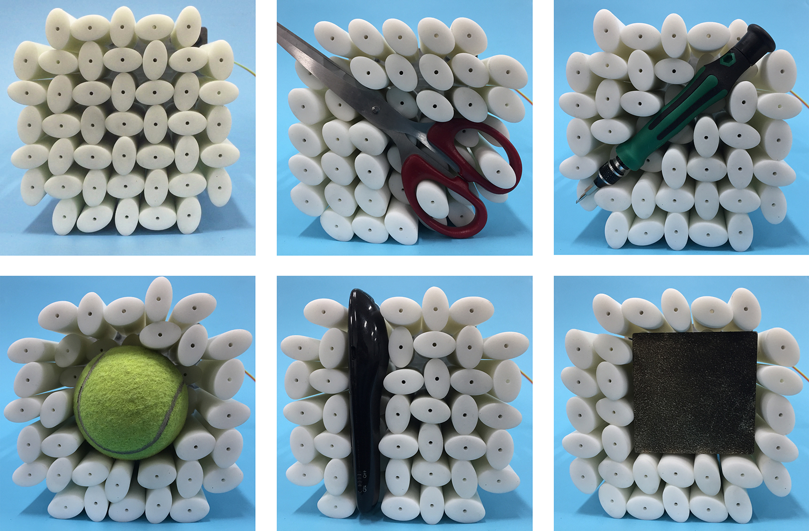
Grasp experiments on different objects.
In addition to the universal grasp capability, grasping force is tested to examine how different objects influence on the grasp performance; 44 boxes (polylactic acid (PLA), 3-D printed) are selected for testing, whose lengths range from 20 mm to 100 mm, widths range from 20 mm to 90 mm, and heights of 20 mm. Each box is tested for three times at different grasp positions. For each test, the test object is connected to a push gauge (elecall NK-500 model) through a thin cable. When the object is securely grasped, the number of lateral contacts is recorded. Then, external force along the pin axial direction is applied on the push gauge to drag the object away from the gripper until the object separating from the gripper. The maximum grasp force is measured. Since the selected spring in each pin is quite weak, the ejection force applied on the object is negligible.
Figure 14 shows the average grasping force of the objects of different dimensions. Generally, the larger the test object is, the higher the grasping force is. Since larger object is likely to establish more lateral contacts with pins, the grasping force is therefore higher. Note that the grasping force for objects of width of 60 mm is even higher than the objects of width of 70 mm. We found that the number of lateral contacts of the 60 mm objects is in fact higher. It could be the result of low pin array density where the objects of width of 60 mm accidently match the spacing between several pins. Among these 132 tests, the relationship between number of lateral contacts and grasp force is illustrated in Figure 15 with error bars. The average number of contacts is found to be 4.37 for this 7 × 7 pin array setup. The grasping force increases with a greater number of lateral contacts. The assumption “the more contacts, the better the grasp performance” proposed in “Kinematic simulation” section is validated.
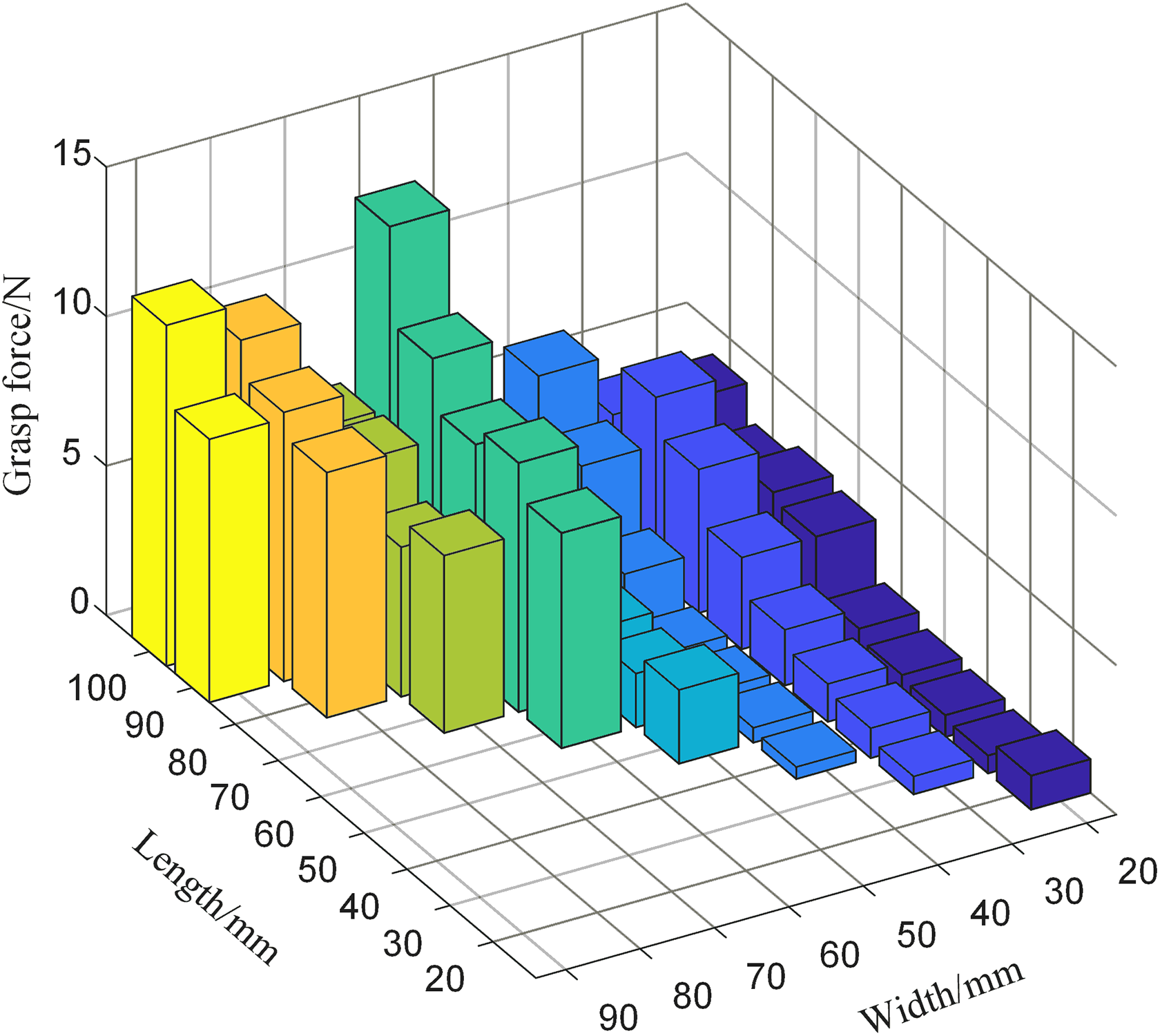
Grasp force distribution of different objects.

Influence of lateral contacts on grasp force.
The grasp experiments show that the maximum weight that can be grasped is around 1 kg. The displacement deviation introduced by the rotating pins is around 2 mm. A video of the conducted experiments is provided with the “accompanied_video.”
Conclusion
This article has presented a novel pin array gripper that challenges the universal grasp capability. With this gripper, objects of different shape, size, and pose can be grasped. This versatility may make the gripper suitable for unstructured environments in many flexible production lines, such as sorting and assembling.
It is the special pin array design that enables the universal grasping. Slidable pins with non-circle section are arranged in a matrix form. The adjacent pins are “meshed” as gear pair, rotating at opposite direction. Therefore, lateral contacts with objects can be established in all directions. Particular attention was given to study the instance of elliptical contour pin. Contact model on single pin considering static and kinetic friction was developed to estimate the grasp force. To reveal the general contact situation, kinematic simulation on the shape adaption process of the complete pin array was carried out. The influence of rotation stroke, number of pins, and eccentricity was investigated, which showed possible improvement directions. A gripper prototype was built with 45 pins. Grasp experiments of the gripper have demonstrated high adaptability on various objects. The grasping force is higher for larger objects thanks to more lateral contacts.
Future work is planned for the study of force control and tactile display. An improved prototype with higher pin density will be developed to examine the impact of pin density. Sensory system will be integrated to provide haptics and force information.
Footnotes
Declaration of conflicting interests
The author(s) declared no potential conflicts of interest with respect to the research, authorship, and/or publication of this article.
Funding
The author(s) disclosed receipt of the following financial support for the research, authorship, and/or publication of this article: This research was supported by the National Natural Science Foundation of China (Grant No. 51575302), the Beijing Natural Science Foundation (Grant No. J170005), and the National Key R&D Program of China (Grant No. 2017YFE0113200).
Supplemental material
Supplemental material for this article is available online.
References
Supplementary Material
Please find the following supplemental material available below.
For Open Access articles published under a Creative Commons License, all supplemental material carries the same license as the article it is associated with.
For non-Open Access articles published, all supplemental material carries a non-exclusive license, and permission requests for re-use of supplemental material or any part of supplemental material shall be sent directly to the copyright owner as specified in the copyright notice associated with the article.