
Abstract
To solve some defects of exoskeleton robot at present, this article establishes the dynamic model of human lower limb. The torque curves for hip joint and knee joint are obtained. A dynamics simulation is conducted in ADAMS which will guide the selection of motors and reducers for exoskeleton joints. Three structural design projects for leg and an integrated joint with the function of force perception are proposed. Then a lightweight exoskeleton is put forward and a kinematics simulation of man–machine coupling system is carried out in ADAMS. This article sets up a 24-V low-voltage control electrical system and a rehabilitation training expert system. Some performance tests and clinical experiments are carried out by an experimental prototype. The results show that the joints have sufficient driving torque. Leg structure has large adjustment range and self-locking function. The exoskeleton has lightweight and does not interfere with human body during movement. The expert system has a friendly operation interface and abundant functions. Clinical experimental results show that lower limb exoskeleton has good rehabilitation effect for some diseases.
Keywords
Introduction
Exoskeleton is a kind of intelligent wearable device. It has a bionic structure which can keep consistent with the wearer’s limb movement. 1 Lower limb rehabilitation exoskeleton is an important application of exoskeleton in the medical field. It has been proved that exoskeleton has a good effect on the rehabilitation of lower limbs for stroke patients. 2 In recent years, many major breakthroughs on exoskeleton have been obtained. 3 –7
An exoskeleton driven by wire rope is proposed in 2019 8 which is used to assist people with hemiplegic. The wire rope driving mechanism can simplify exoskeleton structure and reduce the volume of the exoskeleton. However, protective mechanism for wire rope is not designed. When an instantaneous impact happens, wire rope is easy to break. It will bring a serious threat to users. In addition, the leg adjustment mechanism cannot be adjusted by hand without tools. In 2020, a hydraulically driven lower limb exoskeleton is proposed. The author made a detailed kinematic and dynamic analysis of the exoskeleton. 9,10 The joints of hydraulic exoskeleton have higher torque than joints of motor-driven exoskeleton. Although the author does theoretical analysis in detail, the article does not carry out structural design for legs and joints. There is also no experimental prototype to verify the correctness of the theoretical results by experimental methods. In the same year, a passive lower limb exoskeleton is proposed. This exoskeleton has hip joints and knee joints. 11 It is designed with built-in spring mechanisms for gravity compensation. Although the exoskeleton has a compact layout with small protrusion, the torque joint provided is not big enough. Adjustment for leg length is not convenient. Without ankle support, the weight of the whole exoskeleton will be carried by human body. In 2021, Cao proposes a lower limb exoskeleton with rigid and soft structure. 12 The rigid structure supports the weight while the soft rope is directly fixed to the thigh and directly drives it. It has good walking assistance performance with small size and lightweight. However, due to the use of wire rope drive, the safety of wire rope also needs to be considered. At the same time, exoskeleton joints do not have force perception function. The adjustment mechanism still needs to be improved. Also in 2021, a lower limb exoskeleton with bioinspired knee joint is proposed. 13 Unlike other exoskeletons which simplify knee joint into a revolute pair, researchers have carried out a detailed bionic design for knee joint. Both curved guide rails and bearings are used to design knee joint avoiding misalignment. Although the working path of the knee joint is very similar to that of human knee joint, the structure is very complex. It is far from practical application. It is still in the stage of laboratory research. The above research studies are focused on the structure design and analysis of exoskeleton. None of them mentions the development of rehabilitation training expert system. There are some other achievements in exoskeleton. 14 –18 These will help to obtain better prediction for human movement intention. They can improve the comfortable feeling.
Based on the previous theoretical research, some technologies have been transformed into commercial exoskeleton products. ReWalk exoskeleton was proposed in 2006. It can help paralyzed patients stand-up again and walk autonomously. 19 In 2008, Hybrid Assistive Limb (HAL) was launched by Cyberdyne corporation in Japan. In 2013, it became the world’s first exoskeleton product with safety certification (ISO/DIS 13482). 20 Another representative commercial exoskeleton is Ekso. It was launched by Ekso Bionics in 2012 in USA, which uses aluminum alloy, titanium alloy, carbon fiber, and composite materials. There are 4 electric motors, 1 CPU, and 15 sensors for motion control and motion prediction. 21 Besides the products above, there are also some other exoskeletons. 22,23 These products all realized the function of walking assistance. However, there is still much room for improvement on lightweight structure, long endurance capability, development of expert system for rehabilitation training, accuracy control, selling price, and so on. 24,25
In conclusion, some problems existing in the current exoskeleton research studies and products are: (1) Some structures are complex which leads to high weight and large volume. When the battery capacity is certain and the battery cannot be replaced, it seriously affects the working time of exoskeleton. The operation of the leg adjustment is complex. It cannot realize the function of adjusting by hand without any tools; (2) Exoskeleton joint integration is not high. Joints do not have force perception function; (3) The interface of control system is not friendly enough for nonprofessionals to use. The control software is not developed for rehabilitation training, which can help doctors set parameters with shorter time and record training information. This article will focus on these problems.
Modeling and simulation
Before structure design, it is necessary to analyze physiological structure and motion principle of human lower limbs in detail. It will guide structure design and selection of motors and reducers.
Dynamic model and solution
There are three main joints on human lower limb: hip joint, knee joint, and ankle joint. Hip joint has three degrees of freedom, which can provide torque for the thigh. Ankle joint has three degrees of freedom, which can provide torque to foot. For knee joint, it has a complex structure. 13 In this article, it is simplified to a joint with one degree as another research. 26 The simplified joints are shown in Figure 1.

Structure simplification of human lower limb joints.
Based on Figure 1, the lower limbs of human body can be projected into the x–z plane (sagittal plane). Torso, thigh, and calf of human body can be simplified as bars respectively. A simplified structure for human lower limb can be obtained as shown in Figure 2.

Simplified five-bar structure of human lower limbs.
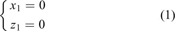

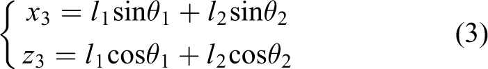


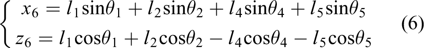
The position of the center of mass for each bar is


Record the hip joint coordinate as


Solve the above equation

According to Lagrange equation

L = T − U; T is the kinetic energy and U is the potential energy of the system. qk
is the angular velocity of the joint.


Some variables need to be numerical in the process of solving. This article assumes that the height of the model is 1.85 m and the weight is 90 kg. According to GB10000-88 (Chinese adult body size), 27 the proportion of human limbs can be calculated. The length of thigh is 0.38 m and the length of calf is 0.407 m. Other body sizes can also be calculated. Because joint angle is a generalized variable, it is necessary to collect the law of each joint angle of the lower limb. In this article, the wireless standalone sensing system (WSSS), which is developed by Shenyang CREASEN Hi Tech Co., Ltd, is used to capture the angle of human lower limb joints in real time. The WSSS wireless sensor system is shown in Figure 3.

WSSS of CREASEN (a) WSSS equipment and (b) walking experiment. WSSS = Wireless Standalone Sensing System. CREASEN is the corporation name for WSSS equipment.
This article selects five participants to walk. The ages of them are 27, 33, 46, 51, and 59 and the heights of them are 1.85 m, 1.85 m, 1.82 m, 1.84 m, and 1.83 m. Since the sampled data will be used to calculate joint torque, this article tries to choose samples with a height of 1.85 m, which will be the maximum height for people who are suitable for the exoskeleton proposed in this article. Each participant walks at a speed of 1 s/step along a straight experimental road with a length of 10 m which is recorded as one experiment. Each experiment repeats five times. A wireless acquisition module is respectively placed at waist, thigh, and calf. The collected data are automatically filtered in the wireless data acquisition system software and exported. For the same participant, calculate the average of the collected data at the same sample moment. In this way, a set of data for the same participant after five experiments can be obtained. Then curve fitting is carried out by MATLAB. The mathematical model of the curve is

ai and bi are the coefficients of the i-th trigonometric function. ω is the angular frequency. Finally, the motion angle curve of hip joint and knee joint with time is obtained as shown in Figure 4.
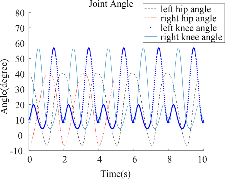
Motion angle curves of hip and knee joint.
The angle between torso and vertical plane changes from −2° to 2°.
28
Because the angle is small, this article assumes
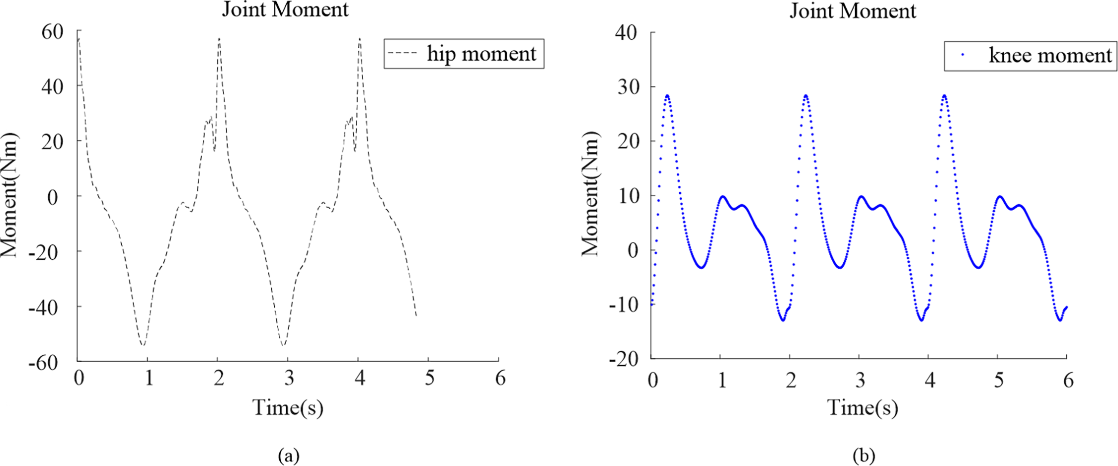
Moment curves for different joints: (a) hip joint and (b) knee joint.
In Figure 5, the moment of hip joint and knee joint changes periodically. Joint moment in walking state is related to human weight, leg size, and walking speed. When these variables are different, joint moment is also different. Therefore, when comparing with the existing results, only the shape, trend, and magnitude of curves can be compared. The shape and trend of curves in Figures 4 and 5 are nearly the same with the curves drawn by the clinical gait analysis (CGA) gait data of the International Society of Biomechanics, 29 the Hong Kong Polytechnic University, 30 and the research results of other scholars. 31 The maximum and minimum values of the curves are on the same order of magnitude.
Simulation and comparative analysis
To verify the correctness of the theoretical calculation, this article establishes a human rigid model in ADAMS. The body parameters of the model are the same as those of the theoretical calculation model, as shown in Figure 6(a). For human model, this article uses revolute pair to connect torso and thigh, thigh and calf, and calve and foot. Then the hip, knee, and ankle joints are formed. The rest of the body does not move during the simulation, so fixed constraints are used.

Simulation analysis result: (a) walking simulation, (b) moment curve of hip, and (c) moment curve of knee.
Apply rotary motor on hip joints, knee joints, and ankle joints. To make the model walk like a real person, angle matrixes for hip joint, knee joint, and ankle joint are imported into ADAMS. Cubic spline curve fitting is carried out by using the function CUBSPL in the joint motion model. Set the sole as a flexible body. Its material is rubber and the density is 10−6. Young’s modulus is 600. Poisson’s ratio is 0.33.
There is a contact constraint between the foot and the ground. Then the reaction force is automatically created in ADAMS. Set joint friction coefficient and gravity. ADAMS system provides a default joint friction coefficient: static friction coefficient is 0.5, dynamic friction coefficient is 0.3, friction arm is 1.0, and bending action arm is 1.0. During theoretical derivation, joint friction is not applied. To maintain consistency, the joint friction coefficient needs to be set to zero. Because the friction coefficient of human joints is very small, 32 it is acceptable to ignore the influence of joint friction on the simulation results.
After simulation, the moment curves of hip joint and knee joints are shown in Figure 6(b) and (c). (The original simulation figure is provided in Online Appendix 1.) The human model established in this article is not a biomechanical model but a rigid model. Therefore, there will be rigid collision in the process of movement. This will lead to large vibration and instantaneous impact of joint moment curve. But this does not affect the shape and trend of the curve. Comparing the theoretical results with that obtained by simulation, it is easy to find that there are some errors between them. But the basic trend is consistent, and the error magnitude is small, which is within the acceptable range. Therefore, the theoretical result is correct.
Structure design and electrical system design
Exoskeleton structure design
Different patients have different body size parameters. So exoskeleton needs to have size adjustment function. In this article, the exoskeleton is suitable for people whose height is 1.55–1.85 m and maximum weight is not more than 90 kg. According to GB10000-88 (Chinese adult body size), when body height changes from 1.85 m to 1.55 m, thigh length changes from 0.381 m to 0.319 m and calf length changes from 0.407 m to 0.341 m. The adjustment range for thigh length structure is 6.2 cm while the adjustment range for calf length structure is 6.6 cm.
At present, size adjustment mechanism for exoskeleton can be divided into two types: plane plate structure and tubular structure based on screw transmission. The two structures have their own advantages. For plane plate structure, it can be better fixed without relative rotation. But the disadvantage is that it is usually fixed by four or more screws. That makes adjustment complex and it is necessary to use special tools. The tubular structure uses screw thread for transmission which can realize size adjustment without tools. So it is easy to operate. But the disadvantage is that the shape is circular tube which is easy to produce relative rotation. In view of the advantages and disadvantages, three leg size adjustment structures are designed, as shown in Figure 7.

Leg length adjusting mechanism: (a) structure 1, (b) structure 2, and (c) structure 3.
To simplify the content, the detailed working principles for the three structures is introduced in Online Appendix 2. All of them can realize the length adjustment function, but structure 3 can be easily operated without any special tools. Therefore, this article selects it.
Assist joint is one of the most important components of exoskeleton. Therefore, the structure design for it is an important part in this article. The exoskeleton designed in this article is suitable for the height of 1.85 m and the maximum weight of 90 kg. According to the theoretical result in the “Dynamic model and solution” section, motor and reducer are selected. An integrated joint with the function of force perception is designed, as shown in Figure 8.

Joint design: (a) the whole structure, (b) section view, and (c) the torque sensor.
Figure 8(a) is the whole structure of the integrated joint, and Figure 8(b) is the section view of the integrated joint. The motor is a frameless torque motor with a continuous output torque of 0.73 N·m and peak torque of 0.95 N·m. The reducer is hollow cup harmonic reducer with a reduction ratio of 1:100. The encoder is multi-turn absolute encoder with 16 bit and synchronous serial interface (SSI). To make the joint having the function of force perception, this article designs a torque sensor. It is composed of an elastomer and a circuit board with torque range of 140 N·m, excitation voltage of 5 V, and sampling frequency of 1000 Hz. One strain gauge is pasted on each support arm of the spoke elastomer. The circuit board is placed inside the spoke elastomer. The inner ring of the torque sensor is connected with the output end of the reducer, and the outer ring of the torque sensor is connected with the output end of the joint. When there is torque at the output end of the joint, stress concentration occurs on support arms of the elastomer. At this time, change can be detected by the strain gauges. The torque value can be obtained by calculation through bridge circuit. The basic calculation theory can be referred to the relevant articles. 33,34 The cost of the torque sensor is less than 1000 RMB, which is far lower than the price of torque sensor in the market. The torque sensor is shown in Figure 8(c).
When the joint is powered on, the motor is in the enabled state. At this time, if there is a small amount of torque acting on the joint in any direction, the torque sensor can detect torque information. The torque sensor transmits the information to the exoskeleton controller through a cable. In this article, a nine-axis acceleration sensor is fixed on the inner wall of the exoskeleton control box. After the user wears the exoskeleton, the torso and the control box are fixed together by bandages. When the user moves, the nine-axis acceleration sensor can sensitively detect movement of the user in the vertical plane. The information is transmitted to the exoskeleton controller through cable. After analyzing the information of the nine-axis acceleration sensor and the torque sensor, the user’s motion trend is judged. Then the motor is driven to rotate. Finally, a structure design for lower limb exoskeleton is put forward as shown in Figure 9(a).

Exoskeleton design and simulation: (a) structure of the exoskeleton and (b) human–machine coupling kinematics simulation.
To verify that the exoskeleton does not interfere with human lower limbs during walking, a kinematic simulation of human–machine coupling is carried out in ADAMS. The exoskeleton model is fixed with the human rigid model. Rotary motors are added to hip joints and knee joints of the human model. Then angle curves of hip joint and knee joint are imported. Finally, dynamic interference alarm for parts is set in the system. The simulation result is shown in Figure 9(b). During the whole simulation, the system does not produce interference alarm. The man–machine coupling model can successfully complete walking simulation. Therefore, the exoskeleton designed in this article meets kinematic requirements.
Electrical system and board card design
To maintain balance during walking, this article provides two ways. The first way is to use a mobile scaffold. Fix the exoskeleton on the mobile scaffold and the mobile scaffold will provide balance guarantee for the exoskeleton. The second way is to use intelligent crutches. This article designs an intelligent crutch that can control exoskeleton movement. On the basis of ordinary crutches, a control box is designed. Bluetooth control board is installed in it and linked with the exoskeleton controller through Bluetooth. There are buttons on the Bluetooth control board. Users can use the buttons to control the exoskeleton.
Electrical system can connect all the electric parts. According to the function requirements, this article designs the exoskeleton electrical system, as shown in Figure 10.

Exoskeleton electrical system.
In electrical system, this article uses a 24-V 7-A·h lithium battery. It can effectively reduce the battery volume. The 24-V voltage is brought into power distribution board through adapter board. Because there are many electric parts, one 24-V voltage must be divided into five 24-V voltages by power distribution board. Then they are distributed to the main controller, fans, drivers, and the touch screen. Four drivers control four joints. In this article, joint control signals are feedback to a driver by an incremental encoder and an absolute encoder in the joint. The torque signal of torque sensor is sent to the main controller by cable. The communication between the main controller and drivers adopts Ethercat protocol, while the touch screen is connected with the main controller through Canopen protocol. In the main controller, there are Bluetooth module and Wi-Fi module. Bluetooth is used to connect crutch control board and Wi-Fi is used to connect pad.
The function of power distribution board is to manage power supply. It can realize soft start, power output, system power on and power off, and emergency stop. According to its function requirements, this article designs circuit diagram for each module on the board, as shown in Figure 11.

Function module design for power distribution board card: (a) design of control-electricity module and (b) design of power-electricity module.
To make the article brief, this paper introduces two key parts: control-electricity module and power electricity module. Figure 11(a) is the circuit for control-electricity module. The input part adopts ACPL-500E opto-coupler (Toshiba Devices and Storage (Shanghai) Co., Ltd. 5F, Wheelock Square 1717 West Nanjing Road, Jingan District, Shanghai, 200040, China). When there is an input signal, the opto-coupler is on. Then Q1 is on. System power begins to output. Figure 11(b) is the circuit for power-electricity module. The input part adopts TLP250 opto-coupler, which can directly output high and low level to drive the back-end circuit. When there is an input signal, the opto-coupler outputs high level and turns on the back end to control MOS. For emergency stop function module, when emergency stop button is pushed, the power output can be turned off.
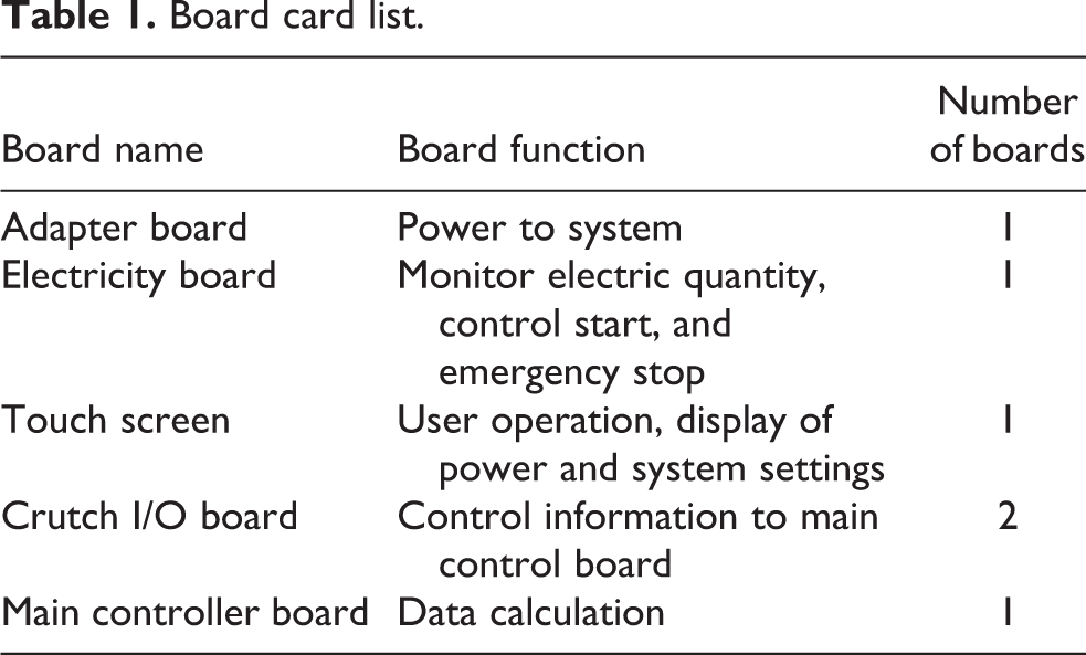
For crutch board, it has the functions of charging management, Bluetooth transmission, low-power sleep, and motion control. As shown in Figure 12, it is the design diagram of crutch board. It adopts TP4056 lithium battery charging chip (Toshiba Devices and Storage (Shanghai) Co., Ltd. 5F, Wheelock Square 1717 West Nanjing Road, Jingan District, Shanghai, 200040, China), which can charge up to 1 A. It has charging state indication. Type-C interface is adopted and is compatible with USB2.0 whose peak current of the system is about 20 mA. Finally, all boards are shown in Table 1.

Board design diagram of crutch: (a) front view and (b) back view.
Board card list.
Expert system development and experimental verification
Because the exoskeleton designed in this article is mainly used for rehabilitation, it is necessary to develop an expert system for gait training. Based on the design above, this article processes an experimental prototype and carries out a series tests.
Expert system development
The function of the expert system is to adjust gait parameters, gait types, and record information of rehabilitation trainings. In this article, gait parameters include stride length and speed while gait types include walking on flat ground, walking up slope, walking down slope, walking up stairs, walking down stairs, standing up, and sitting down. Doctors can use a pad or touch screen to set personalized parameters for patients. Then, the system will automatically match parameters to adjust the gait curve.
The expert system is developed based on real-time simulation platform (RSP). It includes four parts: (1) parameter adjustment module, (2) expected gait calculation module, (3) actual state calculation module, and (4) input communication module. Among the four modules, gait parameter adjustment module obtains gait, speed, stride, and other parameters through input communication module firstly. Then it transmits the information to the controller. Expected gait calculation module is to calculate gait trajectory in real time according to data models in gait information database. Parameters for joint motor running are generated and transmitted to drivers. Actual state calculation module reads information of current, position, and speed for drivers through Ethercat bus. It also reads power supply and other information through CAN bus. Finally, after the calculation, information is sent to control terminal for real-time display. As shown in Figure 13, it is the flowchart of the expert system.

Expert system.
In this article, there are three input terminals for the exoskeleton, which are touch screen on the control box, pad, and intelligent crutches. The priority from high to low for them is touch screen, pad, and intelligent crutch. Among them, touch screen and pad can set gait parameters, change gait types, and control the exoskeleton. But intelligent crutches can only control exoskeleton without the function of setting parameters and changing gait types.
For the gait data in gait database, this article collects a large number of gait samples. With the help of the Department of Orthopedics and Rehabilitation of The First Affiliated Hospital of Harbin Medical University, 500 volunteers are recruited. Among them, 233 volunteers are 20–40 years old, 95 volunteers are 40–60 years old, and 172 volunteers are 60–70 years old. According to the age distribution, 500 people are divided into three groups. They are labeled as young group, middle-aged group, and old group. Hip joint and knee joint angle curves for walking on a straight road, walking up stairs, walking down stairs, walking up slope, and walking down slope are collected respectively by using WSSS as shown in Figure 3. For the same gait type of each group, gait curve fitting is conducted. Then the common gait curve for this kind of gait for its group is obtained. The specific operation interface and operation mode is given in Online Appendix 3.
Experimental verification
To verify research results, a prototype is manufactured, as shown in Figure 14. For the purpose of expanding the range of applicable people, this article processes a mobile scaffold. The exoskeleton can be fixed on the mobile scaffold. For patients with insufficient upper limb strength and unable to control balance with intelligent crutches, they can use the mobile scaffold to train.

The prototype (a) front side and (b) back side.
To test the performance, this article carried out a durability test with load. The maximum weight of patients suitable for the exoskeleton is 90 kg and the highest speed is 1 s/step. Therefore, four 12-kg sandbags are placed on each leg of the exoskeleton and walking speed is set to 1 s/step. It is also the same as the theoretical analysis in the “Modelling and simulation” section. The length of lower limb is adjusted to the longest, which is suitable for patients with 1.85 m. Finally, 500-h running test is carried out for walking on flat ground, walking up stairs, walking down stairs, walking up slope, and walking down slope. The test prototype is shown in Figure 15(a). The test flowchart is shown in Figure 15(b).

Durability test: (a) test equipment and (b) test flowchart.
The test results show that each gait works normally and smoothly during the 500-h test and no fault occurs. Then standing up and sitting down is tested for 1000 times. The test results show that during the 1000 times test, the exoskeleton can work normally and stably without failure. The regulating mechanism is stable and reliable without damage, failure, abnormal vibration, and abnormal sound.
After performance test, an actual wearing performance test is conducted. Different people have different feelings about the same torque. So another purpose of this experiment is to obtain the participants’ subjective feelings walking with the exoskeleton. The test items are walking on flat ground test, walking up stairs test, walking down stairs test, walking up slope test, and walking down slope test, as shown in Figure 16(a) to (c). The test flowchart is shown in Figure 16(d). Among them, the flat walking test is carried out on a flat 25-m plastic road at a speed of 3 s/step. Three participants, with the height of 155–165 cm, 165–175 cm, and 175–185 cm respectively, are tested for five times for each one.

Performance tests: (a) walking test on flat ground, (b) up and down slope test, (c) up and down stairs test, and (d) experimental flowchart.
The test results are shown in Table 2. Walking up and down slope test is conducted on a 15- and 10-m length slope at a speed of 3 s/step. Three participants, whose heights are in the range of 155–165 cm, 165–175 cm, and 175–185 cm, repeat walking for five times. The test results are shown in Tables 3 and 4.
Test results for walking on flat ground.

Test results of walking up slope.

Test results of walking down slope.

Walking up and down stairs are tested on standard stairs with 20-cm height, width of not less than 22 cm. The number of stairs is 18 from one side to the other side. Due to the danger of walking up and down stairs, the walking speed is reduced to 6 s/step. Three wearers are in the range of 155–165 cm, 165–175 cm, and 175–185 cm, respectively. Each participant repeats five times. The test results are shown in Tables 5 and 6.
Test results of walking up stairs.

Test results of walking down stairs.

In Tables 2–5, “apparent” and “inapparent” are subjective feelings of participants. If participants can clearly feel joint assistance, the result is apparent. If participants cannot feel joint assistance, or feel joint assistance weak, the result is inapparent. From the results, most tests show that the exoskeleton has a very obvious power assist effect on lower limb joints. But assistance effect is not obvious in Tables 2 and 4 several times. This is due to the loosening of the flexible strap during walking. The exoskeleton is not tightly fixed with human body, resulting in partial power loss. From the above experiments, it indicates that the exoskeleton designed in this article has a good power assist effect. All components of the exoskeleton and adjustment structures are stable and reliable without damage, failure, abnormal vibration, and abnormal sound.
To test that the exoskeleton is really helpful for patients with lower limb dysfunction, four volunteers are recruited. The four volunteers are: one patient with brain injury (23 years old), two patients with spinal cord injury (35 years old and 20 years old), and one patient with severe stroke (78 years old), as shown in Figure 17(a) to (d). All of them are unable to stand before training and have to use wheelchairs to move.

Clinical tests: (a) patient with brain injury, (b) patient 1 with spinal cord injury, (c) severe stroke patients, (d) patient 2 with spinal cord injury, and (e) test flowchart.
The reason for selecting the four patients is that the patient with brain injury is closed brain injury. Such patients generally have no life-threatening and have better awareness. The patients with spinal cord injury are lower thoracic spinal cord injury (segments 6–12). Patients with upper thoracic spinal cord injury (segments 1–5) are often accompanied by syncope caused by postural hypotension during sitting down or standing up. Therefore, these patients are not suitable for exoskeleton. For stroke patients, as long as patient’s consciousness is clear and muscle tension can use exoskeleton for rehabilitation walking training under the judgment of doctors, they are suitable for exoskeleton.
The four patients are trained with the exoskeleton 8 weeks for 30 min in the morning and 30 min in the afternoon. On the last day of each week, they will walk without wearing exoskeleton for 30 min. The height between foot sole and ground of each step is collected by laser tracker for evaluating the rehabilitation effect. After the laser tracker collects the data, the mean value of data is calculated. Under the existing rehabilitation evaluation system, four doctors are selected to score. The mean value of the scores for four doctors is calculated as the test score of the patient this week. Figure 17(e) is the test flowchart.
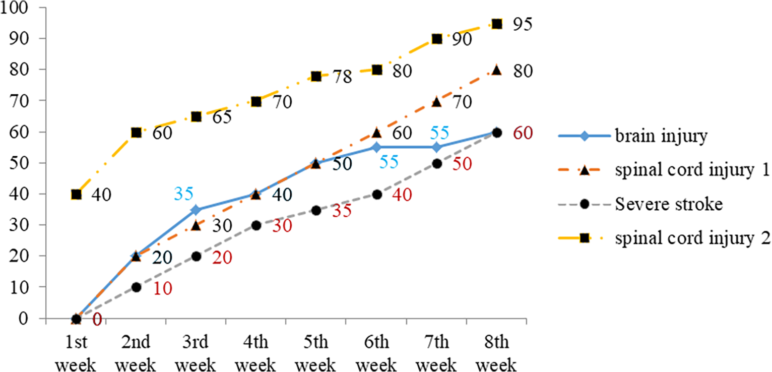
After 8 weeks training, weekly results are drawn into a table as shown in Figures 18 and 19.

Height of plantar to ground (cm).
Walking posture score.
In Figure 18, firstly two patients with spinal cord injury have the best recovery effect, followed by the patient with brain injury, and finally the patient with severe stroke. Because spinal cord injury patient 2 is younger than spinal cord injury patient 1, the recovery speed is faster and the recovery for lower limb lifting ability is higher. Secondly because of brain trauma, the patient with brain injury cannot completely recover from lower limb rehabilitation training. But he also improves significantly. Finally, the severe stroke patient is older, and he also suffers from other elderly diseases. Therefore, in his case the smallest rehabilitation effect is achieved and also the speed is the lowest among four participants. However, even his improvement is obvious in comparison to the level from the beginning of training.
In Figure 19, the doctors evaluate and score for walking gait. It can be seen from the results that the scores of patients with spinal cord injury are also higher, followed by the patient with brain injury, and finally the patient with severe stroke. The trend of score curve for patients with spinal cord injury is almost the same as that of the patient with stroke. The middle segment of score curve of the patient with brain injury appears to be bent. It is due to gait deformity caused by brain injury. So it is difficult to recover with lower limb rehabilitation training alone. Then, this article calculates the average value and standard deviation of 8-week data of each patient in Figures 18 and 19 respectively, as shown in Figure 20(a) and (b).

Mean and Std Dev analysis of (a) height and (b) walking posture score.
It can be seen from Figure 20(a) that the standard deviation of the data for the patient with severe stroke is the smallest. It means that the data fluctuate less near the average value. The average value is also the smallest, which indicates that during the 8-week rehabilitation training, the recovery effect is the smallest compared with the other three people. But the average value and standard deviation of the data of the patient 2 with spinal cord injury are the largest. Therefore, it indicates that his rehabilitation effect is the most obvious. It is consistent with the analysis results in Figure 18. The same rule can be found by analyzing Figure 20(b), which is consistent with the analysis results of Figure 19.
From the above tests, it can be seen that the components and adjustment structure of exoskeleton are stable and reliable, without damage, failure, abnormal vibration, and abnormal sound. Although the exoskeleton in lower limb rehabilitation of brain injury is slightly insufficient, it has a good rehabilitation effect on simple lower limb dysfunction. The test results are also consistent with the research results of other scholars. 35
Conclusion
In this article, the dynamic equation for simplified model of human lower limb is established, and variation law of joint torque is deduced. Then the correctness of the theoretical result is verified by dynamic simulation in ADAMS.
For structure design, firstly three kinds of leg adjustment structures for exoskeleton are proposed. They have the characteristics of simple structure, low cost, and lightweight. Secondly, a low-cost torque sensor for exoskeleton joint and a highly integrated joint are designed. The max output torque of the joint is 94 N·m, which meets the demand for the exoskeleton. As follows, a lightweight exoskeleton is put forward. Finally, a man–machine coupling simulation model is established, and a kinematic simulation is carried out. The simulation result shows that there is no interference during walking.
For system design, this article builds a 24-V electrical system and completes boards’ circuit design. To realize the intelligence, specialization, and visualization of exoskeleton control, an expert system for rehabilitation training is developed which can automatically recommend suitable gait parameters according to the patient’s gender, age, height, and weight. At the meantime, it can also record information of rehabilitation. Patients can also set various parameters to realize personalized training, which will help doctors make better training plan.
For experiment testing, a prototype is manufactured and tests are carried out. Firstly, the durability test results show that the mechanical system, electrical system, and control system have good stability and reliability. Secondly, wearing test results show that the exoskeleton can achieve the functional indexes. Finally, clinical test results show that the exoskeleton has significant effect in rehabilitation training. After using the exoskeleton in rehabilitation training for a period of time, their gait and walking posture are improved. Although the number and time of the tests are still relatively small, the positive effect of exoskeleton on the rehabilitation has been obvious.
Discussion
Through comparative analysis, it can be seen that: The exoskeleton joint proposed in this article is driven by motors, which is different from the preferences,
8
–10,12
There is no danger caused by rope break in the studies of Xie and Huang
8
and Cao et al.
12
At the meantime, the adjustment of leg length can be realized by hand without any tools. Although the torque of the exoskeleton joint in this article is not as large as the hydraulic joint in the study by Glowinski et al.,
9,10
it is sufficient for lower limb rehabilitation with a simpler structure and lighter weight. The exoskeleton leg proposed in this article includes hip joint, knee joint, and ankle joint, which is different from the studies by Zhou et al.
11
and Kim et al.
13
By this way, the weight of the device does not need to be carried by the users. The joint structure is also simpler than that in the study by Kim et al.,
13
which is more suitable for commercial transformation. Compared with the existing commercial exoskeleton products, the exoskeleton in this article realizes structural simplification and localization design. Compared with Rewalk, HAL, and Ekso, the exoskeleton in this article is low cost, which is less than 60,000 RMB. It is more suitable for the consumption level of Chinese people. Moreover, this article specially designed a rehabilitation training expert system for exoskeleton, which is not available in the above exoskeleton products. For rehabilitation effect, the age, condition, training intensity, and training environment of patients have significant effects on the rehabilitation effect, so this article cannot compare and evaluate the rehabilitation effect with other products. But it is clear that, through our clinical trials, the exoskeleton in this article has a satisfactory effect on lower limbs rehabilitation. The exoskeleton in this article can achieve the final rehabilitation effect of patients: significantly improve the lower limb movement ability.
Nevertheless, there are still some aspects that can be optimized and improved:
The boards in the control box can be further integrated.
The lightweight design of exoskeleton is realized by replacing metal materials with lightweight and high-strength composite materials.
Based on the development of bioelectrical sensing technology, under the condition of good cost control, EMG sensors can be used to realize motion prediction.
A large number of clinical experiments and comparative experiments are still needed to verify the rehabilitation effect of exoskeleton.
Supplemental material
Supplemental Material, sj-pdf-1-arx-10.1177_17298806221135140 - Dynamic analysis and design of a multipurpose lower limb exoskeleton for rehabilitation
Supplemental Material, sj-pdf-1-arx-10.1177_17298806221135140 for Dynamic analysis and design of a multipurpose lower limb exoskeleton for rehabilitation by Gang Li, Qiying Su, Wenqiu Xi, Zhendong Song, Renren Bao and Zhenjun Du in International Journal of Advanced Robotic Systems
Footnotes
Declaration of conflicting interests
The author(s) declared no potential conflicts of interest with respect to the research, authorship, and/or publication of this article.
Funding
The author(s) disclosed receipt of the following financial support for the research, authorship, and/or publication of this article: This research was supported by National Key R&D Program of China (2020YFC010222), National Key R&D Program of China (2020YFC2005803), and General Project of Natural Science Foundation of Guangdong Province (2022A1515010820).
Supplemental material
Supplemental material for this article is available online.
References
Supplementary Material
Please find the following supplemental material available below.
For Open Access articles published under a Creative Commons License, all supplemental material carries the same license as the article it is associated with.
For non-Open Access articles published, all supplemental material carries a non-exclusive license, and permission requests for re-use of supplemental material or any part of supplemental material shall be sent directly to the copyright owner as specified in the copyright notice associated with the article.