
Abstract
Active power-assist exoskeletons are becoming more prospective than follow-up types, especially for elderly and handicapped motion auxiliary. The exoskeleton is required not only to withstand load but also to actively share the weight of a human body. Active power-assist lower limb is designed to meet this expectation. The definition of “active power-assist” was suggested in this article. A unique man–machine motion mapping was derived based on the configuration matching, wherein the exoskeleton obtains the wearer’s motion data and parse out the corresponding intention. Man–machine coupling mechanisms were exquisitely configured, which rationalize the degrees of freedom of the man–machine system and facilitate force transmission for active assistant. The dynamic knees and hip joints with the integrated force servo unit were designed, which is the key to realize soft contact and cooperative movement. The prototype was developed, and three basic functions (human movement perception, force transmission, and movement cooperation) were preliminarily verified in a single leg swinging experiment. The effect of follow-up mode and active power-assist mode were quantitatively analyzed in marches-on-the-spot experiment. A 24.6% proportional reduction of the wearer foot force and smooth man–machine coordination in field experiments has demonstrated the feasibility of this structure design of active power-assist lower limb.
Introduction
Wearable exoskeleton robots which combine the human intelligence and flexibility with the power and accuracy of robotic system are showing great potential.1,2 The increasingly concerned lower limb exoskeletons are widely used for load carrying, walking aid, rehabilitation, and body support. According to their power-assisted effect, they can be subdivided into (1) follow-up type and (2) active power-assist type. The follow-up exoskeletons, which transfer the payload weight to the ground (not to the wearer) and follow the human body motion, are mostly used in load-bearing operations.3–5 Meanwhile, active power-assist-type exoskeletons treat the human body as a load and help reduce the human body energy consumption by actively assisting the wearer movements. This feature not only covers the load-carrying functions of follow-up type but also expands the movement performance of the wearer, which makes such exoskeletons quite lucrative for patients’ rehabilitation training, walking aids for the elderly and disabled persons, and military long-distance travels on rough terrain.6–9 However, it is still challenging to realize the active power-assist principle and structural design. 10
The first field-operational follow-up exoskeleton BLEEX was designed by Zoss et al. 11 at the UC Berkeley. The pilot and BLEEX have rigid mechanical connections at the torso, feet, thighs, and shanks. A sensitivity amplification control method 4 was proposed, which makes BLEEX equivalent to a mechanical system without inertia and friction via a dynamic feedforward mechanism. Since the exoskeleton was controlled not to exert any force on the human body, it can follow up human movement automatically. Yet, this method has a very high demand for the accuracy of the system dynamics model, 12 which becomes the main limitation for practical application.
Another follow-up exoskeleton HIT-LEX designed at Harbin Institute of Technology also aims at load carrying. Unlike the BLEEX, HIT-LEX measures the man–machine contact force on back and feet. Thereby, desired movement direction and speed of the wearer at contact points are identified, and velocity command for each active joints are derived according to the kinematics. This contact force–based follow-up control has effectively avoided precise dynamic modeling and still has good following effect.
With the increasing demand for exoskeleton robots in rehabilitation, help-age, and military areas, active power-assist type appears more competent than follow-up ones. The first commercially available version of the active kind was Hybrid Assistive Limb (HAL) 6 built by Cyberdyne Inc., Tsukuba, Japan. Human motion intention under the arbitrary state of motion is successfully perceived by calculating human joint torques according to the relevant surface electromyography (EMG) signals. Metal frames of HAL are strapped to the human torso, thighs, shanks, and feed, which allows proportional assistive torque transmission to the human body. Through this means, the human strength is amplified while still under the control of the human brain, and the man–machine soft contact and cooperation are guaranteed. This method has been widely adopted since then.7,13 However, a large number of electrodes attached to the human body makes the exoskeleton wearing not user-friendly. Moreover, redundant man–machine connection easily leads to motion interference.
Besides exoskeleton robots developed illustrated above, it is also necessary to mention the research work conducted on specific active-assist devices. An orthotic knee-extension assist developed at the Ottawa Hospital Research Institute 14 takes advantage of the gravity balance or the mechanical weight compensation method using a set of springs. Another research group at the Carnegie Mellon University reported that the metabolic rate of human walking could be reduced by an unpowered ankle exoskeleton by about 7% ± 3%. The lightweight elastic device, which acts in parallel with the user’s calf muscles, off-loading muscle force and thereby reducing the metabolic energy consumed in contractions, uses a mechanical clutch to hold a spring as it is stretched and relaxed by ankle movements when the foot is on the ground, helping to fulfill the function of the calf muscles and Achilles tendon. 15 MIT has designed the knee-assisted exoskeleton, 16 the spring which is placed in parallel with the knee to store the heel-strike energy and released when the heel leaves the ground, thereby reducing the metabolic cost of running. It can be seen that researchers are seeking for simpler and user-friendly solutions, yet such specific devices still lack flexibility, since the their mechanical structure and control algorithm have to comply with specific motion curve, which makes them hardly adaptable for the complex and changeable movements of the human body.
The above brief survey of the available exoskeleton robots has revealed that although the sensitivity amplification and the man–machine force interaction method can support arbitrary motion, they are limited to follow-up control. And some specified and simplified strategies are difficult to support arbitrary motion. Proportionally compensate the human muscular torque is a better choice for active power-assist, but the detection of human muscular torque is challenging, and the structure design is crucial.
This study is focused on structural design of an active power-assist lower limb (APAL) exoskeleton which can support random motion of human lower limbs. We intend to realize the functionality of HAL without using the EMG signal. A new structure is designed, which can detect motion data of human body in real time for muscular torques calculation, compensate proportionally with force servo joints, and transfer assistive force to human body softly and coordinately.
Main idea and prototype introduction
The active power-assist is defined as follows: the applied torque

The joint torque of human body can be reduced, only when
Based on the above definition, we mainly focus on the following functions of the mechanical structure:
First is establishing a unique motion mapping between the human body and the exoskeleton, so that we can acquire human motion data according to the sensing system in the exoskeleton structure, like a master–slave teleoperation robots. 18 Specifically, we equivalent the motion intention of the wearer to his or her muscular torque, as HAL does. 6 Difference is we plan to use inverse dynamics to calculate joint torque of human legs instead of EMG signals.
Second is transmitting assistive force to human body. The control objective of follow-up exoskeleton is to minimize and even eliminate the man–machine contact force. 4 On the contrary, the active power-assist exoskeleton would actively exert the applied force on the human body. For ankle assist, force can be added on shank and foot. 19 For knee assist, force is always added on thigh and shank, 20 or directly transfer from the thigh to the ground, 21 Those for body weight bearing, like the ReWalk 22 for patients with spinal cord injury and the walking assist exoskeleton 23 mainly apply force on the upper thigh and the torso. Question is which place of the human body can bear large force and how to avoid motion interference while connecting to the human body.
Third is coordinative motion with the wearer. There are two control centers in the man–machine coupled system. One is the human brain and the other is the exoskeleton controller. To ensure the wearer has the absolute initiative, in our opinion, the exoskeleton should only exert force on the human body, but not forcibly change the trajectory of human movement. Both the positioning servo and the speed servo strategy are not the best choice for the control of contact force because of the high stiffness. Common improvements include series elastic actuator 24 and impedance control with contact force feedback. 25 The former has inherent flexibility, but its frequency response is difficult to improve; the latter makes use of other elastomer in the mechanical system such as the band or the human tissue, but the accurate stiffness characteristic is hard to get which may cause instability of the control loop. Therefore, we want to design a power element with force servo ability which can track the desired torque curve rapidly and accurately.
We have designed the prototype APAL. As shown in Figure 1, the system consists of the backpack, hip suspension, hip joint, knee joint, ankle joint, and a joint drive device. The hydraulic power unit, control system, and cooling system are installed into the backpack. The sensing systems contain man–machine contact force sensor, joint angle sensor, and inertial navigation unit, while the valve-controlled hydraulic cylinders are adopted for actuators, and the high-performance programmable logic controller (PLC) from B&R was used for the controller. The weight of the whole machine is about 40 kg with the rated load of 45 kg, and the power-assisted coefficient of the human body can be adjusted from 0% to 25% with the maximum action speed of 1.5 m/s.

3D model of APAL.
Configuration design
Since the exoskeleton is a wearable device, its configuration, scale, and number of degrees of freedom (DOFs) should be similar to those of a human skeletal system. However, the difference in the spatial distribution would inevitably lead to the incomplete agreement between them. Moreover, it is necessary to remove some insignificant elements and employ equivalent mechanism transformation to reduce its complexity. The designed configuration of the APAL is shown in Figure 2.

APAL exoskeleton and the distribution of DOFs (red lines correspond to actuated joints with Joint drive element, blue ones to passive joints).
For hip joints, three rotational DOFs are adopted to simulate the spherical hinge function of the human hip joint. Flexion/extension DOF has the greatest influence on the foot movement space. Therefore, 2 DOFs are realized using a rotating pair with an axis passing through the spherical center of a human hip joint, so as to reduce the man–machine motion interference. Supination/pronation DOF mainly affects the foot posture. Although the motion range reaches ±45°, the motion amplitude caused by this DOF is small. To facilitate the structural design, the axis of this DOF is transferred laterally to the outside of the human hip. The DOF of hip side-sway is jointly realized by the side-sway joints set on the outside and the waist.
The human knee joint is a synovial joint, and its kinematics characteristic is complicated. However, the overall performance mainly corresponds to the flexion/extension DOF. Therefore, a revolute joint is used for the knee joint. Since this simplified design will lead to a relative motion between the exoskeleton and the human knee joint, it is inappropriate to connect exoskeleton knee to human body.
The ankle joint can also be regarded as a spherical hinge, which possesses dorsiflexion/plantar flexion, ectropion/introversion, and abduction/adduction DOFs. Among these, the motion range of dorsiflexion/plantar DOF is the largest, and this DOF is the key to ensure a good contact between foot and ground. Therefore, it is realized using the rotational DOF with an axis passing through the spherical center of a human ankle joint. Ectropion/introversion is critical to adjust the movement balance in the left and right directions, which must be retained. However, since the length of rotating arm of this DOF is short (about 80 mm), the translation of the axis to the outside will not cause significant man–machine relative movements.
The ankle abduction/adduction DOF needs careful consideration because the function of this DOF is repetitive to that of hip joint internal/external rotation. If both DOFs are set on the exoskeleton, the rotational movement of the exoskeleton legs will be uncertain, which would lead to the ambiguous mapping relationship between human and exoskeleton motions. Therefore, the latter DOF is excluded.
Man–machine coupling mechanism
The man–machine coupling mechanism is the physical boundary between the wearer and the exoskeleton robot. The key point includes kinematic coupling, force transmission, and DOF matching. The kinematic coupling ensures the complete accordance of human body and exoskeleton at the connection point. The force transmission function allows transfer of the assistive force to proper points on human body. The DOF matching ensures that the DOFs of the man–machine coupling system are same as those of a human body.
An effective way to reduce load on human body is to set up a force transmitting bypass. Hence, we have to identify the source, the path transmitted to the ground, and the set location of the connection point of the load. Obviously, the body weight is the source of the load. It consists of gravity, inertia, and friction. The load produced in each part of human body passes along latter limbs until to the ground, causing joint forces and moments.
Torso coupling
For the stance phase, the main load comes from the human torso (including the head and arms), and the cumulative stress in the force transfer channel on human body (including the spine, pelvis, thigh, shank, and foot) gradually increases. Here, we choose torso as one connect point. Thus, the force conduction bypasses from the human torso to the ground and will release the whole load transfer channel on human body.
The pelvis is an interface between the torso and legs. It can bear heavy loads, and almost no distortion occurs during movement. Therefore, we choose pelvis as the main force transmission area on the torso. The hypertrophic iliac crest on the edge of the pelvis can bear the vertical force. The ilium wings, which protrude outward on both sides, can bear the lateral forces. The anterior superior iliac spine and posterior one can bear the forward and reverse directed forces, respectively. Meanwhile, since the pelvis width obviously exceeds its thickness, it can be used to bear the torque around the spine. Thus, the pelvis can bear the three-directional forces and one torque moment, while the remaining two (pitch and rolling) moments have to be transferred to the shoulders. The upward force of the exoskeleton exerted on the human body is transmitted through the chest belt set at the lower rib. The exoskeleton strap scheme is shown in Figure 3(a). The straps and the backpack-like box of the exoskeleton are connected by force sensor to ensure the direct measurement of the interaction force between the human body and exoskeleton in the back.
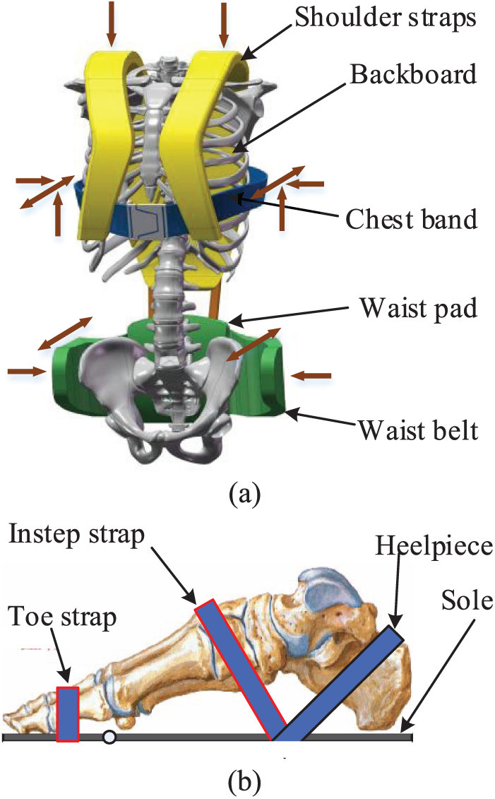
Man–machine coupling mechanisms: (a) torso and (b) foot.
Foot coupling
For a swing leg, hip joint is the base, and foot is the terminal. If we want to release hip and knee joint, we will neither hold the thigh nor the shank. Instead, connect point on the foot end should be set up.
The man–machine coupling mechanism on the foot enables the synchronous movements. Meanwhile, human hip and knee joint torque could be reduced in the swing phase stage since the exoskeleton can lift the wearer foot. The foot connection is shown in Figure 3(b). Due to the difference in the exoskeleton and the joint distributions, as well as to the individual human body dimensions, the exoskeleton and human lower limbs will not be fully consistent in the movement process. To avoid the motion interference, the exoskeleton lower limb is not firmly connected to the human leg, and instead, a fixed constraint is applied only to the human foot, which can be roughly subdivided into foot arch and toes. The foot arch is a rigid body. The exoskeleton shoe is firmly connected to the foot arch with a hard flat zone at the back of the sole. Three DOFs are constrained between this zone and the plantar plane. The lateral, forward, and backward DOFs are further constrained by the instep and heel bandages (Figure 3(b)). Besides, a strap is placed at the toe, along with the other two straps, to limit the rotational DOF around the shank axis. The front end of the sole can be flexed to fit the rotation of toe joints. Similar to coupling device on torso, a force sensor is installed between a human foot and exoskeleton, which can measure the force and torque of the wearer’s sole.
DOFs of the man–machine coupling system
A human body and an exoskeleton can be considered as two independent serial mechanical systems. When the two systems get coupled, the connect points and the connecting mechanism will influence the DOFs of the coupling system. In our opinion, the condition where the exoskeleton does not interfere with the movement of the human body is that the number of DOFs of the man–machine coupling system is not smaller than that of the human body. Meanwhile, the condition which ensures a uniquely determined motion mapping relationship between the exoskeleton and the human body is that the number of DOFs of the exoskeleton is not larger than that of the human body. The DOFs of human, machine, and man–machine coupling system are depicted in Figure 4.

DOFs of (a) human and (b) machine and man–machine coupling system.
As shown in Figure 4, the subject is standing on one foot, and only lower limbs are taken into consideration. The pelvis and torso are regarded as a whole. Ignoring the synovial characteristics of knee joint as well as the DOF of the toes, the human model consists of seven components. The foot of the supporting leg is restrained by 6 DOFs of the ground. For the hip and ankle joints, four spherical hinges with three restrictions are used, while two knee joints are constrained by five hinges. Therefore, the DOF of the human model is

When the designed exoskeleton has one foot on the ground, the number of the components is 13, the number of rotational joints is 12, all the rotational joints are constrained by 5 DOFs, and the foot of supporting leg is restrained by 6 DOFs of the ground. Therefore, the number of DOFs of the exoskeleton is

After being connected to the exoskeleton, the human torso and feet are rigidly connected with it, and the total number of components in the system is 17. The plantar restraint of the supporting human leg is no longer the ground, but the exoskeleton shoe, and the number of DOFs of the man–machine coupling system is

It can be observed that the DOF of man–machine coupling system is same as the DOF of the human body. Meanwhile, there are 6 DOFs for the unilateral exoskeleton leg, so that a foot may reach any position of the motion space in any posture. The mapping relationship between the foot coordinate values in the body axis system and the angles of six rotational joints of the leg is uniquely determined.
Joint drive configuration
Joint drive element
According to the requirement of man–machine coordinated control, the joint drive components need the functions of torque servo control and the joint angle measurement. Meanwhile, the characteristics of high-power density and good dynamic response are required. We have designed a miniature integrated hydraulic servo unit, as shown in Figure 5, wherein the asymmetric hydraulic cylinder is adopted as the power element. At the tailpiece of the piston rod, the integrated force sensor is used for the force servo feedback. A resistance-type displacement sensor is arranged parallel to the piston rod to measure and calculate the stroke of the piston rod and then the angle and angular velocity of exoskeleton joint are derived. The linear bearing is used for preventing the failure of displacement sensor caused by the rotation of piston rod. The rated pressure of the hydraulic cylinder is 18 MPa, the exportable thrust is 6838 N, and the tensile force is 4068 N.

Integration hydraulic servo unit.
Knee joint mechanism
The knee joint employs the three-rod mechanism, as shown in Figure 6(a).

Powered (a) knee and (b) hip joints.
The kinematical equation can be deduced according to the geometrical relationship. The relationship between the length of the hydraulic cylinder

To facilitate the control of the joint torque, the relationship between the moment arm
Hip joint mechanism
The drive mechanism of the hip joint is relatively complicated. For the exoskeleton robot without additional lumbar pitch joint, its angle range of hip joint should take account of both the flexion and extension range of human hip joint (−15°~125°) and the pitch range of lumbar spine (0°~25°), which enables the wearer to accomplish squat. Therefore, the required motion range should exceed the individual one of the hip joint. Therefore, the angle range of hip joint is set as −15°~150°. The limit motion range of conventional crank-rocker mechanism is 180°. In fact, when the angle between the crank and the rocker is very small, the equivalent moment arm is too short, which leads to a very low output torque, and cannot satisfy the requirement. Meanwhile, the drastic change of this equivalent arm of force is strongly nonlinear, which is not beneficial for the stability of the control system. Therefore, we designed a multi-link drive mechanism shown in Figure 6(b) to reduce the variation range of the equivalent moment arm.
Similarly, according to the geometrical relationship, the dependence

(a) Hip joint angle versus cylinder length and (b) equivalent arm of the hip joint cylinder versus its length.
The relationship between the cylinder force

Thereby

where
Experimental performance
To verify the actual power-assisted effect of APAL, comprehensive experiments were performed for a single leg and the total system, as well as the full-scale.
Motion information perception and joint torque tracking experiment
The purpose of this experiment is to test the motion intention perceptive function of the exoskeleton related to the human swing leg and the torque servo function of the exoskeleton joint. The tester wears the exoskeleton and has one leg swinging. The swing frequency is about 26 times per minute.
The control strategy is shown in Figure 8. Inertial measurement unit (IMU) and joint sensors detect the torso posture and joint angle

Control strategy of active power-assist.
The torque curve of the hip and knee joints tracking the target joint torque with a force servo mode are shown in Figure 9(a) and (b), respectively, where the red curve is the target joint torque solved in real time by the human motion information combined with the inverse dynamics model of man–machine coupling system. Under this torque, the exoskeleton can not only balance its own mass force and friction force but also exert force on the human body according to the set proportion. The blue curve is the actual output joint torque of thee exoskeleton. Generally, the exoskeleton joint driver can properly track the target torque curve, but due to the disturbance of joint velocity, the forward and reverse motion switching of the asymmetric hydraulic cylinder leads to a sudden change in piston area and results in the servo error. Meanwhile, drastic changes of the static/kinetic friction coefficients of the hydraulic dynamics cause the difference between the actual and target torques, especially when the target torque is small (such as the knee joint of swing phase), so the relative error is increased. When the target torque is larger (such as the supporting phase), the error could be relatively small.

Target and actual joint torques of (a) hip and (b) knee joints.
Test of the integrated system
To quantitatively test the effect of the active power-assist function, a comprehensive comparison test is carried out for the joint zero torque, follow-up, and active power-assist modes. By recording the man–machine contact force information of the back and sole under the three modes, the power-assisted effects of the exoskeleton on the human body are quantitatively assessed.
The height of the wearer is 180 cm, and the weight is 75 kg. After putting on the exoskeleton, the wearer marches on the spot under zero torque, follow-up, and active power-assist modes, respectively, whereas, in the latter case, the power-assist coefficient is set as 25%. The stride frequency is about 90 times per minute. The recorded data are shown in Figure 10. The back force can be regarded as the applied force, which is exerted on the human body. The upward direction is treated as positive, and the downward one as negative.

Foot force and back force under three different modes.
From the back force curve it can be seen that, under the joint zero torque mode, the wearer bears almost the entire weight of the exoskeleton, with a mean back force value of −370 N. After entering the follow-up mode, the mean back force value is significantly reduced to −13 N, which indicates that the exoskeleton bears the most of its own weight. After the active power-assist mode is activated, the back force turns from negative to positive, which means the exoskeleton fulfills the task of lifting the wearer trunk upward and helps the wearer to bear his or her body weight.
The foot force curve records the sum of the supporting forces of the human feet from the ground, and the greater foot force implies the greater stress of human lower limb muscles and vice versa. From the experimental curve, it can be seen that, after the active power-assist, the mean foot force value is reduced by 24.6% (from 740 N of the follow-up mode to 558 N), which is close to the preset power-assist coefficient of 25%. The experimental results strongly suggest that the designed APAL robot provides the human motion following and realizes the expected active power-assist coefficient.
Functionality experiment
We have also tested the coordination between exoskeleton and human movement under complicated motion forms, including walking on rough ground, stair climbing, and obstacle crossing, which are shown in Figure 11(a)–(c), respectively.
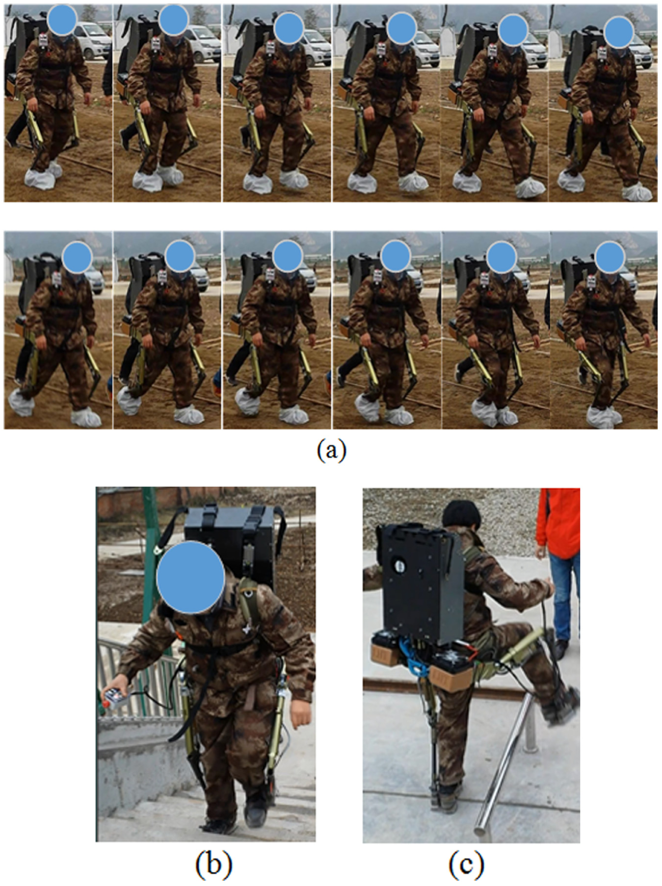
(a) Walking test on rough ground, (b) stairs climbing, and (c) obstacle crossing tests.
The following characteristics of the proposed prototype are found from the experimental functionality test. First, the disturbance to the wearer’s body movements is small because the exoskeleton robot is strapped only to the torso and feet, while thighs and calves are free. Second, under any motion conditions of the wearer, the exoskeleton can complete the actions coordinated with the human body, which indicates that proposed configuration ensures the uniquely mapping relationship of man–machine motion information and realizes the real-time sensing of human motion intention. Moreover, although the prototype weight reaches 40 kg, the active energy assistance is exerted to the human body. When the wearer’s foot is lifted, the exoskeleton actively lifts the sole; and when the wearer does stretching, squat, and stairs climbing, the exoskeleton actively provides the wearer with elevating power through the chest belt. The proposed structure achieves the controllable active power-assist through the multi-joint linkage.
Conclusion
This article newly proposed the structure of an APAL exoskeleton. The definition of active power-assist was clarified and functional requirement was analyzed, and our implementation scheme was systematically elaborated. Based on the matching of the human skeleton and the lower limb exoskeleton configurations, the unique man–machine motion mapping was derived for an accurate human motion intention perception. Man–machine coupling points are demonstratively selected at feet and torso for transferring assistive force to human body. DOFs of both human and man–machine coupling system were calculated to conform equality and no restriction to human movement. A micro-integrated servo hydraulic cylinder with force servo control ability and the hip/knee dynamic joints was designed, which meets the requirement of the proportional joint torque compensation and angle displacement measurement. The feasibility of the proposed structure was verified by the experiments on walking on rough ground, stair climbing, and obstacle crossing. The comprehensive analysis of the experimental results obtained for the lower limb power-assist coefficient of 25% and the total prototype operation has demonstrated a good coordination between human and exoskeleton movements for the complicated motion forms.
The proposed version of the prototype is primarily for implementing functions and verifying the basic algorithms. Our future work will mainly focus on the effects of the residual load of unpowered joints on wearers, the dynamic feedforward control, and low-energy consumption joint driving method.
Footnotes
Handling Editor: Tadeusz Mikolajczyk
Declaration of conflicting interests
The author(s) declared no potential conflicts of interest with respect to the research, authorship, and/or publication of this article.
Funding
The authors disclosed receipt of the following financial support for the research, authorship, and/or publication of this article: This work was supported by “National Defense Basic Science Research Program of China” (grant no. B2320133005).