
Abstract
A new kind of 18 degrees of freedom gantry robot with multiple manipulators could be used to complete the double-sided laser beam welding of stringer–skin T-shape structure for aircraft skin. The coordination control combined with error allocation model analysis is proposed to improve the stability and accuracy of the robot in this article. Firstly, the error model of the stringer–skin T-shape structure welding robot end effectors is analyzed. The score of the robot end effectors position error caused by each joint is obtained. Secondly, according to the path-points transformation matrix of the local coordinate system relative to the base coordinate system, the desired position of stringer–skin T-shape structure welding robot end effectors is calculated to be the input of the control model aiming at the dual-beam laser welding process. Then, the double closed-loop control strategy is proposed for stringer–skin T-shape structure welding robot coordinated motion on the basis of the end error analysis results and proportional-integralderivative (PID) method. Finally, ADAMS and MATLAB are used to establish a co-simulation platform to verify the effectiveness of the proposed coordination control strategy.
Introduction
Laser beam welding is a promising technique because of the widely applied lightweight materials under the circumstance of the increasing global demand for improved fuel efficiency and the reduction of carbon emissions. 1 Its advantages are over the conventional joining process with the characteristics such as low heat input, high power density, high welding speed, narrow heat-affected zone, higher depth-to-width ratio of the bead, and low distortion. 2 –4 Laser welding technologies have been extensively growing for industry including automotive production, shipbuilding, and pipeline transport. 5 –7 A welding technique that combines two high-energy beam sources, either electron beams or laser beams, 8,9 called “dual-beam welding,” has been investigated in recent years. The tensile strength and elongation were both increased under dual-beam laser welding compared with those under single-beam laser welding. 10 It has been proved that the use of dual laser beams has been demonstrated to improve the wettability, weld width, and mechanical properties of aluminum–steel weld joints. 11,12 It can meet the performance requirements and standards of metal joints. 13 In the aviation field, the welding quality of T-shape structure of stiffened panels on aircraft skin is very important. Dual-beam laser welding has been successfully applied to the welding of the lower panel of Airbus A380 nose. 14 Accordingly, the dual-beam laser welding equipment was developed by the Bremen Institute of Radiation, Helmholtz Association, Fraunhofer Institute 15 for Materials and Radiology, Hannover Laser Institute, Aachen University of Technology, and other scientific research institutes to apply the dual-beam laser welding technology.
Due to the large size of stringer–skin T-shape structure weldments, it is difficult for the traditional pieces of welding equipment to complete the operation of structural parts with a length of more than 3 m at one time. Therefore, the mechanical system for dual-beam laser welding needs to have the characteristics of large structural size, large span, and long stroke structure with high stability, low failure rate, and high machining precision. Industrial robots generally have two main functions, namely “mobile” and “operation.” The structure of a mobile robot usually depends on the robot working environment. Generally speaking, mobile robots undertake the moving tasks on land, in the air/space and the sea respectively. Manipulators are responsible for different operations according to their different end effectors, as shown in Figure 1.

Mobile and operation robot system.
The simultaneous completion of stringer clamping and bilateral seam welding is the guarantee for the effective completion of T-shape structure weldments connection. Compared with the single robot, the multi-robot system has the advantages of good flexibility and high reliability to complete these tasks. “Mobile and operation” robot system would be a good choice to realize the operation of the large-sized welded structures. 16 Combining the advantages of multi-robot system and “Mobile and operation” robot system, the dual-beam laser welding technology could be effectively used in the welding of T-shape structure weldments in aerospace. Simultaneous welding with two beams brings forward higher demands on the control and maintenance of the mechanical system. 17 The robot control method based on dynamic modeling is complex in engineering practice. 18,19 Hjalmarsson et al. 20 introduced that the parameters of the feedback controller can be adjusted iteratively to compensate the model easily. The source of feedback can be various equipment. Compared with the new type of human voice feedback control welding robot, 21 the development of sensors such as laser and vision in the field of weld tracking has been more mature. 22,23
The feedback control is used in some welding robotic research studies. Guo et al. 24 presented a new feedback control method of all position welding robot system based on visual sensor, which was verified based on Visual Studio platform. Based on GT-SG-400 motion controller, Li et al. 25 developed a kind of three-degree-of-freedom planar curved seam automatic welder, making sure the gesture demand of welding gun perpendicular to welder all the time. Based on the automatic control algorithm of PD controller and enhanced learning controller, the trajectory planning and tracking in the welding process of welding manipulators are realized, and the tracking errors of the manipulator joint are obviously reduced. 26 A segmented self-adaptive proportional-integral-derivative (PID) controller is introduced to the system, the accuracy of the technology can meet the requirements of quality control of seam forming. 27 The proposed method by Wang et al. 28 features data-driven iterative compensation of torque and motor reference. Depending on the specific setup of end effector sensing, the method can utilize either timed trajectory measurement or untimed two-dimensional contour inspection. Literature 29 –31 uses neural network control, fuzzy control, and other methods to compensate the error and achieves good control effect. It is hard to say its effectiveness in coordination control of the dual-beam laser welding robot with multiple manipulators.
The traditional multi-robot system has independent operating objects. The kinematics and dynamics models of each manipulator are independent, and there is no directly mutual interference between the manipulator. Each manipulator is directly in contact with the independent operating object and completes the given task through the end actuator operating object. The dual-beam laser welding robot with multiple manipulators for stringer–skin T-shape structure is different as multiple manipulators are connected and cooperative. The error of robot end effectors caused by kinematic error will affect the response time and robustness of the robot control link. 32 Establishing the error model of the robot could provide guidance for the control of the robot. However, the error of the end effector position of each manipulator could not be directly solved as it is impossible to directly refer to the control method of single welding manipulator or traditional robot system.
In this article, a double closed-loop control strategy on the basis of the coupled levels of hierarchical planning is proposed so that the dual-beam laser welding robot joints could achieve the purpose of coordinated and synchronous motion. There is no master–slave in each part of the robot control system, and the movement of all joints could be affected by other parts. The problem that the closed-loop inverse kinematics control algorithm is too time-consuming and complex under the condition of unknown dynamic parameters of the dependent manipulators and the operating object and strong coupling of the system could be effectively solved. The integrated dual-beam laser welding robot with multiple manipulators can still ensure high-precision trajectory control while increasing the workspace. The major contributions can be summarized as follows: An error allocation model is established to quantitatively analyze the influence of robot joints on the end effectors during dual-beam laser welding process. The double closed-loop coordination strategy is proposed for stringer–skin T-shape structure welding robot based on the desired movement of the robot end effectors and joints, which is achieved by allocating the robot end effector position error and then compensating to the inner loop. The dual-beam welding task conducted by the robot with multiple manipulators is applied on the established cosimulation platform to verify the effectiveness of the control strategy.
The rest of this article is organized as follows. The second section is the dual-beam welding process of stringer–skin T-shape structure welding robot with multiple manipulators. The third section details kinematic error calculation. The fourth section shows the coordination control strategy. In the fifth section, co-simulation for T-shape structure welding robot is performed. The final section gives conclusions.
Dual-beam welding process of stringer–skin T-shape structure welding robot with multiple manipulators
The thickness of the stringer and the skin which constructed the T-shape structure is 2 mm. Dual-beam laser welding task is shown in Figure 2. The double-sided seam of a stringer could be welded at one time when the welding robot could move in a wide range. The incident angles of the left and right laser beams are α 1, α 2. For example, α 1 is the angle between the left beam axis and the tangent plane A1. In the process of dual-beam laser welding for stringer–skin T-shape structure, the position of beam focus is very important.

Dual-beam laser welding task.
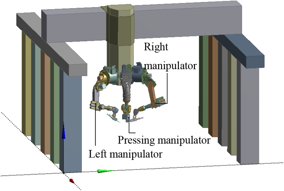
The left and right welding manipulator of the welding robot with multiple degrees of freedom movement ability is used for welding the double-sided three-dimensional seams of T-shape structure. The welding manipulator end effector is responsible for the left welding seam, as shown in Figure 3(a). The left and right welding manipulators are two six-axis KUKA KR16 manipulators. The middle manipulator is used to press the stringer, as shown in Figure 3(b), which is a three-axis KUKA KR180 manipulator. The three manipulators are installed on the three-DOF gantry in the form of upside down. Their composition is shown in Table 1. The gantry could be regarded as three prismatic joints, namely J11, J12, J13. The robot model with working posture is established, as shown in Figure 4.
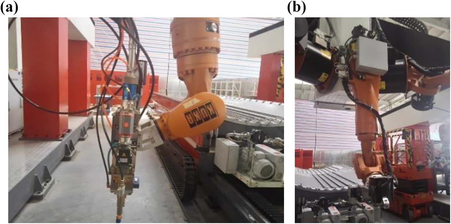
Composition of the welding robot: (a) the end of the left manipulator and (b) the middle manipulator.
The composition of robot manipulators.

Position and attitude of the robot.
Kinematic error calculation
Robot end effectors error model
The movement of stringer–skin T-shape structure welding robot joints is represented by θij
. Joints’ coordinate systems (XijYijZij
, i = 1, 2, 3; j = 1, 2,…,6) and homogeneous transformation matrices


Robot coordinate systems.
The differential movement of the joint included differential translation and differential rotation, which would lead to the error of the robot end effectors. Differential deviation motion relative to base coordinate system is δθij
. The new synthesis transformation matrices of robot end effectors represented by

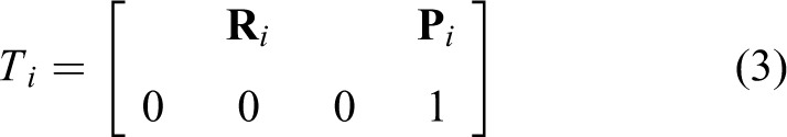
The position and attitude matrices of the robot end effectors could be defined as
where

where Δ
Obviously, the deviation in a certain moving direction of the three-DOF gantry would directly cause an equal amount of position error at three end effectors. In addition, the movement deviation of the prismatic joints is not suitable to be compared with the rotation deviation of the rotate joints due to different units. Therefore, we focus on the position error of the end effectors caused by 15 revolute joints of the welding robot. The number of the dual-beam laser welding process discrete time nodes is N, and the position error of the robot end effectors in X-axis, Y-axis, and Z-axis is
The vector of position error of robot end effectors in base coordinate system is

where u, v, and w are unit vectors in X-axis, Y-axis, and Z-axis, respectively.
Through data of

The error of the middle manipulator end effector.

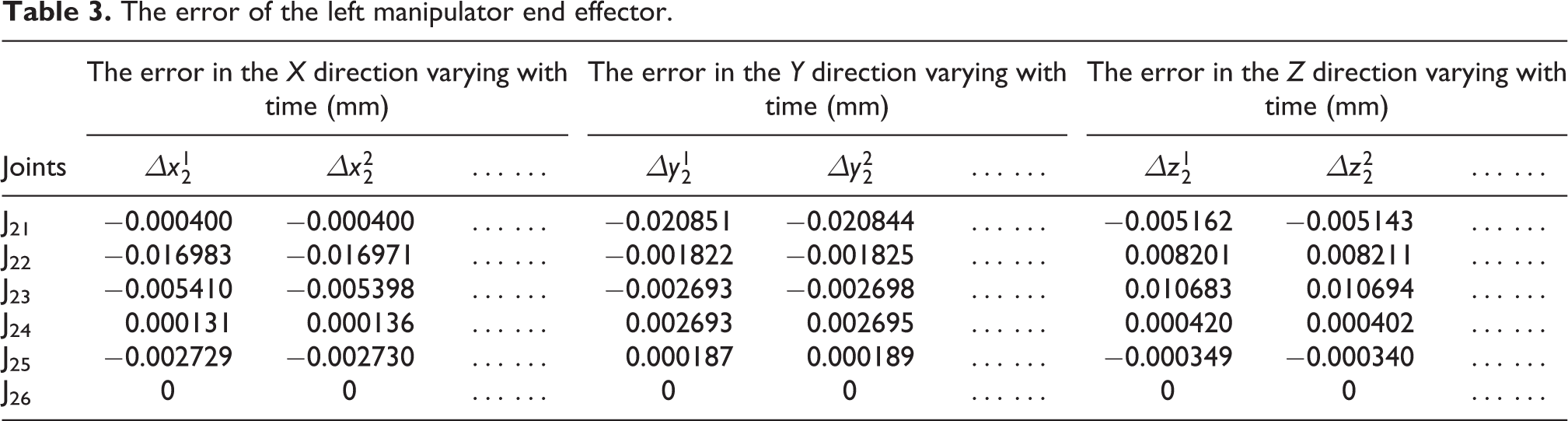
The error of the left manipulator end effector.
The error of the right manipulator end effector.

Error allocation parameter
Through equations (5) and (6), the position error of end effectors Δpi could be obtained and analyzed. To intuitively reflect the impact of joints deviation on Δpi , the quantitative results of welding robot end effectors are displayed with box-plot in Figure 6. According to Figure 6(a), J15 has more influence on middle manipulator end effector than J14. For the whole dual-beam laser welding operation, the influence of J14 changes more violently. According to Figure 6(b) and (c), we could get a relatively consistent regulation that the joints of left and right upper manipulators ((J21, J22, J23) and (J31, J32, J33)) has more influence on lower manipulators ((J24, J25, J26) and (J34, J35, J36)). As topological structure and size parameters of the left manipulator and right manipulator are consistent, the influence of the manipulator joints on their end effectors is similar. However, the assembly mode of left and right manipulators which is not mirror symmetrical brings into the slight difference.

The synthetic position error of welding robot three end effectors: (a) error of middle manipulator end effector, (b) error of left manipulator end effector, and (c) error of right manipulator end effector.
The comprehensive error caused by deviations of 15 joints valued by the box-plot is more intuitive than the equations (5) and (6). In fact, the influence of 15 joints on the error of three end effectors around X-axis, Y-axis, and Z-axis could be obtained in the same way.
Based on the data of


where N max is the maximum time nodes of the whole dual-beam laser welding process.
The average value is regarded as the score of each joint on position error of the end effector. According to Tables 2
to 4, the joints J16, J26, J36 only affect the attitude of the end effectors but not the position. Therefore,
Based on the structural characteristics of the robot, the average value of position error of the end effectors
Correspondingly, the error allocation parameters
Coordination control strategy
To minimize the error of stringer–skin T-shape structure welding robot with multiple manipulators, a simple control strategy which could reduce the error to the full is needed. PID has a simple structure and strong robustness against the outside interference. Thus, PID is widely used in the intelligent control in many fields, not only manipulators but also parallel mechanisms.
33
θij
is the angle of the multi-joints robot. The desired joint position is represented by

Desired movement
N × 3 discrete points
Due to the orthogonality of the coordinate axes,

Take the point

When working on points

The tool coordinate system of the middle manipulator is coincident with the local coordinate system of


Coordination control
Based on PID controller, 18 joints movement could be controlled. The PID joint-space feedback controller generating joint forces and torques τ is shown in equation (17). The joint error εij (t) is read and sent command to the controller to drive the multiple joints’ move

where Kpε(t) is a proportional control, Kp
is the proportional control gain acting as a virtual spring that tries to reduce the εij
(t). Ti
is the integral gain and could be used to reduce or eliminate steady-state error. The derivative gain Td
acts as a virtual damper that tries to reduce the velocity error
The traditional robot PID controller could not eliminate the robot end effectors position error effectively. Due to the development of intelligent vision and sensors, the idea of “hierarchical planning” for coordination control is proposed as the error detection of the end effectors is easier. Sensors provide the end effectors position error Δpi , and controller provides the joints position error εij (t), adjusting the movement of robot joints together, which is shown in Figure 7 from the top to bottom.

Hierarchical planning.
A double closed-loop control strategy is provided to ensure the overall accuracy requirements of T-shape structure welding robot. The error between the desired position and the actual position of the end effectors in X, Y, and Z directions is obtained and respectively transmitted to the joints error through the allocation which is based on the kinematic error of each joint on the end effector. The cooperative control is different from the parallel control between the joints, which does not affect each other. When controlling the motion of one of the joints, not only the information of a single joint is considered, but the other joints’ information is added to the control of a single joint by outer loop of coordination controller, so that each joint can move in unison. The general control block diagram is shown in Figure 8.

Control block diagram based on kinematic error allocation model.
Based on the “hierarchical planning”, the inner loop is used to control the position of each joint, including fifteen rotate joints, and three prismatic joints of the gantry: J11, J12, J13. In the outer loop, the welding robot end effectors error

If the position of end effectors is the synthetic position, the error allocation coefficient can be directly set from Figure 6. To more accurately reflect the position changes in various directions, the control model in this article is built to include position of end effectors feedback in X, Y, Z directions. Correspondingly, the error allocation coefficient
By multiplying the deviation obtained by the difference between the welding trajectory and the end position of the manipulator in the X, Y, and Z directions respectively by the error allocation coefficient
Co-simulation for T-shape structure welding robot
To verify the accuracy of the control methods and conduct the dual-beam laser welding, ADAMS and MATLAB are used to realize a co-simulation for T-shape structure welding robot. ADAMS is often used in mechanical dynamic and kinematic analysis due to its advantages in modeling and simulation. MATLAB has powerful calculating function and high programming efficiency. The combination of these two software could easily simulate the control process of the robot.
Co-simulation model
Three-dimensional T-shape structure welding robot with multiple manipulators model is established in Solidworks 2016 and introduced into ADAMS which generates the model parameters and motion parameters as well as the input and output parameters, so that ADAMS and MATLAB could share data with each other. Eighteen parameters included the driving force and the torque of welding robot joints could be provided by ADAMS as input parameters as shown in Figure 9. Eighteen joints movement and rotation are output parameters.
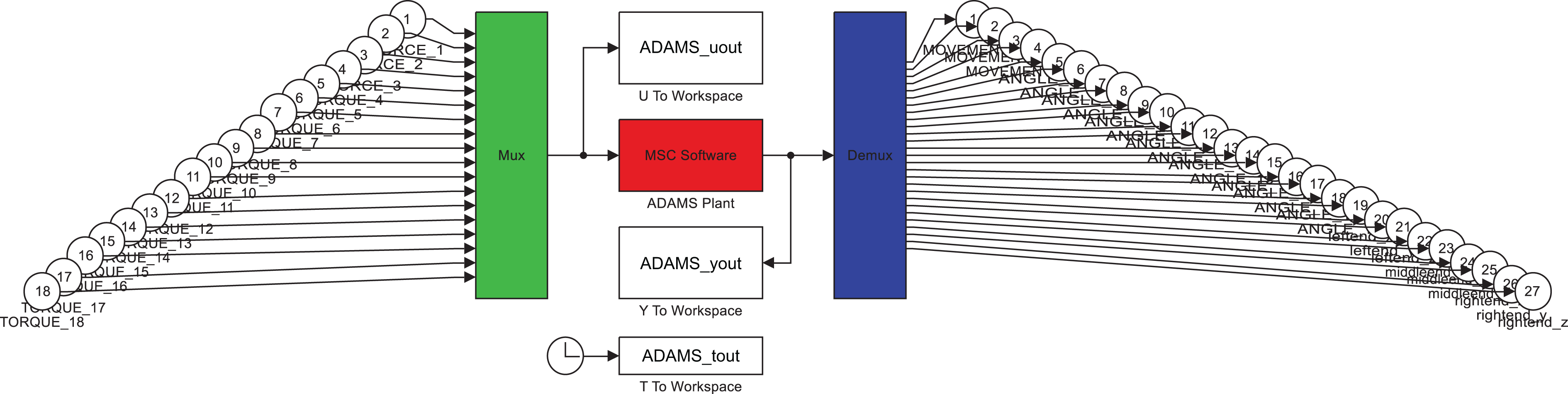
Input and output in ADAMS.
The controller in MATLAB generates joints control signals with the help of PID tuner. PID tuner uses the response time or bandwidth and phase margin sliders to tune the controller’s performance to our requirements. Increasing performance typically decreases robustness and vice versa. Tuning PID controllers meets these objectives by tuning the PID gains to achieve a good balance between performance and robustness. The optimized parameters Kp , Ti , Td of the inner layer were obtained as shown in Table 5, under the initial values are 0.01 and 0.6 in response time and transient behavior combining the constraint parameters of control system in Table 6. Then the control signals are transferred to ADAMS where the T-shape structure welding robot moving characteristics could be clearly observed to realize the ADAMS/Simulink co-simulation finally. Robot system simulation in Simulink is shown in Figure 10. The parameters generated by ADAMS are introduced to Simulink where the coordination controller based on “hierarchical planning” is established. The control block diagram of robot system in Simulink is shown in Figure 11.
The optimal values of the parameters of the PID controllers.

The performance parameters of the control system.


System simulation in Simulink.

Control block diagram of robot system in Simulink.
Effectiveness of the coordination control
The basic parameters are set as follows. Simulation interval is 0.005s. The simulation time of the whole dual-beam laser welding process is 26.193s. The simulation platform is MATLAB 2019a on a desktop workstation with Intel Xeon 3.70 GHz processor. From the control block, time series that represent the time-evolution of the dynamic dual-beam laser welding process could be obtained to calculate the end effectors error in data that is sampled over discrete time intervals. Set

Results of the error of manipulators’ end effectors: (a) error of middle manipulators along X-axis, (b) error of middle manipulators along Y-axis, (c) error of middle manipulators along Z-axis, (d) error of left manipulators along X-axis, (e) error of left manipulators along Y-axis, (f) error of left manipulators along Z-axis, (g) error of right manipulators along X-axis, (h) error of right manipulators along Y-axis, and (i) error of right manipulators along Z-axis.

Results of the steady-state error of manipulators’ end effectors: (a) error of middle manipulators along X-axis, (b) error of middle manipulators along Y-axis, (c) error of middle manipulators along Z-axis, (d) error of left manipulators along X-axis, (e) error of left manipulators along Y-axis, (f) error of left manipulators along Z-axis, (g) error of right manipulators along X-axis, (h) error of right manipulators along Y-axis, and (i) error of right manipulators along Z-axis.
According to Figure 12, the error of end effectors of T-shape structure welding robot with multiple manipulators converges to a small value for the process of dual-beam laser welding, which verifies that the coordination control strategy proposed is feasible. The results of error of the end effectors in X, Y, Z direction show that the controller based on the error allocation satisfies the system rapidity and makes the overshoot less, improving the stability of the robot.
The results of the steady-state error of T-shape structure welding robot end effectors are shown in Figure 13. It is observed from Figure 13(d) to (i) that the controller based on the error allocation reduces both the steady-state error of left and right welding manipulator end effectors in X, Y, Z direction respectively, which improves the accuracy of the welding process. Although the steady-state error of the middle manipulator increases slightly according to Figure 13(a) to (c), the magnitude of the steady-state error of the middle manipulator is one less than the other two manipulators. In other words, the steady-state error remains basically unchanged.
The peak and setting time values of the error change curve are extracted from Figure 12, and the steady-state error values at 25s are extracted from Figure 13, which are shown in Table 7. “Setting time” and “Setting time*” are the time required for the response to reach and stay within the specified range (4
The performance evaluation of robot end effectors.

Conclusion
According to the process of dual-beam laser welding, the T-shape structure welding robot end effectors error is analyzed based on robot structure and kinematics. The influence of welding robot’s each joint motion on end effectors error is obtained, which is helpful to adjust the end effectors error with guidance and accurate control of robot during the dual-beam laser welding process. A double closed-loop control strategy on the basis of hierarchical planning is provided to ensure the overall accuracy requirements of T-shape structure welding robot. The control algorithm was tested and verified with experiments using MATLAB–ADAMS Simulink co-simulation. The results of the end effectors error of T-shape structure welding robot with multiple manipulators are obtained. Finally, experimental results were analyzed and it is concluded that the coordination control based on error allocation has higher stability and better accuracy, especially for the left and right welding manipulators with higher accuracy requirements compared to the middle pressing manipulator. Since the coordination control method designed in this article is based on the error allocation model, the coordination control method performs better in the control of the robot with large difference of joint influence on the end effector.
The future work will be focused on the optimal algorithms using the robot with multiple manipulators controller, the observation and effect of the disturbance on the robot with multiple manipulators will also be further studied.
Footnotes
Declaration of conflicting interests
The author(s) declared no potential conflicts of interest with respect to the research, authorship, and/or publication of this article.
Funding
The author(s) disclosed receipt of the following financial support for the research, authorship, and/or publication of this article: This work was supported by National Key R&D Program of China (2018YFB1700902).