
Abstract
Tunnel boring machine (TBM) is a large-scale tunnel engineering equipment, which has unparalleled advantages in safety and work efficiency. The cutter is subjected to complex and variable random impact loads, resulting in damage to bearings, cutter rings, and cutter shafts. Therefore, based on the discrete element simulation platform and experiment, this paper established the cutter rock simulation model based on the experimental data, and analyzed the rock breaking process, cutter load magnitude, and variation law. The research results show that when the cutter pole diameter decreases from 200 mm, 100 mm, and 0 mm in sequence, the rolling force increases accordingly, and the maximum increase of the rolling force is 56%. Meanwhile the lateral force decreases and the maximum average decrease value is 26%. Moreover, the rolling force showed a downward trend with the increase of the cutter spacing. When the cutter spacing is increased from 80 mm to 120 mm, the average rolling force decreases by 51%, and the maximum value rises slightly, increasing by 2%. And, the lateral force tends to increase, with an increase of 17% and the maximum lateral force value increase was 29%. The results can provide load input reference for TBM cutter layout, cutterhead structure design, and performance evaluation.
Introduction
Tunnel boring machine (TBM), it is a new, advanced large-scale high-end tunnel engineering equipment, which uses a rotary cutter to excavate and break the surrounding rock in the cave to form a complete rock tunnel. TBM integrates excavation, gravel collection, and safety support. TBM is widely used in water conservancy and hydro-power, municipal administration, high-speed railway tunnels, and national defense. It has the advantages of fast, high quality, safety, economy, and environmental protection. At present, the key core components of TBM mainly rely on imports. Domestic manufacturers provide geological information to foreign manufacturers and design by foreign companies. They only manufactures and assembles certain structural components in China. So, there is an urgent need to absorb and digest its key core technologies, break foreign monopolies, and achieve domestic production. Cutters are the executing part of the TBM machine, which can withstand varying soil and rock loads, and the working conditions are complex and changeable.1,2 The novelty of this paper is that the wire cutting experiment and simulation of the cutter are carried out at the same time, and the bonding bond properties of the particles in the discrete element simulation carried out are corrected by the actual cutter linear cutting data. After determining the particle model, use this model to perform different forms of cutter rotation simulation experiments in EDEM. The force of the TBM cutter under different parameters is analyzed, and the corresponding data is obtained. Thus, this research can provide a theoretical basis for the design of cutter structure.
Nowadays, the demand for tunnel boring machines (TBM) is increasing in engineering departments all over the world. As can be known, research on the rock breaking mechanism and load change rules of TBM cutters have attracted extensive attention from scholars at home and abroad. Ates et al. 3 studied the statistical relationship between the design parameters of the roadheader, revealed the theoretical concept of the relationship between TBM diameter and installed thrust, and discussed the relationship between the rated torque capacity of the cutterhead, total weight, maximum speed of the cutterhead, and the number of disc cutters. Because of the rapid development of numerical simulation technology. Jiang et al. 4 and Xia 5 used the finite element and discrete element methods to establish the cutter, geotechnical model, simulate the intrusion process of the cutter on the rock, and study the destruction of the rock mass and the three-way force loading state of the cutter. This numerical simulation test saved time, manpower, and test costs. Zhu et al., 6 Tan et al. 7 studied the crushing effect and crushing of disc cutter by comparing the changing rules of various parameters such as different loads, cutter spacing, blade angle, and cutting depth efficiency, and analyzed the quantity, characteristics, and energy consumption law of crushed stone in the cutting process. Wu et al. 8 studied the effects of different cutters and cutter combinations on rock-breaking effect and rock-breaking rules through slewing experiments. Vibration problems during TBM work are also the focus of people’s attention. Abnormal vibration causes a series of problems such as damage to mechanical systems. Chen et al., 9 Yang et al., 10 and Zou et al.11–13 studied the dynamic characteristics of TBM during the work process, focusing on the discussion of vibration source, influencing parameters, dynamic modeling, and vibration isolation methods, which provided very important theoretical reference. For the structural design and vibration reduction optimization of the cutterhead system. Liu, 14 Hasanpour et al.,15,16 and Afrasiabi et al.17–23 were devoted to studying various performance parameters that affect the work of TBM, such as rock parameters and machine parameters to establish prediction theoretical models of TBM performance. Methods such as “penalty factor” and “pso-ann hybrid model” were proposed to estimate the performance of TBM, which enriched the theoretical model of intelligent prediction. Zhou et al. 24 studied the interaction between the surrounding rock and the roadheader under the action of high stress and high water pressure to establish a hydraulic coupling model, used to monitor the displacement and pore pressure around the tunnel in different directions throughout the construction period to evaluate the tunnel construction scope of influence. Haeri et al.25,26 studied the interaction mechanism of TBM disc cutter with rock through experiments and improved numerical simulation methods, and predicted the path and direction of rock crack propagation based on fracture mechanics. At the same time, the cutter cutting efficiency under different parameters of the cutter and the corrosive condition are studied. Zhou and Zhai 27 studied in detail the composition of the cutter disc torque working in mixed geology, deduced the contact force formula between the cutter and the rock face, and obtained that the cutting torque caused by the disc cutter was the main component of the disc torque. This study provided an important theoretical basis for the design of the disc and cutter. Yang et al. 28 analyzed the trajectory of the TBM disc cutter and established a three-dimensional model of the disc cutter rock breaking process. The three-dimensional model of the rock breaking mechanism was used to predict the mixing cutting force in the case of soil. With the rapid development of underground space development, conventional circular tunnel boring machines can no longer fully meet the requirements of underground space development in terms of cross-section and space utilization rate. For example, Li 29 introduced the technical characteristics of non-circular TBM and development status, researched the advantages of non-circular tunnel boring machine in construction progress and space utilization. Hasanpour et al. 30 conducted a three-dimensional simulation of the machine and the surrounding ground using finite difference code FLAC3D by studying actual cases, such as the severe shield clogging incident during the excavation of the Uluabat tunnel, and numerically simulated the three sections along the tunnel. The analysis effectively evaluated the impact of adverse geological environment on TBM performance. Wang et al. 31 and Paltrinieri and Sandrone 32 focused on the study of tool wear and evolution during shield excavation through theory and experiment, laying a theoretical foundation for optimizing cutter parameters and extending the service life of TBM cutters.
In summary, domestic and foreign scholars have done a lot of research on the structural characteristics, performance evaluation and influencing parameters of TBM, but most of them analyzed by means of theoretical analysis or numerical simulation. There has been controversy about the rock breaking mechanism and load characteristics of the cutter. However, it is difficult to establish a rock constitutive model that conforms to the actual working conditions by numerical simulation methods. Also it is difficult to simulate the fracture phenomenon when the rock is broken by the finite element method. On the other hand, the load analysis of cutters is mostly based on experimental data, which is difficult to get close to the actual working state of TBM. Because cutter rock breaking is a complicated change process, and cutter bearing capacity is a complex and irregular impact load, discrete element methods can be used to better simulate the actual cutter rock breaking process and reproduce the rock breaking conditions. The premise is to construct a rock constitutive model close to the actual working conditions. To this end, this paper combines the indoor cutter linear cutting experiment and discrete element method to study the rock breaking process, load, and influencing parameters of TBM cutter. The cutter wire cutting experimental data is used to calibrate the rock constitutive model parameters, and the rock property data is used to redefine the operation mode of the cutter. Simultaneously, the rock cutting simulation of rotary cutting with different cutters was carried out to study the stress characteristics of the cutters under different parameters and to determine the optimization plan. For example, according to the research conclusions of this paper, the rolling force and lateral force of the cutter are related to the size of the cutter spacing. As we all know, the center cutter receives more rolling force, while the side cutter receives more lateral force. Researchers can appropriately reduce the distance between the center cutters or the side cutters based on the results of this study. Designing reasonable cutter forms at different positions of the cutterhead can reduce the force and prolong the service life of the cutter. This research can provide technical reference for the structure design and parameter matching of cutter.
The cutter is prone to damage under rock squeezing, which will have a greater impact on the construction progress and construction quality. At present, scholars have used advanced numerical simulation technology to propose various prediction models. But, cutter forms and construction scenarios are more complex and diverse, and the force of the cutter is also more complicated. The correct prediction of the force of the cutter is particularly important for the design and life of the cutter. Therefore, it is necessary to make a more in-depth study on the mechanism of the cutter and rock.
Cutter loading and wire cutting experiment
Cutter structure
During the TBM driving process, the cutter first comes into contact with the rock, and the stress conditions are complex and changeable. Most of the tunnel excavation projects used today are disc-shaped cutters. The schematic diagram of the structure is shown in Figure 1. The cutter is mainly composed of a cutter shaft, a cutter body, a cutter ring, a bearing, and several seals.

Structure diagram of disk cutter.
In the components of disc cutter, the rock breaking work is mainly completed by the cutter ring. In other words, the properties of the cutter ring directly affect the rock breaking effect, the life of the entire cutter, and even the progress of the project. Thus, the loads research on the cutter ring is still the top priority for TBM rock breaking efficiency.
Rock breaking load of cutter
The loads of the cutter have always been the focus of domestic and foreign scholars in the study of TBM. The actual loads during the excavation are extremely complicated. For this reason, the research on the force of the cutter needs to be analyzed together with the actual construction situation and the properties of the excavated rock. The generally force form of cutter is shown in Figure 2.
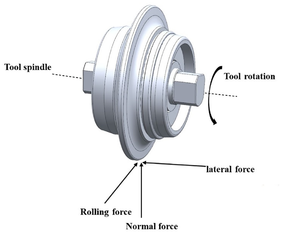
Force analysis of cutter.
When TBM is actually working, the force of the cutter can be decomposed into rolling force, normal force, and lateral force. Among them, the normal force is the reaction force caused by the cutter intruding into the rock. It is mainly provided by the propulsion system of the cutterhead, and the direction is along the axis of the contact point between the cutterhead and the rock. For another, the rolling force is the reaction force from the rock when the cutter rotates to break the rock, and the direction provided by the torque of the cutterhead is the same as the rotation direction of the cutter. Beyond that, the lateral force is the force on the edge of the cutter, which mainly comes from the squeezing of rock caused by the rotation of the cutterhead after the cutter intrudes into the rock mass, and the direction is parallel to the axis of the cutter.
The force situation when the cutter breaks the rock is relatively clear. However, due to the uncertainty of rock structure, it often occurs that the cutter is unstressed because the Cutter has not cut into the rock, or the contact area is too large or too small due to sudden structural change. Therefore, the numerical simulation analysis of the cutter under different working conditions is very helpful to improve the life and working efficiency of the cutter.
Rock cutting experiment
Experimental scheme
The cutter wire cutting test and the discrete element wire cutting simulation were carried out respectively, and the force change data of the cutter obtained by the two methods were compared. Based on the test data, the discrete element model is constantly modified and the cutter operating mode is changed. Then simulate the modified model to keep the simulation data close to the test data. When the gap between the simulation data and the test data is within a certain reasonable interval, use this discrete element model as the final model for subsequent rotation simulation tests.
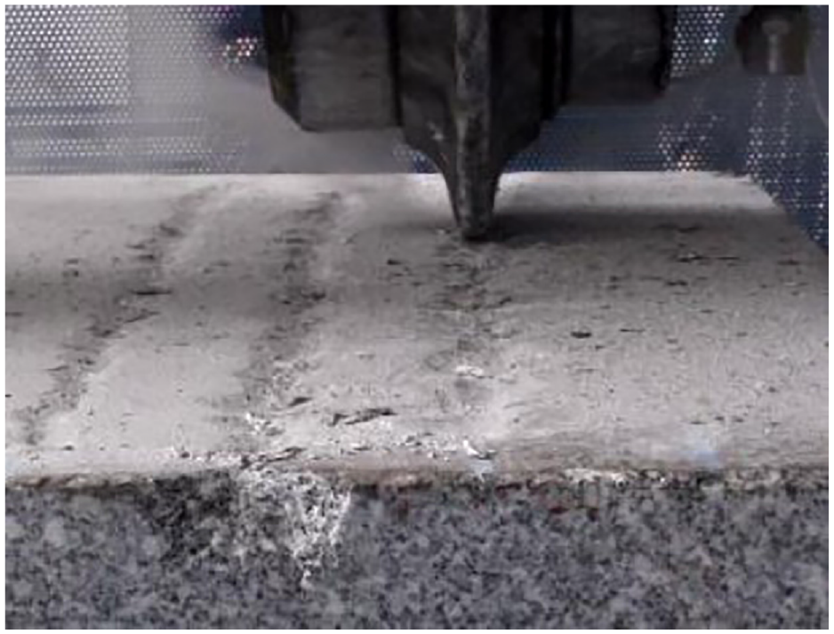
The actual experiment is carried out on the cutter wire cutting experimental table. The structure is shown in Figure 3. The size of the experimental table is 5 m × 3.2 m × 3.5 m, and the load carrying capacity is 60 t. The rock used in the experiment is granite, which is common in actual surrounding rocks, and its mechanical properties are shown in Table 1.

Experimental bench of cutter wire cutting.
Rock mechanics parameter table.

The experimental scheme is that under the same cutter spacing, the cutter wire cutting experiment with different filling amounts is performed in a constant thrust manner. The cutter spacing is 80 mm. The experimental process is shown in Figure 4.
Experimental process.
Experimental results
The experimental results include rock fragmentation of the cutter at different penetrations and the force of the cutter. This article aims to establish a discrete element model of rock based on the cutter force obtained from the experiment, so this section only introduces the force of the cutter. The experimental data of cutter wire cutting is shown in Figure 5. Because the plan is a linear cutting experiment, the cutter itself has no rotary motion, so the lateral force is not considered.

Experimental data of cutter wire cutting.
Numerical simulation of cutter linear rock breaking
Discrete element model for cutter rock breaking
The Hertz-Mindlin contact model is the default particle contact model of the software. When the particle model used in the simulation needs to resist the destruction of external forces, it can be added with bonding properties. This bonding property is based on the Hertz-Mindlin bond contact model.in the EDEM software. This model can prevent the relative movement of tangential and normal directions between the particles by generating the mutual bonding force between the particles. When the external force received by the particles reaches the maximum normal or tangential stress, this bonding will occur accordingly. After the destruction of the particles, the Hertz-Mindlin contact model is used in a discrete manner to perform interaction calculations.
The bonding model is widely used in the simulation of hard bonding materials such as simulated concrete, rock, clay, etc. The bonding model is shown in Figure 6. Wherein, the resultant force of the bond is generated at the center of the interface where the two spheres of two or more particle models are in contact with each other. The particles are bonded at a certain set time t, before The particle interaction is generated by the default Hertz-Mindlin contact model.

Hertz-Mindlin bonding contact model.
In order to simulate the actual state of the rock breaking of the TBM cutter, it is necessary to establish a model of rock and TBM cutter equivalent to the actual project. In EDEM, only simple geometric models can be established, and complex geometric models cannot be established. Generally, other three-dimensional modeling software is used to complete the complex geometric model, and then import it. In this paper, the three-dimensional model of the cutter ring is established through Pro/E, and it is saved as IGES, STEP, PROE, and other formats that can be imported into EDEM. The size parameters of the cutter model established in this paper are shown in Table 2.
Cutter model dimensions.

The equal-size cutter ring model based on Pro/E is shown in Figure 7.

Model of cutter ring.
Due to the huge amount of calculation involved in EDEM simulation, the rock model used in the experiment is simplified in the numerical simulation, and the compromise between the smallest amount of calculation and the most complete rock properties is selected to improve the solution efficiency, so online 600 × 300 × 100 rock block model was selected in the numerical simulation of linear cutting.
In order to ensure the stability of the rock model, after the particles naturally accumulate and fill the tank, model should be allowed to stand for a period of time until the speed of all the particles becomes low enough, and then the bond should be added. In order to ensure that the size of the stone slab meets the requirements, the solution range should be reduced to specify the size after accumulation and overflow. The process is shown in Figure 8 and the completed rock model is composed of 17,756 particles.
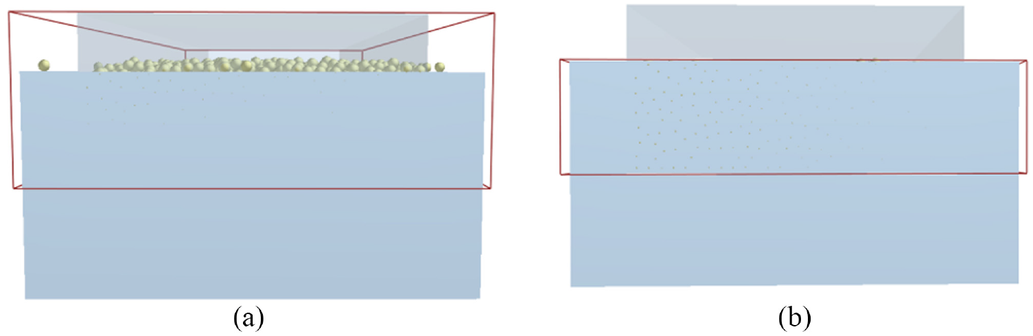
Rock model size setting: (a) before narrowing the scope and (b) after narrowing the scope.
In order to simulate the linear cutting process of the cutter, it is necessary to set the penetration speed and rotation speed of the cutter, and add motion to the EDEM software. The specific parameters are shown in Table 3. 33
Cutter motion parameters.

This section mainly uses the first two data to determine the movement mode of the cutter. Before the cutter cuts the rock, the bond key needs to be added first. The properties and effects of the added bond keys are shown in Figure 9. Among the Hertz-Mindlin bonding contact model, the parameter setting of the bond between the particles is the most difficult point in this subject. The parameter setting of cement key is shown in Figure 9(a), which relates to the positive stiffness per unit area, shear stiffness per unit area, critical normal stress, critical shear stress and cement radius of the cement key. These five values exist inside the cement, and cannot be calculated from the rock properties. That is, the only way is to use the actual experimental data to simulate multiple times in discrete element software and change its value, so that the experimental data is as close as possible to the actual experimental data to indirectly obtain the rock properties.

Bonding bond between particles: (a) viscous bond properties setting and (b) effect picture of viscous bond.
In the movement mode of the cutter, rolling, and oblique downward linear movement are combined to simulate the process of penetration from 0 mm to 10 mm. The motion settings are shown in Figure 10.

Setting of cutter motion: (a) linear motion setting and (b) rotary motion setting.
At this point, all preparations for wire cutting are completed, and calibration of cement parameters based on fuzzy boundary method is started. Due to the excessive number of simulations, the final result is directly released here. The rolling force and vertical force of the cutter finally extracted are shown in Figure 11.

Vertical force and rolling force of the cutter: (a) rolling force (kN) and (b) vertical force (kN).
Both of the two broken line graphs suddenly increased after 0.17 s. According to the numerical simulation data of the wire cutting, it was inconsistent with the actual data. By comparing with other data, it can be concluded that the vertical force is between 55.00 kN and 227.00 kN, with an average value of 141.23 kN. Moreover, the rolling force is between 11.00 kN and 56.00 kN, with an average value of 38.86 kN. (Because the direction of the force is opposite to the coordinate axis, it is negative in the chart.)
Figure 12 is a comparison between the cutter wire cutting experiment and numerical simulation data. In the above analysis, the average penetration is 5.35 mm, the average rolling force is 55.43 kN, and the average vertical force is 166.36 kN in Table 4. By comparing the change trend and mean value of simulation data and experimental data, the error is within 20% and the change trend is the same, which proves the rationality of the numerical model. Therefore, the rock model constitutive at this time is used to carry out the subsequent cutter rotary cutting simulation.

Line graph of cutter force: (a) vertical force and (b) rolling force.
Simulation and experimental force values.

The viscous bond damage and stress of the cutter in operation are shown in Figure 13.
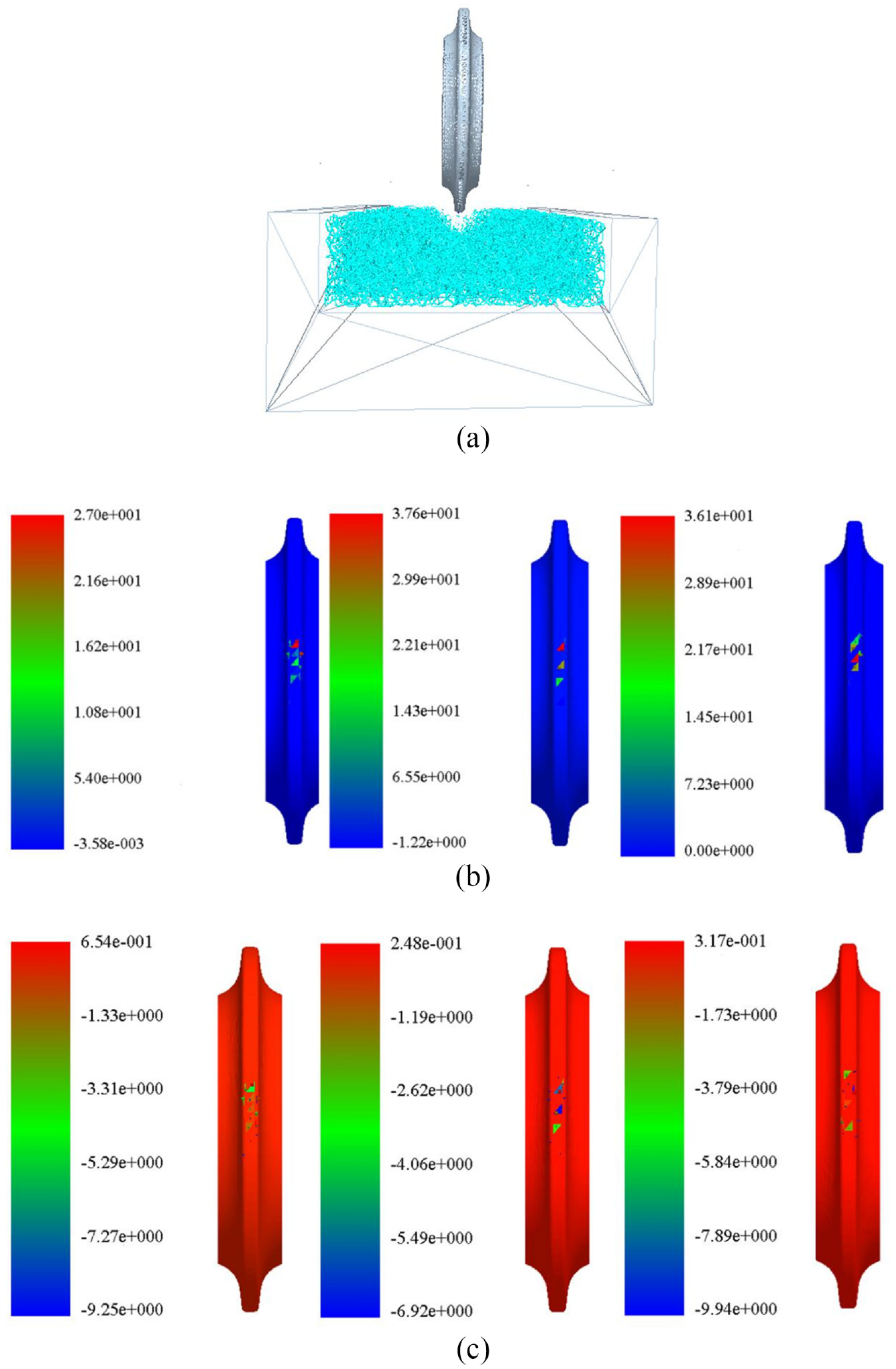
Bond damage and stress: (a) the destruction of the bond, (b) vertical force of penetration of 3 mm, 5 mm, and 6 mm, and (c) rolling force of 3 mm, 5 mm, and 6 mm.
According to the analysis of the actual experimental results in section II, the data in this group is basically consistent with the theoretical and actual values, so in the subsequent numerical simulation, this group of bonding data is used for simulation analysis.
Numerical simulation of cutter rotation rock breaking and influence analysis of parameters
Numerical simulation of rock breaking with different cutter radius
In order to analyze the lateral force of the cutter, it is necessary to simulate and analyze the rotary rock breaking of the cutter. By changing the center distance of the cutter, the degree of influence of different center distances on the cutter was studied. In order to simulate the rotary cutting rock breaking of the cutter, it is necessary to change the model of the rock groove used. Considering the efficiency of the model solution, the Φ250 mm and 30 mm high rock model is used for equivalence. The rock stacking forming process is shown in Figure 14(a). The treated model contains a total of 15,441 rock particles. After all particles are stabilized, the viscous bond is generated. The generated viscous bond is shown in Figure 14(b).

Rock trough model: (a) rock forming process and (b) viscous bond established.
This simulation involves three kinds of motion, one is the rotation of the cutterhead, the second is the rotation of the cutter, and the third is the feed of the cutterhead. In order to conveniently measure the rolling force and tangential force of the tool, the rotation and feed motion of the tool are added to the cutter ring, and then the reverse rotation motion is added to the stone groove to replace the rotation of the cutterhead. The movement is added as shown in Figure 15.

Add movement: (a) add linear motion, (b) add rotary motion, and (c) adding the rotary motion of the stone trough.
This paper intends to carry out three sets of slewing rock breaking simulations, and the cutter pole diameter is reduced from 200 mm to 0 mm, each time by 100 mm. The parameter setting of the tool movement has been proposed in the previous section, and the article will not repeat it here.
The failure of the three-time bond is shown in Figure 16.

Destruction of viscous bonds: (a) 200 mm bond bond damage, (b) 100 mm bond bond damage, and (c) 0 mm bond bond damage.
The vertical forces with the three groups of cutters are shown in in Figure 17.

Vertical force curve of cutter: (a) vertical force when cutter pole diameter is 200 mm (kN), (b) vertical force when cutter pole diameter is 100 mm (kN), and (c) vertical force when cutter pole diameter is 0 mm (kN).
Through the vertical comparison of the three groups of vertical forces, the vertical force does not change monotonously. When the cutter pole diameter is 100 mm, the average vertical force is the largest, and as the penetration increases, the overall vertical force tends to increase.
Due to the large number of numerical simulation data, the absolute values of the lateral force and rolling force of the three groups of cutters are compared in the same graph respectively, and the comparison of the three groups of simulated rolling forces is shown in Figure 18.
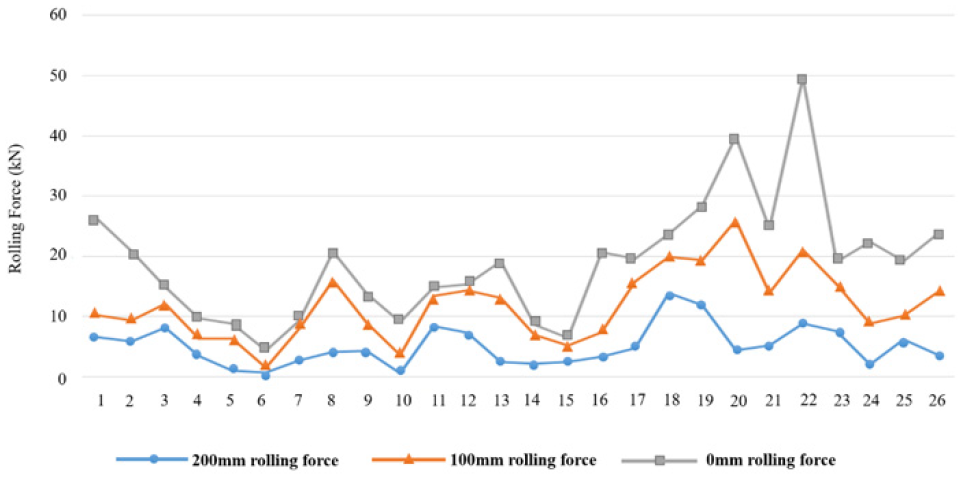
Rolling force curves for different cutter pole diameters.
It can be seen from the comparison of the rolling force that as the cutter pole diameter decreases, the rolling force tends to increase. When the cutter pole diameter is 200 mm, the average rolling force is 5.02 kN and the maximum value is 13.84 kN. When the cutter pole diameter is 100 mm, the average rolling force is 6.73 kN, and the maximum value is 21.59 kN. When the cutter pole diameter is 0 mm, the average rolling force is 7.15 kN and the maximum value is 28.62 kN. Beyond that, the cutter pole diameter was reduced from 200 mm to 100 mm, the average rolling force increased by 1.71 kN, an increase of 23%, the maximum value increased by 7.75 kN, an increase of 56%. When the pole diameter is reduced from 100 mm to 0 mm, the average rolling force increases by 0.42 kN, an increase of 6%, and the maximum value increases by 7.03 kN, an increase of 32%. It can be seen that, as the pole diameter of the cutter is reduced, the rolling force received by the cutter is increasing, but the increase is gradually smaller.
Then, the lateral force curve is processed according to the same method, and the comparison after processing is shown in Figure 19.

The lateral force curve of different cutter pole diameters.
From the comparison of the lateral force curve, it can be seen that as the blade spacing increases, the lateral force on the cutter increases. When the blade spacing is 80 mm, the average lateral force on the cutter is 5.06 kN, and the maximum value is 15.26 kN. When the blade spacing is 120 mm, the average lateral force on the cutter is 6.05 kN, and the maximum value is 19.65 kN. In addition, the average distance between the blades increased from 80 mm to 120 mm, increasing by 1.00 kN, or 17%. The maximum value increased by 4.39 kN, an increase of 29%.
From the comparison of the upper and lower figures, it can be seen that during the rock breaking process of the cutter, the vertical force received when rolling is much greater than the lateral force and rolling force. (The rolling force and lateral force are displayed as negative numbers because two forces are opposite to the direction of the software coordinate axis.)
Rotary rock breaking numerical simulation of double-edged cutter
In order to carry out the research in this section, two types of double-edged cutter models with different pitches were designed, with a cutter pitch of 80 mm and 120 mm, respectively.
The three-dimensional modeling of the cutter is shown in Figure 20.

Three-dimensional model of two double-edged cutters (a) 80 mm pitch cutter, (b) 120 mm pitch cutter.
Numerical simulation of rock breaking with double-edged cutters with blade spacing of 80 mm and 120 mm. The damage of the viscous bond is shown in Figure 21.
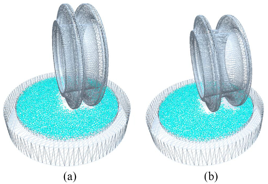
The destruction of the bond: (a) 80 mm viscous bond damage and (b) 120 mm viscous bond damage.
This section mainly focuses on the rolling and lateral forces that are greatly affected by the blade spacing. Judging from the damage of the cemented rock by the cutter, the damage to the rock mass by the cutter with a spacing of 80 mm is relatively concentrated. The cutter with 120 mm cutter spacing can form a penetration when breaking the rock, so that the whole piece of rock is exfoliated. The absolute value of the rolling force and lateral force curves of the two cutters are shown in Figure 22.
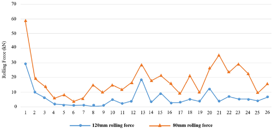
Rolling force curve of different cutter spacing values.
It can be seen from the comparison of the rolling force curve that when the cutter spacing increases, the rolling force decreases. When the blade spacing is 80 mm, the rolling force on the cutter has an average value of 12.08 kN and a maximum value of 28.99 kN. When the blade spacing is 120 mm, the average rolling force on the cutter is 5.82 kN, and the maximum value is 29.67 kN. Besides, the average distance between the blades increased from 80 mm to 120 mm, showing a downward trend, decreasing by 6.26 kN, a decrease of 51% and the maximum value rises slightly, increasing by 2%.
Use the same method to process the lateral force curve. The results obtained are shown in Figure 23.

Lateral force curve with different cutter spacing values.
From the comparison of the lateral force curve, it can be seen that as the blade spacing increases, the lateral force on the cutter increases. When the blade spacing is 80 mm, the average lateral force on the cutter is 5.06 kN, and the maximum value is 15.26 kN. When the blade spacing is 120 mm, the average lateral force on the cutter is 6.07 kN, and the maximum value is 19.65 kN. In addition, the average distance between the blades increased from 80 mm to 120 mm, increasing by 1.00 kN, or 17% and the maximum value increased by 4.39 kN, an increase of 29%.
Conclusion
In this paper, based on the discrete element software EDEM, single-edged cutter, double-edged cutter, and cemented particle rock model for numerical simulation are established. Carried out the numerical simulation of single cutter wire cutting, rotary cutting, and double-edged cutter rotary cutting to guide the design and achieve the purpose of increasing the life of TBM cutter. The following are the main research contents and conclusions of this article:
The EDEM rock parameter calibration method was studied, and it was decided to use the fuzzy boundary method to perform multiple numerical simulations of cutter line cutting, combined with actual data to complete the calibration of rock properties, and obtained rock particles for numerical simulation Bond bond properties. In general, the conclusion is that with the increase of penetration, the vertical force and rolling force bearing tend to increase.
A numerical simulation of rock breaking with a single cutter was carried out and it was found that the rolling force increased with the decrease of the cutter pole diameter. The cutter pole diameter was reduced from 200 mm to 100 mm. Among them, the average rolling force increased by 1.71 kN, an increase of 23%, the maximum value increased by 7.75 kN, an increase of 56%. When the pole diameter is reduced from 100 mm to 0 mm, the average rolling force increases by 0.42 kN, an increase of 6%, and the maximum value increases by 7.03 kN, an increase of 32%. Meanwhile, the average increase decreased by 17%, and the maximum increase decreased by 24%. It is inferred that the rolling force due to the change in linear velocity increases, but the magnitude decreases. Next, the lateral force decreases as the cutter pole diameter decreases. The cutter pole diameter is reduced from 200 mm to 100 mm, the average value of the lateral force is reduced by 0.29 kN, a decrease of 8%, and the maximum value is reduced by 0.95 kN, a decrease of 5%.Finally,when the pole diameter is reduced from 100 mm to 0 mm, the average lateral force is reduced by 0.05 kN, a decrease of 2%, the decrease is 6%, the maximum value is reduced by 7.03 kN, and the decrease is 26% and the decrease has increased by 21%. Therefore, it is considered that the change of the cutter pole diameter has no obvious influence on the lateral force of the cutter.
Simulate the rock cutting process of the double-edged cutter with different cutter spacings. It is found that a large cutter spacing can improve the rock breaking efficiency of the cutter, and the rolling force shows a downward trend. The cutter spacing value increased from 80 mm to 120 mm. wherein, the average rolling force decreased by 6.26 kN, a decrease of 51% and the maximum value rises slightly, increasing by 2%. Moreover, the lateral force tends to increase, with an average increase of 1.00 kN, or a 17% increase and the maximum value increased by 4.39 kN, an increase of 29%. Therefore, the design of the double-edged cutter should be combined with the allowable stress of the cutter material in the positive and tangential directions to determine a reasonable cutter spacing.
In this paper, the discrete element method was used to initially simulate the rock breaking process of the TBM cutter, but the different surrounding rock material conditions were not studied, and the cutter was assumed to be a rigid material. Accordingly, the research results need to be verified by the actual TBM tunneling project. In addition, there are fewer types of TBM cutters involved in this paper, the change of cutter spacing, and the number of blades are insufficient. The conclusion drawn may be affected by errors. The next work focuses on studying the influence of different surrounding rock parameters and combined surrounding rock working conditions on the rock breaking law and load characteristics of the cutter, and coupled with the finite element method to introduce the properties of the flexible body cutter, considering the cutter wear and other conditions. This model can be applied to similar granite cutting simulations. In addition, when TBM is actually tunneling, the results of this paper can also be used to correctly predict the force of the cutter, so as to modify the layout and design of cutter. Last but not the least, we can also study the crushing efficiency of TBM cutters under different parameters based on the number of broken bonds.
Footnotes
Handling Editor: James Baldwin
Declaration of conflicting interests
The author(s) declared no potential conflicts of interest with respect to the research, authorship, and/or publication of this article.
Funding
The author(s) disclosed receipt of the following financial support for the research, authorship, and/or publication of this article: This work is financially supported by the China Postdoctoral Science Foundation funded project [No.2020 M671956]; the Natural Science Foundation of Fujian Province, China [No.2017J01675]; and the Scientific Research Foundation of Fujian University of Technology [No.GY-Z160048].