
Abstract
The concept of tunnel boring machine (TBM) disc cutter rock breaking coupled with high-pressure water jets has been proposed to overcome the difficulties that occur when TBMs encounter extremely hard rocks. Thus, to meet actual engineering requirements for the TBM construction of tunnels as part of the Wan’anxi water diversion project in Longyan City (Fujian Province, China), experiments were conducted on high-pressure water jet-assisted TBM disc cutter rock breaking. By varying kerf depth and width under different water jet parameters and performing disc cutter rock breaking tests on rock surfaces with no kerf, single kerf, and double kerfs, the effects of different kerf depths on the disc cutter rock breaking process, load, and efficiency were examined. The test results showed that high-pressure water jets can generate the regular kerfs required for the coupled disc cutter rock breaking of granite. Employing the coupled rock breaking method also resulted in a decrease in specific energy and an approximately 40% decrease in the normal force of the disc cutter, thereby significantly improving rock breaking efficiency. These results provide key technical parameters for the design and manufacture of high-pressure water jet-assisted rock-breaking TBMs and serves as a reference for similar processes.
Introduction
Tunnel boring machines (TBMs) are tunnel engineering construction machines that use disc cutters on a rotating disc cutter to cut rocks by extrusion and shearing, acting on the entire cross-section of the tunnel at any given time. Under the circumstance of good geological condition and well-prepared construction, 1 they have excavation rates that are generally 3- to 10-fold higher than those of conventional drilling and blasting methods. As a large-scale high-tech construction equipment designed for the excavation of underground passages, TBMs have the advantages of fast excavation, high efficiency, and safety. Additionally, they are economical, environmentally friendly, reduce labor intensity, and play an important role in the construction of underground passages.
When a TBM encounters hard rocks with good integrity during the tunnel boring process, it is usually extremely difficult for its disc cutter to penetrate the rock. Under such circumstances, the disc cutter can only be forced into the rock after several rotations; thus, the boring efficiency is reduced. Additionally, such hard rocks severely wear out the disc cutter, making its frequent replacement necessary, thereby limiting the construction efficiency of the TBM. According to engineering statistics on the Qinling Tunnel of the Xikang Railway1,2 and the Hanjiang River–Weihe River water conveyance tunnel in the Shanxi Province, 3 the saturated uniaxial compressive strength of a rock and the rock mass integrity have a significant effect on tunnel boring efficiency. When the saturated uniaxial compressive strength of a rock is above 200 MPa, the boring speed will be less than 0.6 m/h, and the drill footage per month will only be approximately 100 m. In the TBM-excavated section of the water conveyance tunnel in the Lanzhou water source construction project, where the strata lithology is predominantly quartz schist, quartz diorite, and granite with an average saturated uniaxial compressive strength of 101.8 MPa, a total of 409 disc cutters were replaced during the process of boring the first 3602 m of the tunnel, that is, an average of 0.11 disc cutters/m. 4 In the southern section of the Qinling Tunnel of the Hanjiang River–Weihe River water transfer project, where the strata lithology is granite, the saturated uniaxial compressive strength and integrity coefficient of the country rock were 166.7 MPa, and 0.7, respectively. During this project, a total of 1626 disc cutters were used during an excavation of 1891 m, that is, an average of 0.86 disc cutters/m.5,6 Considering these two engineering examples, it is evident that a 64% increase in the saturated uniaxial compressive strength of a rock from 101.8 to 166.7 MPa results in an approximately seven fold increase in tool wear out rate.
Several attempts have been made to identify measures that facilitate rock breaking and improve boring efficiency to resolve difficulties with boring when TBMs encounter extremely hard rocks. In the 1960s and 1970s, the National Science Foundation of the U.S. funded a large-scale research project, with the objective of identifying efficient cutting methods for rock breaking. In this study, 25 new methods, including the application of electric sparks, lasers, flames, plasma, and high-pressure water jets, were proposed and tested before the high-pressure water jet method was identified as the most feasible and effective method. 7 In 1972, the Railway Technical Research Institute of Japan proposed a rock breaking method in which high-pressure water jet-assisted disc cutters were integrated into a hard-rock breaking TBM with a diameter of 3.8 m. The laboratory results showed the possibility of a 2.5-fold increase in boring speed. 8 In 1979, the Mining Research Company of West Germany and the Wirth Company collaborated to manufacture a rock boring machine with a diameter of 2.65 m, equipped with 14 double-edged disc cutters, a cone-shaped center cutter, and 100 high-pressure water nozzles. With the jet pressure at 400 MPa, the tests results showed that the overall thrust of the boring machine could be reduced by 30%, and there was a ∼32% to 43% decrease in its power consumption. 9 The American Institute of Mining analyzed jet parameters during rock cutting and suggested, based on their findings, that the jet pressure must exceed 210 MPa to effectively cut rocks such as granite and that the optimal pressure and target distance ranges should be ∼280 to 350 MPa and 25.4∼50.8 mm, respectively. 10 However, due to various limitations such as the easy clogging of the nozzles and problems associated with sealing, the abovementioned experimental results have not been applied practically.
In recent years, research on high-pressure water jet-assisted rock breaking has been primarily focused on the fields of mining and oil field drilling. High-pressure water jets are used to assist the mechanical attempts to improve the efficiency of rock breaking. Through several experimental analyses, studies have been conducted on water jet characteristics, tool parameters, and water jet positions relative to mechanical tools.11–16
This paper presents experimental research on TBM disc cutter rock breaking coupled with high-pressure water jets with a focus on the hard granite strata at the site of the Wan’anxi water diversion project in Longyan City (Fujian Province, China). By choosing different water jet pressures, nozzle diameters, and nozzle moving speeds, the effects of high-pressure water jets on the depth and width of granite kerfs were investigated. Additionally, the effects of different kerf depths on the rock breaking process, load, and efficiency under different conditions – including no kerf, single kerf, and double kerfs – were compared and analyzed using linear cutting tests. This was done to identify key technical parameters for the design and manufacture of high-pressure water jet-assisted rock-breaking TBMs.
Project background
The Wan’anxi water diversion project in Longyan City (Fujian Province, China) was designed to meet medium- and long-term water supply needs in the main urban area of Longyan. The project draws water from the tail channel of the Daguan hydropower station in Liancheng County and conveys it through water conveyance tunnels and pipes to the water treatment plant in the north wing of the planned central urban area. The project primarily includes water intake structures, water conveyance tunnels and pipes, and structures at intersections along the line. The water conveyance line has a total length of 33.79 km, of which 14.936 km represents the length of the tunnel sections that require the open TBM method for their construction. The excavation cross-section is a circle with a diameter of 3.83 m and the maximum buried depth of the tunnel is 931 m.
The strata lithology of the TBM constructed sections of the water conveyance tunnel primarily consist of biotite-granite, granodiorite, quartz sandstone, and quartz conglomerate, as shown in Figure 1. The county rock types mainly include type II and III rocks, with integrated rock mass, high rock strength, high contents of hard minerals, such as quartz and feldspars, as well as high abrasiveness.

Geological cross-section of Wan’anxi water diversion project in Longyan.
According to geological survey data, the maximum saturated uniaxial compressive strength of biotite-granite, granodiorite, quartz conglomerate, and quartz sandstone are approximately 226, 120, 137, and 129 MPa, respectively, and their quartz contents are approximately 20 to 35; 20 to 35; 25 to 40 up to 81%, and 25 to 36 up to 68%, respectively. Such high-strength and high-abrasive rocks stand as a serious drawback to TBM construction.
Rock breaking mechanisms
The rock breaking TBM disc cutter coupled with the high-pressure water jet is an improvement of conventional rock breaking processes. Firstly, the high-pressure water jet is used to cut kerfs into the rock, and thereafter, the position of the disc cutter relative to the kerf is adjusted to achieve efficient rock breaking. Based on the differences in the relative positions of the disc cutter and the kerf, this method can be divided into two kinds, that is, single-kerf and double-kerf coupled rock breaking methods, and their detailed layouts are described in section “Test parameters.”
With the single-kerf coupled rock breaking method, the disc cutter and high-pressure water nozzles were positioned along the same track. Thus, the disc cutter directly acts on the kerf cut in by the high-pressure water jet, and to increase the speed of disc cutter penetration and improve rock breaking efficiency, rock failure is brought about by direct disc cutter shearing, and not by disc cutter extrusion. With the double-kerf coupled rock breaking method, the disc cutter was placed midway between the two kerfs on the rock surface, and during the rock cutting process, the kerfs on both sides of the disc cutter served as free surfaces, making the stress distribution in the rock different from the stress distribution on an infinite plane. Therefore, the capacity of the rock to resist breakage was weakened, and it became easier to generate rock fragmentation. Simultaneously, the splitting and sputtering of the high-pressure water jet generates irregular cracks in the rock, which also accelerate the initiation and extension of cracks during the disc cutter rock breaking process. In order to explain the rock break mechanics more clearly, the following Figure 2 is given.

Rock break mechanisms: (a) single joint coupled rock fracture, (b) double joint coupled rock fracture.
High-pressure water jet rock breaking experiments
Experimental ideas
In this study, a high-pressure water jet cutting test platform independently developed by the Nanjing Dadi Water Cutter Company (Figure 3) was used, and test granite samples were obtained from the Longyan water diversion project site. The experiment was mainly designed based on current water-jet rock breaking theories in combination with reliable and stable industrial equipment, and high-pressure water jets with different parameters were used to cut the rock samples. By collecting data on the performance indicators of the cutting tests, the key parameters that clearly showed an effect on the rock breaking performance, such as the appropriate jet pressure, nozzle diameter, and nozzle moving speed were identified and investigated. This provided technical support for application of the rock breaking technology coupled with a high-pressure water jet to the Longyan water diversion project.
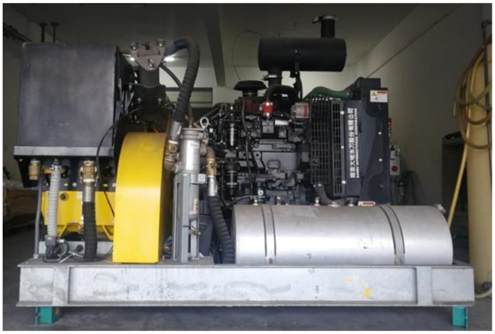
Equipment used for high-pressure water jet cutting tests.
Several parameters affect the rock breaking performance of high-pressure water jet-assisted TBMs, and depending on the rock type these parameters can be selected to ensure optimal performance. 10 The objective of the experiments conducted in this study was to determine the optimal parameters required to ensure a high performance of the high-pressure water jet system. This objective was attained by analyzing the rock breaking performance of high-pressure water jets under different parameter conditions. The rock breaking performance indicators included kerf depth and width; during the tests, the flow rate and the power of a single nozzle under different water jet pressures and nozzle diameters were recorded to provide a basis for the final equipment parameter selection.
Test parameters
High-pressure water jet-rock cutting is a complicated process, and several factors affect the rock cutting performance of the high-pressure water jet. Thus, while conducting studies on the application of water jets to cut objects as well as for other purposes, it is necessary to identify the most suitable and controllable water jet parameters.
From the perspective of guiding the design and manufacture of the TBM for the Longyan water diversion project, these tests were based on existing reliable equipment conditions, and included several factors that have relatively significant effects on the applicability of the test results. Because of the complexity of TBM machines, there are variety of limitation when combining high-pressure water jet system with it; machines of abrasive jets, cavitating jets, and pulse jets are more complex and difficult to construct, so only pure water is used in the high-pressure water breaking test.
The control parameters of high-pressure water jet mainly include kinetic energies such as jet pressure, flow rate, velocity, power and recoil force. The flow rate is equal to the jet exit velocity times the cross-section area of nozzle, and the jet exit velocity is positively correlated with jet pressure. Jet power is a function of jet pressure and nozzle size, that is, jet power is proportional to the square of diameter nozzle and 2/3 of KPA.17,18 Therefore, it is considered that the jet pressure and diameter nozzle can reflect the influence of jet flow and kinetic energy on jet characteristics. Additionally, the water jet pressure is the direct control parameter of high-pressure pump equipment while diameter nozzle is the direct selection of equipment. So as to ensure a better guidance for future TBM equipment contrail and selection, jet pressure and diameter nozzle are selected as control parameters in this test. Consequently, the test parameters selected for the experiments included: jet pressure (p), nozzle diameter (d), and nozzle moving speed (v). The minimum jet pressure was set at 140 MPa, which is slightly lower than the compressive strength of the granite sample, and the maximum value was set at 380 MPa, which is slightly higher than the maximum stable output pressure (320 MPa) of existing ultra-high-pressure pump units and water supply facilities that can be integrated into TBMs. The nozzle diameter was chosen from the four common sizes, and the nozzle moving speed was selected based on the linear speed at the position of nozzle on the TBM disc cutter. The specific values of the test parameters are listed in Table 1.
Test parameters.

The target distance represents the distance between the outlet of the water jet nozzle and the working face of the rock to be cut. In order to protect the high-pressure water nozzle equipment and prevent clogging, the nozzles on the TBM disc cutter were designed to be 40 mm away from the rock surface and the water jet was sprayed vertically, that is, a uniform target distance of 40 mm was used and the spraying angle was set at 90°.
The rock sample, which had a determined uniaxial compressive strength of 143 MPa, was granite from the Longyan water diversion project site, and its size was 500 × 300 × 200 mm.
Test procedure
During the tests, a vertical water jet was used, and the target distance was set at 40 mm. The test variables included: jet pressure (p), nozzle diameter (d), and nozzle moving speed (v). Based on the parameter ranges stated in the previous section, a total of 87 sets of rock cutting tests are conducted, and 435 pairs of kerf depth and width data on the rock cutting effect of the high-pressure water jet were collected. A typical rock surface before and after cutting is shown in Figure 4.

Rock surfaces: (a) before cutting, (b) after cutting with high-pressure water jet.
Test results and analysis
Variation in kerf depth with water jet pressure
The variation in kerf depth with the pressure from the high-pressure water jet is shown in Figure 5. The rock breaking capacity of the high-pressure water jet increased as the jet pressure increased. The tests results showed that the kerf deepened gradually as the jet pressure increased gradually, and the relationship between these two parameters was basically linear.

Variation of kerf depth with jet pressure: (a) d = 0.74 mm, (b) d = 0.97 mm.
Variation of kerf depth with nozzle moving speed
The variation of kerf depth with the nozzle moving speed of the high-pressure water jet is shown in Figure 6, which shows that the rock breaking capacity of the high-pressure water jet increased as the nozzle moving speed decreased, that is, when the jet moving speed was reduced, there was a significant improvement in the cutting performance of the water jet.
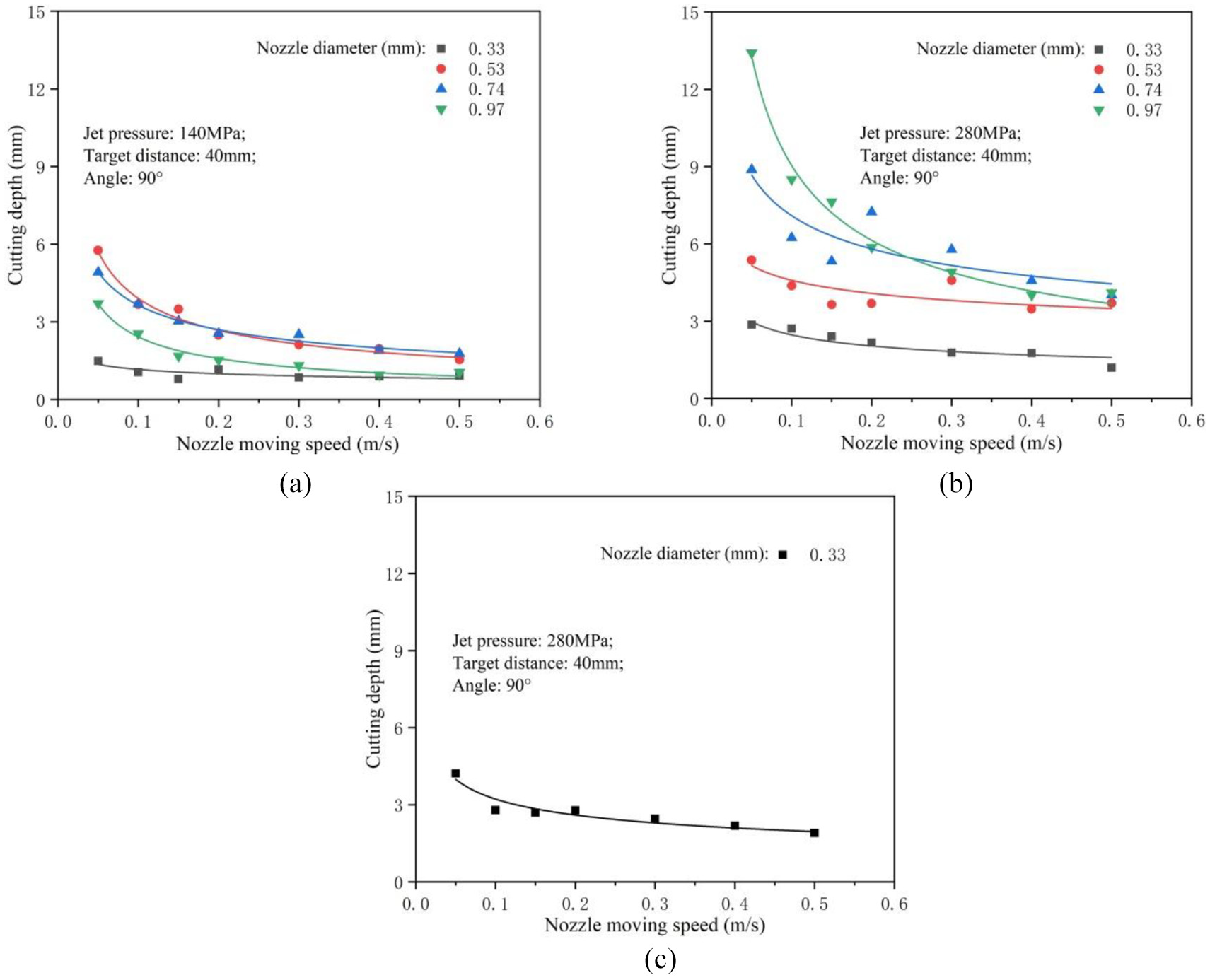
Variation of kerf depth with nozzle moving speed: (a) p = 140 MPa, (b) p = 280 MPa, and (c) p = 380 MPa.
Variation of kerf depth with nozzle diameter
Figure 7, which illustrates the variation of the kerf depth with the nozzle diameter of the high-pressure water jet shows that there was an increase in the rock breaking capacity of the high-pressure water jet as the nozzle diameter increased, indicating that at a constant jet pressure, increasing the nozzle diameter results in an increase in the energy content of the water jet. Thus, rock breaking becomes easier as the cutting depth and width increase. Furthermore, in this study the nozzle diameter was the only key parameter with a direct effect on the width of jet cutting kerf.

Variation of kerf: (a) depth and (b) width with nozzle diameter at p = 140 MPa. Variation of kerf: (c) depth and (d) width with nozzle diameter at p = 280 MPa.
The results obtained show that even though the rock cutting performance of the water jet changes with different combinations of jet pressure, nozzle moving speed, and nozzle diameter, changing these parameters resulted only in small variations in kerf depth and width; thus, the spalling and fragmentation of large rock pieces could not occur. This indicated that under current high-pressure water jet rock breaking conditions, independent rock breaking cannot be achieved with respect to relatively hard granite. Thus, the high-pressure water jet can only be used to complement TBM rock breaking.
Coupled rock breaking experiments
Experimental ideas
In these experiments, a multi-functional mechanical rock breaking test platform independently developed by Beijing University of Technology 19 was used (Figure 8), and granite samples were used for the high-pressure water jet-assisted TBM disc cutter linear rock breaking tests. Before the tests, kerfs were pre-cut into the rock samples by using the high pressure water jet device in laboratory to simulate the rock conditions observed after breakage with high-pressure water jets. The rock breaking process was then performed by moving the disc cutter along the kerf or midway between two kerfs. The load parameters of the tool during the disc cutter rock breaking process were collected, and the spalled rock fragments were gathered to conduct a comparative analysis as a function of the load conditions and the quantity of rocks broken via disc cutter rock breaking without pre-cut kerfs. The impact of the kerf depth and position on the load and efficiency of the disc cutter rock breaking process was also investigated.

Multi-functional mechanical rock breaking test platform.
Test parameters
The rock-breaking disc cutter used in this experiment was a common 17-inch disc-shaped TBM disc cutter with a blade width of 17 mm. The penetration and cutting speed of the disc cutter were set at 4 mm and 20 mm/s, respectively. The triaxial forces (normal, rolling, and side forces) of the disc cutter during the tests were measured at a frequency of 100 Hz. After each test, the rock surface was photographed, and the rock debris gathered. Three different categories of tests were performed as follows:
The rock breaking test was performed with the disc cutter and with no kerfs on the rock surface, that is, the whole rock surface was cut directly with the disc cutter penetration set at 4 mm;
The rock breaking tests were performed with the disc cutter and a single kerf on the rock surface as shown in Figure 9(a). The width of all kerfs was 2 mm and different kerf depths (2, 4, and 6 mm) were used. The rock breaking position of the disc cutter was along the pre-cut kerfs;
The rock breaking tests were performed with the disc cutter and with double kerfs on the rock surface as shown in Figure 9(b). All the kerfs had a width of 2 mm and different kerf depths (2, 4, and 6 mm) were used. The distance between the two kerfs was 81 mm (the common disc cutter spacing) and the rock breaking position of the disc cutter was midway between the two kerfs.

Schematic representation of rock breaking tests performed using the disc cutter with: (a) single kerf and (b) double kerfs.
The size of the granite rock samples was 1000 × 1000 × 600 mm, and their determined uniaxial compressive strength was 172 MPa.
Test procedure
First, after loading the rock sample into the test chamber, a confining pressure of 0.5 MPa was applied to it. This was to prevent it from shaking or slipping off during the rock breaking process. Thereafter, the rock surface was pre-cut according to the test requirements. To ensure that uniform and flat cutting tracks were left on the rock surfaces, the cutting penetration was less than 0.5 mm. A small cutting machine was used to cut the rock surface along the center line of the track, and the cutting depth error was controlled within ±0.2 mm. Finally, the no-kerf, single-kerf (Figure 10(a)), and double-kerf (Figure 10(b)) disc cutter rock breaking tests were performed with a hop penetration of 4 mm. To eliminate the edge effect and interference between disc cutters, the distance between the disc cutter cutting position and the edge of the rock or the adjacent disc cutter was >200 mm. The triaxial forces of the disc cutter were recorded during the tests, and the rock debris was gathered after the tests.

Disc cutter positions during rock breaking tests with: (a) single or (b) double kerfs.
Test results
No-kerf disc cutter rock breaking test
When the no-kerf rock was cut using the disc cutter, no rock fragments were generated from the rock surface; just the cut groove was visible on the rock surface as shown in Figure 11(a). The normal rock breaking force was extremely large, approximately 500 kN. It was basically stable and did not fluctuate (Figure 11(b)). This test was a simulation of the common TBM rock breaking condition, and it served as a reference for the comparison of the subsequent rock breaking tests on rock surfaces with kerfs.
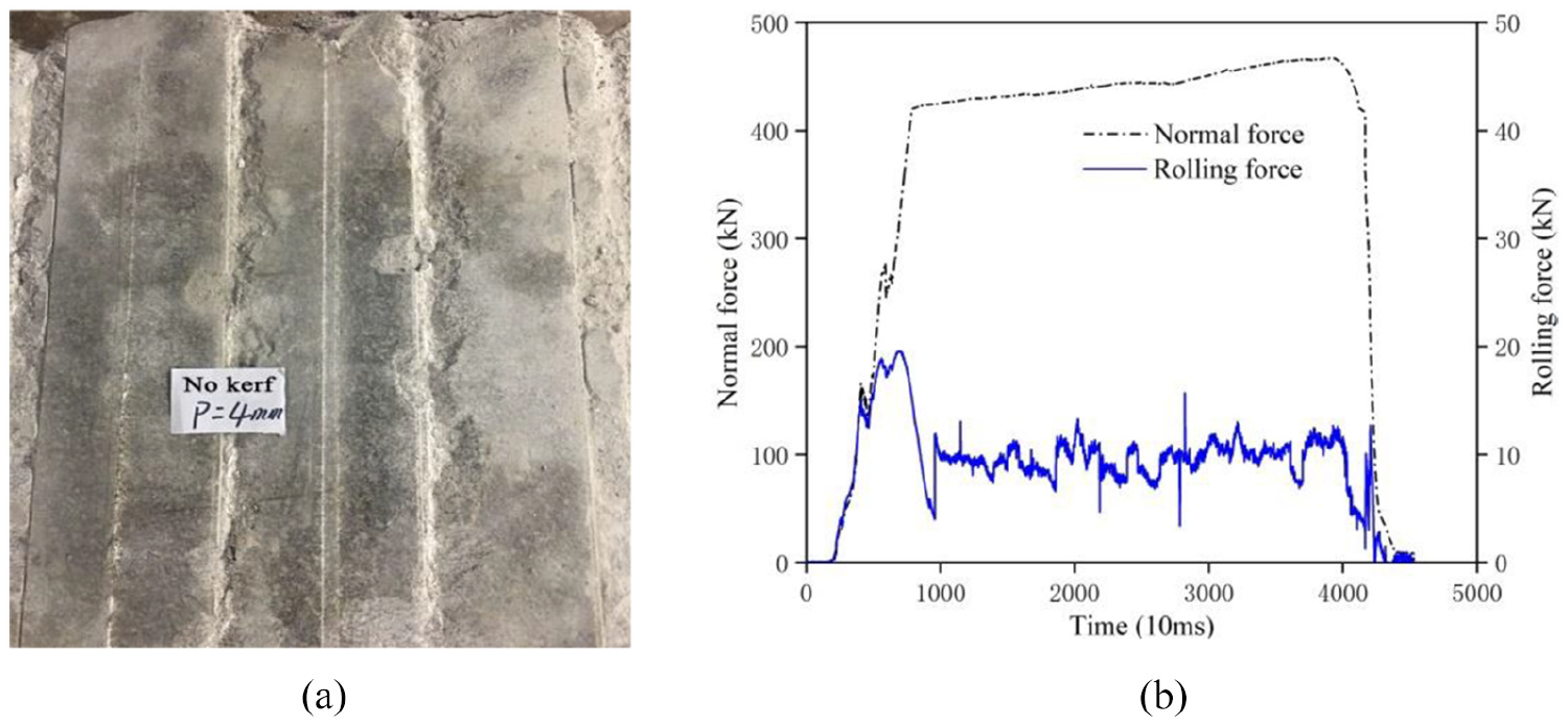
(a) Rock surface after the no-kerf disc cutter rock breaking process, (b) variation in the normal and rolling forces of the disc cutter during the no-kerf test.
Single-kerf disc cutter rock breaking tests
Single-kerf rock breaking test with a kerf depth of 2 mm
With a kerf depth of 2 mm, it was clearly observed that during the disc cutter rock breaking process, the rock surfaces on both sides of the kerf moved closer toward the kerf under the disc cutter extrusion, and a small number of grains burst out from the two sides of the disc cutter (Figure 12(a)). Several rock powder particles and grains accumulated along each side of the kerf, and small pieces of fragments were locally generated. After cleaning the rock debris, it was found that relatively deep cutting grooves appeared where the fragments had been locally generated, and the groove was deeper than the kerf. As shown in Figure 12(b), during the rock breaking process, the normal force fluctuated slightly, and its instantaneous maximum peak value was approximately 420 kN. During the second half of the rock breaking process, there was a sudden drop in the normal force, while there was a sharp increase in the rolling force in the areas where the fragments were generated. This was mainly due to the vacancy beneath the disc cutter after the rock fragments burst out. The stress of the disc cutter was quickly released, decreasing the normal force. After the generation of the rock fragments, the grooves that appeared on the rock surface made disc cutter rolling more difficult; thus, there was increase in the magnitude of the rolling forces.

(a) Rock surface after the single-kerf disc cutter rock breaking process, (b) variation in the normal and rolling forces during the single-kerf rock disc cutter breaking process (single kerf depth 2 mm).
Single-kerf rock breaking test with a kerf depth of 4 mm
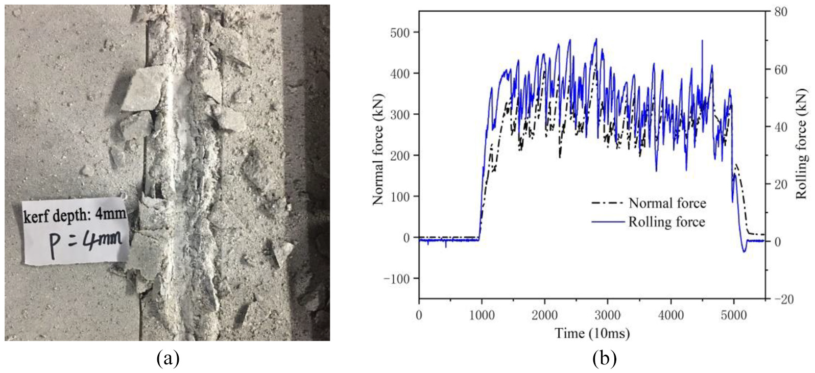
With a kerf depth of 4 mm, the disc cutter vibrated during the rock breaking process and the sound was relatively loud; under the disc cutter extrusion, the rock surfaces on both sides of the kerf moved toward to the kerf and a large quantity of rock powder particles and grains were generated beneath the disc cutter as shown in Figure 13(a). Some rock fragments burst from both sides of the disc cutter and large pieces of fragments were occasionally generated locally. After cleaning the debris from the rock surface, deep and wide cutting grooves were observed along the kerf; occasionally, some grooves formed on each side of the cutting disc cutter owing to the spalling of rock pieces. The grooves deepened as the kerf depth increased. During the rock breaking process, normal and rolling forces fluctuated rapidly; however, the amplitude of their fluctuations was small and the instantaneous maximum peak value of the normal force was approximately 400 kN (Figure 13(b)).
(a) Rock surface with single kerf after disc cutter rock breaking, (b) variation of the normal force and rolling force during the single-kerf disc cutter rock breaking process (single kerf depth = 4 mm).
Single-kerf rock breaking test with a kerf depth of 6 mm
During the rock breaking process, a kerf depth of 6 mm resulted in a smaller disc cutter vibration and quieter sound relative to the 4-mm kerf depth test. Under disc cutter extrusion, the rock surfaces on both sides of the kerf also moved toward the middle, and a large quantity of rock powder particles and grains were generated beneath the disc cutter, and some rock fragments burst out from both sides of the disc cutter (Figure 14(a)). Occasionally, fragments were locally generated; however, they were small-sized. After cleaning the rock debris, it is found that the degree of rock breaking was relatively low, and the depth and width of the cutting groove along the kerf were small. Additionally, as shown in Figure 14(b), there were rapid fluctuations in the normal and rolling forces; however, the amplitude of the fluctuations was small. The instantaneous maximum peak value of the normal force was approximately 350 kN.

(a) Rock surface with single kerf after disc cutter rock breaking, (b) variation of the normal and rolling forces during the single-kerf disc cutter rock breaking process (single kerf depth = 6 mm).
Double-kerf disc cutter rock breaking tests
Double-kerf rock breaking test with a kerf depth of 2 mm
With a kerf depth of 2 mm, the rock was cut midway between the two kerfs, resulting in a deep cutting groove on the rock surface. Rock debris was rarely produced, and only a small amount of fine rock powder particles were generated (Figure 15(a)). As shown in Figure 15(b), the normal force was extremely large, its variation was negligible, and its fluctuation were very minute. Its instantaneous maximum peak value was approximately 470 kN, which is similar to that observed with the no-kerf rock breaking process.

(a) Rock surface with double kerfs after disc cutter rock breaking, (b) variation in the normal and rolling forces during double-kerf disc cutter rock breaking (double kerf depth = 2 mm).
Double-kerf rock breaking test with a kerf depth 4 mm
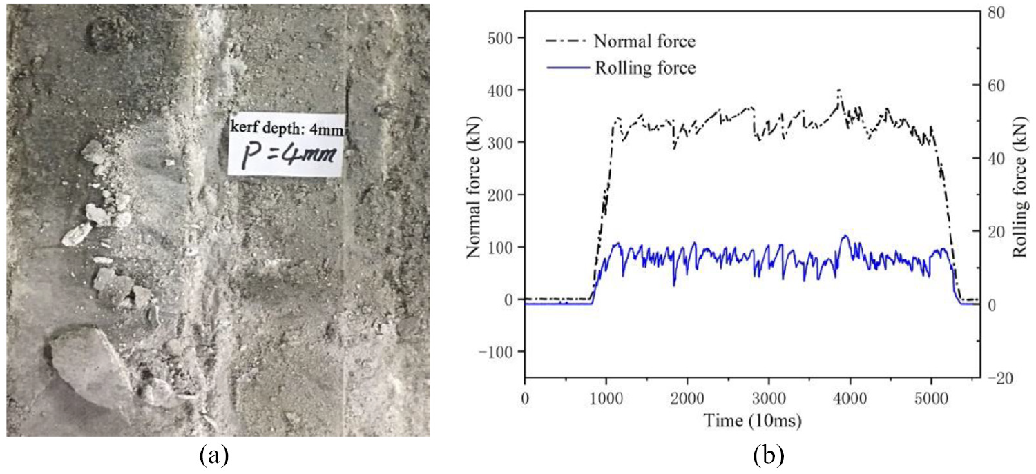
With a kerf depth of 4 mm, the disc cutter vibrated significantly during the rock breaking process, and the rock breaking sound was loud. As shown in Figure 16(a), under disc cutter extrusion, the rock surface was severely broken under the disc cutter extrusion, rock fragments often burst out from both sides of the disc cutter, and obvious dust clouds were observed. Significant amounts of rock powder particles and grains were generated beneath the disc cutter, and many rock fragments with width approximately equal to 30 mm were generated along the sides of the disc cutter rolling direction. It was clearly observed that the rock breakage occurred between the two kerfs, and no rock debris was generated on the outer sides of the kerfs, that is during the rock breaking process, the cracks propagated to the kerfs and stopped, and the kerfs had an effect on the propagation of the cracks beneath the disc cutter. After cleaning the rock debris, it was observed that the rock surface between the two kerfs was almost completely spalled off, leaving uneven cutting grooves between the two kerfs, and the grooves were deeper than the kerfs. On both sides of the groove, a small number of unpeeled rock fragments were observed. Additionally, the normal and rolling forces changed rapidly, alternating between a rapid increase and a sharp decrease, showing a leap-frog rock breaking characteristic. The instantaneous maximum peak value of the normal force was approximately 450 kN, and the variations of the normal and rolling forces were consistent (Figure 16(b)).
(a) Rock surface with double kerf after disc cutter rock breaking, (b) variation in the normal and rolling forces during the double-kerf rock breaking process (double kerf depth = 4 mm).
Double-kerf rock breaking test with a kerf depth of 6 mm
With a kerf depth of 6 mm, the rock breaking process was similar to that of the 4 mm double-kerf test. However, a decrease in disc cutter vibration was observed during this rock breaking process; more rock powder particles and debris were generated beneath the disc cutter and the rock fragments obtained were thicker. After cleaning the rock debris, it was observed that the rock surface between the kerfs spalled off more integrally and the cutting grooves were much deeper, as shown in Figure 17(a). Additionally, the normal and rolling forces also changed rapidly, alternating between a rapid increase and a sharp decrease, showing a leap-frog rock breaking characteristic. The instantaneous maximum peak value of the normal force was approximately 400 kN, which is lower than that observed with the 4-mm double-kerf test. The variations of the normal and rolling forces were consistent (Figure 17(b)).

(a) Rock surface with double kerfs after disc cutter rock breaking, (b) variation in the normal and rolling forces during the double-kerf disc cutter rock breaking process (double kerf depth = 6 mm).
Test result analysis
Data processing
During data collection, the mean values of the disc cutter forces (mean normal force Fn, mean rolling force Fr) were obtained; for each of these, the ratios of the area enclosed by the force-time curve and the x-axis to the base line were calculated. The specific rock breaking energy (SE), an important indicator of rock breaking efficiency, was calculated according to equation (1) as follows:
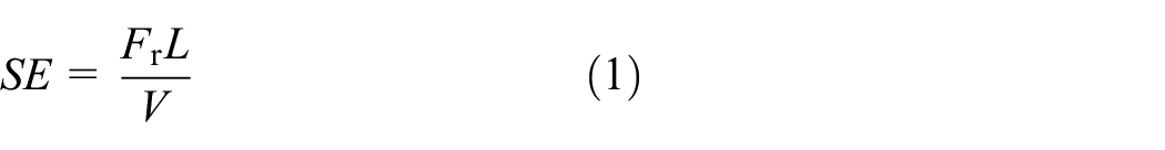
where SE (MJ/m3) represents the specific energy, Fr (kN), represents the mean rolling force, L (m) represents the length of the rock cut out by the disc cutter, and V (m3) represents the volume of the rock fragments generated during the rock breaking process, that is the ratio of rock mass to rock density, see Table 2.
Summary of test data.

Analysis of mean normal force
Determining the mean normal force facilitates the prediction of the thrust of the TBM disc cutter during the boring process. The variation of the mean normal force with kerf depth is shown in Figure 18(a), which clearly showed that the mean normal force of the disc cutter during the no-kerf rock breaking process was largest when the penetration was 4 mm, and that coupling the rock breaking process with a double-kerf resulted in a decrease in the normal force of the disc cutter by approximately 40%. Regardless of the nature of the kerfs (single or double), there was a rapid decrease in the mean normal force of the disc cutter during the rock breaking process as kerf depth increased; however, the trend of the decline for the two cases was different. During the single-kerf rock breaking process, the mean normal force decreased linearly with increasing kerf depth, and during the double-kerf rock breaking process, it showed a trend of rapid decrease followed by a slow decline. This was primarily because when the disc cutter cuts in on the surface of a single-kerf rock (kerf depth = 2 mm), the kerf is directly below the disc cutter; thus, the rock mass under the disc cutter can deform toward the gap of the single kerf, enabling the disc cutter to penetrate the rock more easily. As kerf depth increases, the ease with which the disc cutter penetrates the rock gradually increases; thus, the mean normal force for the rock breaking process decreases. When the disc cutter was used to cut in on the surface of the double-kerf rock, a kerf small depth (2 mm) made the generation of the free surface effect by the double kerfs impossible; thus, is was extremely difficult for the disc cutter to penetrate the rock, and rock debris could not be generated. Additionally, the rock breaking conditions were similar to those of the same process without kerfs, and the mean normal force was highest during rock breaking. When the kerf depth was increased, the free surface effect was generated by the double kerfs; thus, the disc cutter easily penetrated the rock, and the cracks resulting from the action of the disc cutter during rock breaking effectively extended to the kerfs, causing the rock to break along the kerf edges. The kerf rock breaking-enhancement effect was significant, and under these conditions, the mean normal force of the disc cutter during the rock breaking process was small.
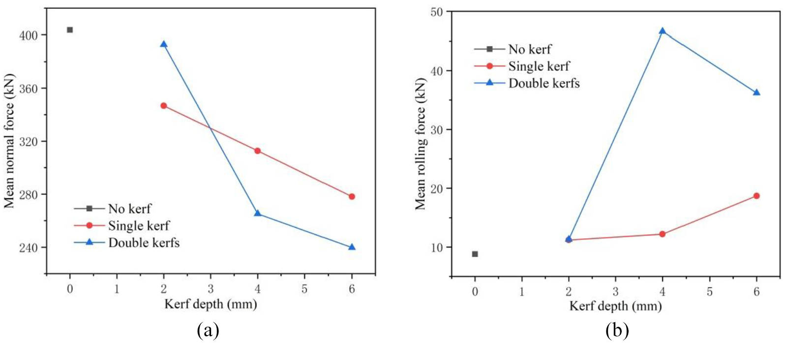
(a) Relationship between mean normal force and kerf depth, (b) relationship between mean rolling force and kerf depth.
Analysis of the mean rolling force
Determining the mean rolling force facilitates the prediction of the torque of the TBM disc cutter during the boring process. The variation of the mean rolling force with kerf depth is shown in Figure 18(b), which shows that the variation of the mean rolling force with kerf depth was different from that of the mean normal force. The mean rolling force was lowest when the no-kerf rock was being broken, and while breaking the single-kerf rock, it gradually increased as kerf depth increased. While breaking the double-kerf rock, it first increased rapidly, and then decreased. These observations primarily resulted from the fact that no rock debris was generated during the no-kerf disc cutter rock breaking process, that is, the rock surface was fairly even, and the resistance to be overcome by the rolling disc cutter was extremely low; thus, the rolling force was low. During the single-kerf disc cutter rock breaking process, an increase in kerf depth resulted in an increase in the generation of rock debris. Additionally, as the rock surface became uneven, the resistance encountered by the rolling disc cutter increased, resulting in an increase in the mean rolling force. When the rock with a double kerf on its surface was broken, the rock breaking process with a kerf depth of 2 mm showed results similar to those of the no-kerf tests. The rock surface was flat, and the rolling force was low. However, when the kerf depth was increased, large quantities of rock debris were generated from the rock surface, and the unevenness of the rock surface was worse than that observed with the single-kerf rock breaking process; thus, there was an increase in the mean rolling force.
Analysis of specific energy
Specific energy represents the energy required to break a unit of a rock. The smaller it is, the lower the energy required to break a unit volume of the rock, and the higher the rock breaking efficiency. The variation of the mass of rock broken with specific energy and kerf depth are shown in Figure 19, which reveals that no rock fragments were generated during the no-kerf and 2-mm double kerf disc cutter rock breaking processes, and the corresponding rock breaking efficiencies were lowest. For single-kerf rock breaking, when the kerf depth was 4 mm, the largest quantity of broken rocks was observed, and the rock breaking efficiency was highest. However, with a single kerf depth of 6 mm, there was a decrease in the quantity of broken rocks produced, resulting in a higher specific energy. This is because the penetration of the disc cutter during these tests was only 4 mm; thus, there was free face below the penetrated disc cutter, and the disc cutter could not fully execute the rock breaking effect. For the double-kerf disc cutter rock breaking process, when the kerf depth was 6 mm, the quantity of broken rocks produced was largest, and the rock breaking efficiency was highest. Additionally, taking all the working conditions into consideration, the 6-mm-deep double-kerf rock breaking process showed the lowest specific energy, that is, the disc cutter reached the highest rock breaking efficiency when the rock surface had 6-mm deep double kerfs.

Variation of the quantity of broken rock generated with: (a) specific rock breaking energy, (b) Kerf depth.
Test conclusions
No-kerf, single-kerf, and double-kerf disc cutter rock breaking tests were performed with a disc cutter penetration of 4 mm. The rock breaking efficiency of the disc cutter was analyzed with respect to the rock breaking phenomena, the load of the rock-breaking disc cutter, and the specific energy. The main conclusions were as follows:
For the single-kerf disc cutter rock breaking tests, the mean normal force decreased linearly as kerf depth increased, while the mean rolling force increased gradually as kerf depth increased. However, when the kerf depth was 4 mm, the degree to which the rock surface was broken and the quantity of broken rock generated were maximum, while the specific rock breaking energy was lowest.
For the double-kerf disc cutter rock breaking tests, the rock breaking-enhancement effect of a kerf depth of 2 mm was insignificant. However, as the kerf depth increased, an increase in the degree to which the rock surface was broken was observed, and the quantity of broken rock debris increased. Additionally, there was a decrease in the normal force during the rock breaking process, which became more intense. However, rock fragmentation only occurred in the area between the two kerfs, that is, no rock fragmentation was observed on the outer sides of each kerf.
Increasing kerf depth enhanced the rock breaking effect of the disc cutter. The deeper the kerf, the easier it was for the disc cutter to penetrate the rock; thus, resulting in a lower mean normal force during the rock breaking process.
When the kerf depth was >2 mm, the quantity of broken rock generated during the double-kerf tests was greater than that generated during the single-kerf tests, and the rock breaking-enhancement effect of the double kerfs was greater than that of the single kerf. Considering all the kerf rock breaking tests, employing 6-mm-deep double kerfs resulted in the smallest specific rock breaking energy, that is, during the double-kerf rock breaking test with the 6-mm deep kerfs, the disc cutter showed the highest rock breaking efficiency.
Conclusion
This research was guided by the actual rock breaking needs of the TBM employed in the Longyan water diversion project. The high-pressure water jet rock breaking technology, which improves the hard rock (e.g. granite) breaking performance of TBMs, was introduced into the conventional TBM rock breaking process. Based on the results of high-pressure water jet rock cutting tests and disc cutter rock breaking tests, the main conclusions arrived in this study are as follows:
To realize effective high-pressure water jet assisted TBM disc cutter rock breaking for both single- and double-kerf rocks, it is required that the depth of the kerf cut in by the high-pressure water jet should be >2 mm.
With the existing jet pressure that can be coupled with the TBM, it is required that the nozzle diameter should be >0.33 mm, and the larger the nozzle diameter, the better the cutting performance.
The higher the jet pressure and the smaller the nozzle moving speed, the better the cutting performance of the high-pressure water jet. Based on its delivery system, including the high-pressure pumping units, rotary joints, and water pipes, a jet pressure in the range of ∼200 to 300 MPa is recommended to ensure the stability and reliability of the water jet system.
With a kerf depth >2 mm, the rock breaking-enhancement effect of the double kerfs was greater than that of the single kerf, and as kerf depth increased, a decrease in the specific energy of the disc cutter rock breaking process was observed, that is, there was a gradual increase in rock breaking efficiency as kerf depth increased. Therefore, properly arranging the disc cutter between the nozzles can achieve better rock breaking performance.
Based on the actual engineering requirements of the Wan’anxi water diversion project in Longyan, this study was mainly focused on investigating the key parameters that affect the rock breaking performance of high-pressure water jets as well as the effects of kerf depth and position on rock breaking performance in a coupled rock breaking process. Based on the test results, the key design parameters of the high-pressure water jet-assisted TBM were determined; thus, providing powerful technical support for the design and manufacture of the first domestically-made high-pressure water jet-assisted rock-breaking TBM. The results of this study also serve as guide and as an importance reference for similar engineering design and equipment manufacturing processes.
Additionally, in this study, pure water and continuous jets were selected for the high-pressure water jet. However, with the popularization of new technologies, including abrasive jets, cavitating jets, and pulse jets, it will be possible to significantly improve the efficiency of the jet operation; thus, further studies in this light are needed.
Footnotes
Handling Editor: James Baldwin
Declaration of conflicting interests
The author(s) declared no potential conflicts of interest with respect to the research, authorship, and/or publication of this article.
Funding
The author(s) disclosed receipt of the following financial support for the research, authorship, and/or publication of this article: This research was funded by the National Natural Science Foundation of China (no. 51569025, no. 51909185, no. 51709124).