
Abstract
Dropper is the key component of in a catenary system and it is prone to fatigue fracture. Dropper stress directly affects the operation safety of high-speed railway. In this paper, a span of dropper in a catenary system is modeled to investigate the effects of contact wire tension on dropper stress. The response equation of contact wire and the theoretical equation of dropper stress are deduced. The initial and boundary conditions of each dropper are determined, and then the stress of each dropper is calculated by the finite difference method using a MATLAB program. The results show that the stress amplitude and the maximum tensile stress of the dropper decrease significantly with the increase of contact wire tension. When the tension is low, the stress changes of dropper near the load location experience three stages: instant rebound, attenuated vibration, and bending compression. However, the attenuation vibration stage disappears when the tension is increased to a certain extent. Therefore, the control of the vibration response of the contact wire can effectively reduce the stress amplitude and the maximum tensile stress of the dropper, so as to improve the working reliability of the dropper.
Introduction
The catenary is mainly composed of contact wire, messenger wire and dropper, which is the key components of a railway electrified system. 1 Dropper is the transmitter of vibration and force between contact wire and messenger wire. It is also the most prone to fatigue fracture in a catenary system. In recent years, with the improvement of train speed, the dropper breaks frequently under the action of alternating stress, which seriously affects the operation safety of high-speed railway. The change of dropper stress is the most essential cause of these situations, therefore it is of great significance to study the change of dropper stress to ensure the safe operation of high-speed railway.
For the study of catenary, Pombo and Ambrosio 2 uses the finite element method and multi-body dynamics method to deal with the dynamics of contact wire and pantograph, and the result provides how to modify pantograph in the design environment. Lopez-Garcia et al.3,4 simplified the pantograph-catenary model, and solved the stiffness change and steady-state distribution of the contact wire under the relaxed state of the catenary, and analyzed the static contact wire tension on both sides of the catenary, and proposed the increase in contact wire tension plays a crucial role in increasing the speed of the train. Park et al.5,6 conducted dynamic analysis on the catenary system based on the finite element method, and proposed that the pantograph-catenary current collection quality determines the maximum speed of the train. Qi et al. 7 studied the fatigue load spectrum and service life evaluation of key components of catenary system under the condition of high-speed train operation. Lee et al.8–10 simulated the influence of contact wire pre relaxation and train speed on the service life of dropper at 400 km/h, and obtained the conclusion that the greater contact wire pre relaxation, the faster train speed and the shorter service life of dropper. Guo et al. 11 studied the fatigue characteristics of Cu-Mg alloy contact wire. The bending fatigue test was carried out to simulate the working conditions of the contact wire, which was used to evaluate the fatigue characteristics of the contact wire of pure copper and Cu-Sn alloy. Combined with the finite element analysis, the relationship between the plastic strain and the fatigue life of the two contact wires was given. Other researchers introduced different pantograph-catenary coupling models and analyzed the dynamic performance of pantograph-catenary.12–16 A lot of efforts have been done in the study of fatigue characteristics of power supply catenary system. These studies promoted a significant increase in fatigue life of catenary system. However, the analysis of dropper stress has been little reported. Understanding dropper stress can help researchers and engineers obtain deeper insight into fatigue characteristics of catenary system.
In order to avoid the fracture of the dropper affecting the safety of high-speed railway, the study of the change of dropper stress induced by contact wire tension is of great significance. In this paper, a span of dropper in a simple chain suspension is modeled to investigate the effects of contact wire tension on dropper stress. This study is helpful in making a detailed understanding of the change of dropper stress. The understanding may be important in designing dropper and controlling contact wire tension.
Differential equation of contact wire motion
Mechanical model of catenary
In this paper, a simple catenary with five droppers is chosen as the research object. Dropper is connected with contact wire, and the vibration of contact wire will directly causes dropper vibration. In the actual working state, the load situation is very complex. It will be very difficult to fully simulate the real situation, which is also a huge challenge. Therefore, in this paper, according to the idea of engineering test simulation, 17 the theoretical vibration equation of contact wire is derived through the excitation of contact wire, so as to obtain the displacement condition of each dropper and determine the initial and boundary value condition of dropper.
In order to facilitate the research in theory, we make some simplifications and assumptions for the system: (1) When the wind load is not considered, the lateral vibration can be ignored. (2) Due to only a span is taken as the research object, the damping effect can be ignored. Therefore, the established mechanical model is shown in Figure 1.

Mechanical model of catenary in a simple chain suspension.
Differential equation
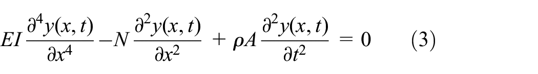
In this paper, Bernoulli-Euler beam element is used to establish the catenary model. For a beam structure, the differential equation of motion is as follows.

where EI is the bending rigidity of the contact wire,
The solution of equation (1) needs to be obtained by boundary conditions. The catenary model established in this paper is shown in Figure 1. There are supports at both ends of the contact wire, therefore, the deflection and bending moment at both ends of the contact wire are zero.

Equation (1) can be solved by the free vibration equation of the beam. The free vibration equation of the beam is as follows.
Since the solution of the equation is separated from time and space, it can be assumed as follows.

Where

Four eigenvalues of equation (5) are obtained by calculation.

The general solution of equation (5) can be expressed as.

Combining the following boundary conditions

By solving, we can get

The frequency equation of the beam is

Thereupon

The modal function is

In order to solve the equation of the contact wire, the mode method is used to set the solution of equation (1).
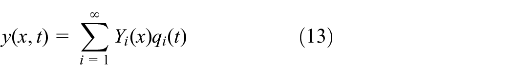
Substituting equation (13) into (1), equation (1) can be transformed into the following equation.

In order to calculate the influence of the j-th mode on the contact wire displacement y(x, t), multiplying both sides of equation (14) by

Due to

Thus, equation (15) can be written as the following.

The following properties of modal function are used.

Equation (17) is transformed into the following equation.

By solving equation (19), we can get

The response of the beam is

Where the constant force F of contact wire excitation is set to 100 N, f is 1 Hz, and
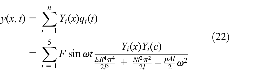
The dynamic response of the structure is mainly caused by the first several low-order modes. Using the mode decomposition method, only a few modes are considered in the calculation, the satisfactory accuracy can be obtained. The influence of the higher order is very small, here, only the first five orders are calculated.
The response equation of contact wire is as follows.
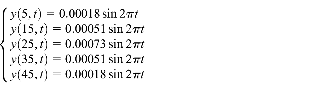
When different tension is applied to the two ends of the contact wire, the vertical displacement of the contact wire will be affected, and the dropper stress will also be affected. In the actual operation of the contact wire, the tension of the contact wire is generally controlled in the range of 15 kN∼30 kN to ensure the safe operation of the electric train. When the load acts on the middle of the contact wire, c = 25. Because the distance between the left support and the dropper I is 5 m, and the distance between the adjacent droppers is 10 m, Therefore, by substituting x = 5, 15, 25, 35, 45 into the above formula, the vertical displacement of the dropper can be obtained.
When the tension is 15 kN, there are as follows.

When the tension is 30 kN, there are as follows.
Calculation of dropper stress
Theoretical equation of stress calculation
The section method is adopted, and the micro element section of the dropper is taken as the research object for stress analysis. The stress diagram of the micro element section of the dropper is shown in Figure 2.
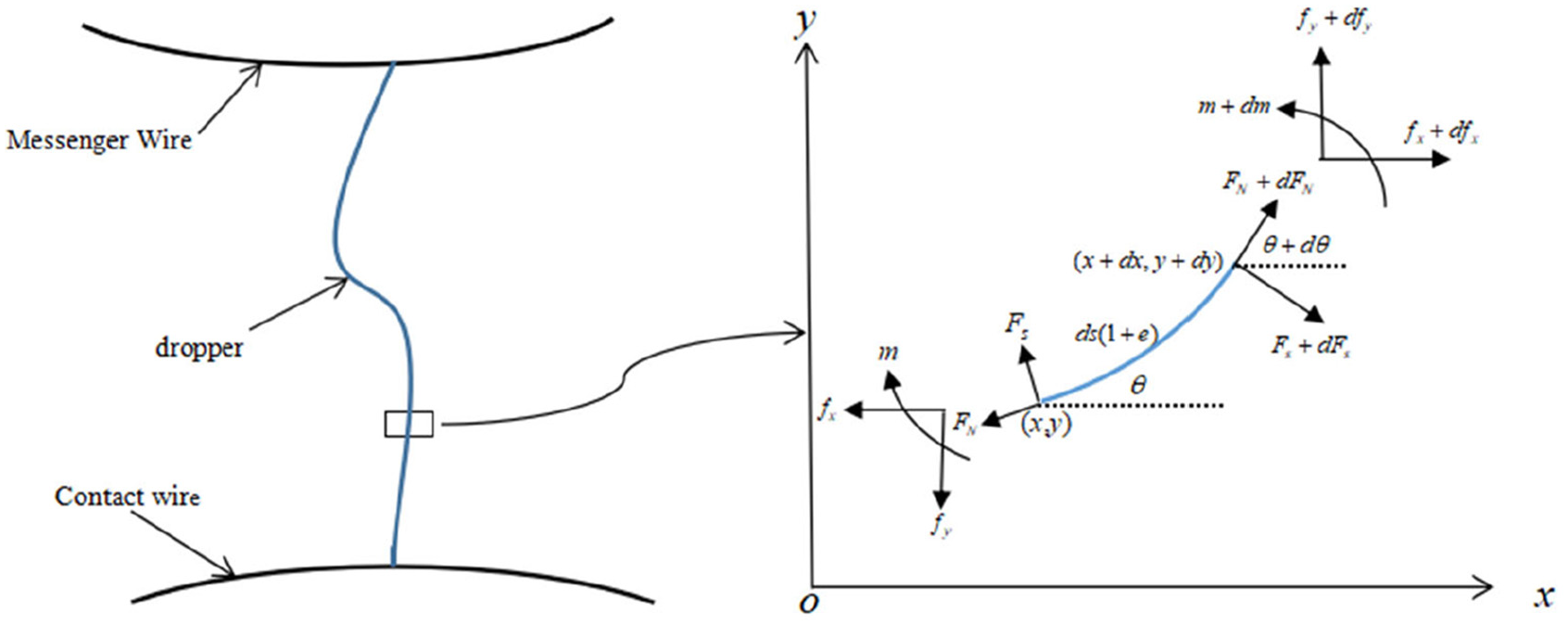
Force analysis diagram of micro-element segment of dropper.
In order to simplify and facilitate the subsequent calculation, we first refer to the following dimensionless variables:

Where
Through the analysis of the stress on the dropper, the axial strain of the micro element segment of the dropper caused by the axial tension. According to the relationship between the definition of strain and the arc length of the dropper element and the location coordinates x, y, the axial strain of the dropper element caused by the axial tension can be obtained as follows.

The axial tension of the dropper element can be expressed as.

Also

where,
Therefore, from the axial strain of the micro element segment of the dropper, we can get

From the bending deformation equation and the differential relationship between bending moment and shear force, the following equation can be obtained.


The equation of motion of the micro element segment of the dropper is as follows.


The differential relationship between the angle

All the above equations can be sorted into the following equations:


Where,
Initial and boundary conditions of each dropper
There is the following initial condition.

Boundary conditions are as follows.


Where,
Parameter acquisition of dropper
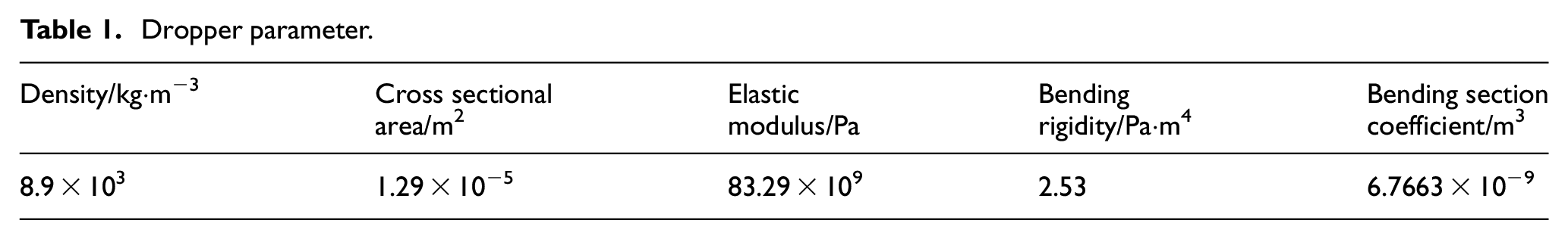
The dropper is mainly made of copper. We measure the elastic modulus of the dropper using universal material testing machine and electronic extenometer. In this paper, the bending rigidity of the dropper is obtained using the calculation formula based on the Costello 18 model. In the calculation of dropper stress, the parameters of required parameters are shown in Table 1.
Dropper parameter.
Numerical calculation method
A set of equations (32) cannot be solved analytically, it has to be solved by a numerical method. In this paper, the finite difference method is used to solve the numerical solution by writing a MATLAB program. The whole dropper is divided into n equal length elements. The dimensionless length of each element is
The partial differential about arc length coordinate and time in the equations can be expressed approximately as follows.


Substituting the above expressions into the system of equations (32).The number of discrete elements n and time step
The flow chart of the specific solution process is shown in Figure 3 using the finite difference method and compiling the MATLAB numerical program to calculate the stress of the dropper.

Flow chart of stress calculation of the dropper.
Results
We perform the calculation when the load acts on the middle of the contact wire. The numerical results can be obtained by using the finite difference method.
Stress change of dropper I
Because the catenary model has the characteristics of symmetry about dropper III, when the load acts on the middle of the contact wire, only the stresses of dropper I, II, and III need to be calculated. When the load acts on the contact wire, it will cause the vibration of all droppers in a span, which will change the stresses of the droppers. It can be seen from Figure 4 that the stress change of dropper I experiences three stages in a period when there is no tension at both ends of the contact wire.

Stress change of dropper I with no tension.
When the tension is 15 kN, the stress change of dropper I is as shown in Figure 5. The stress change is very different from the condition that there is no tension. There is no attenuated vibration stage, and the vibration degree of dropper is also very different. When there is no tension at both ends of the contact wire, the maximum tensile and compressive stresses of dropper I are 160 MPa and 90 MPa, which are eight times and more than 11 times of those with the tension of 15 kN. Furthermore, the time to reach the maximum tensile and compressive stress is much longer.

Stress change of dropper I with the tension of 15 kN.
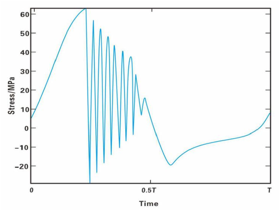
When the tension is 30 kN, the stress change of dropper I is similar to that with the tension of 15 kN, which experiences a maximum tensile stress and a maximum compressive stress. However, the maximum tensile and compressive stresses are lower than those with the tension of 15 kN (Figure 6).

Stress change of dropper I with the tension of 30 kN.
Stress change of dropper II
Compared with the stress change of the dropper I, it still takes a long time for dropper II to reach the maximum tensile and compressive stress values, but there are obvious attenuated vibration stage and bending compression stage with the tension of 15 kN. The degree of stress fluctuation is much weaker than that with no tension, which is caused by the influence of tension at both ends of the contact wire. The vibration amplitude of the dropper is reduced, and the change degree of stress caused by the vibration is also be weakened (Figure 7).
Stress change of dropper II with the tension of 15 kN.
When the tension is 30 kN, the stress change of dropper II is different from that with the tension of 15 kN (Figure 8). Under the condition, the attenuated vibration stage disappears. It can be seen that the stress of dropper II changes with time in the form of sinusoidal vibration basically, which is lower than the stress value of dropper II when the tension is 15 kN.

Stress change of dropper II with the tension of 30 kN.
Stress change of dropper III
From Figure 9, it can be seen that the maximum tensile and compressive stress values of dropper III are much larger than that of dropper II. Compared with other droppers, the three stages of stress change are very obvious. The time required for the instant rebound stage with the tension of 15 kN is much shorter than that of dropper II.

Stress change of dropper III with the tension of 15 kN.
When the tension is 30 KN, dropper III does not experience the attenuated time during the vibration process (Figure 10). However, when the tension is 15 kN, the vibration amplitude of dropper III is large and the attenuated time is long. Therefore, a proper increase in the tension of the contact wire will reduce the vibration amplitude of the dropper and reduce the fatigue damage of the dropper.

Stress change of dropper III with the tension of 30 kN.
Discussion
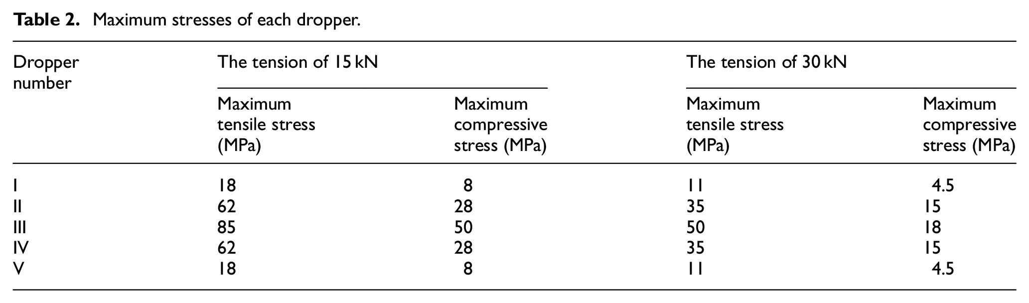
Based on a finite element simulation, Wu performed the lifting amount of dropper and got stress images under different tension. Wu’s et al. 19 results are consistent with ours. The maximum tensile and compressive stresses of each dropper can be found from the above figures and they are listed in Table 2. When the tension is 30 kN, it is found that the maximum tensile stress of dropper III is about 1.43 times of that of dropper II, and 4.55 times of that of dropper I. When the tension is 15 kN, the maximum tensile stress of dropper III is about 1.37 times of that of dropper II and 4.72 times of that of dropper I. When the load acts on the contact wire, the dropper will produce vibration, which will be transmitted through the contact wire and cause the vibration of the dropper. According to the calculation, although the tension is different, the vibration intensity of the dropper increases with the closer distance away from the load location, and then the maximum tensile stress also increases. Therefore, the greater the vibration of the dropper, the larger the stress change.
Maximum stresses of each dropper.
It can be seen from the condition of no tension that when the load acts on the middle of the contact wire, the stress of the dropper will go through three stages. Compared with the tension at both ends of the contact wire, the stress change of the dropper is very different. After the tension is increased, the dropper stress no longer goes through three stages, and the time to reach the maximum tension and compressive stress values is longer. When the tension is 15 kN, there is no attenuated vibration stage for dropper I, while there are obvious attenuated vibration and bending compression stages for droppers II and III. When the tension is 30 kN, the stress changes of each dropper are the same, and there is no attenuated vibration stage. It can be seen that with the increase of the tension, the faster the decay rate of the stress is, the shorter the decay time is. The decrease of the vertical displacement amplitude of the dropper leads to the acceleration of the attenuation of the dropper stress. The shorter the decay time is, the less the compressive stress cycles the dropper experiences, which is beneficial to improve the fatigue life of the dropper.
Under the different tensions, the relationship between the maximum tension and compressive stresses and the location of the dropper is shown in Figures 11 and 12. It can be seen that the change of dropper location has a certain impact on the maximum tensile and compressive stresses. Due to the symmetry with respect to dropper III and the vertical displacement of the dropper, the maximum tensile stress is also symmetrical with the change of location. It can be seen from the change trend of the maximum tensile stress that the maximum tensile stresses of each dropper are also different due to the different tensions. The larger the tension, the lower the maximum tensile stresses of each dropper. The difference of the maximum stress of each dropper caused by different tension cannot be ignored, which provides a way to improve the dropper fatigue life.
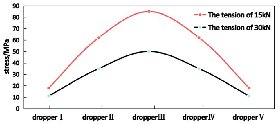
Comparison of maximum tensile stresses of each dropper.

Comparison of maximum compressive stresses of each dropper.
Dropper is subjected to cyclic stresses which can cause mechanical damage. Thus, it will induce fatigue crack and any arbitrary shape of crack initiation will grow with semi-elliptical shape. Then, the fracture response is provoked.20–22 In the actual operation of the contact wire, the tension at both ends of the contact wire can be increased scientifically, which can effectively reduce the fluctuation amplitude of the contact force between the pantograph and the catenary system. Through optimizing the relationship between the pantograph and the catenary system, and further reducing the failure caused by the fatigue fracture of the dropper, it can meet the operation safety of the electrified train. However, if the tension of the contact wire exceeds a certain range, it will affect the elasticity of the contact network, and result in the reduction of the current collection quality of the pantograph, which will bring potential safety hazards for the train operation.
Conclusion
The effects of contact wire tension on dropper stress are concerned in this paper. The change of dropper stress is performed using the numerical and analytical models. The conclusions can be drawn as follows.
The stress amplitude and the maximum tensile stress of the dropper with the tension are significantly lower than those without the tension. The larger the tension is, the lower the stress amplitude and the maximum tensile stress of the dropper are.
During a period, there are three stages in the change of dropper stress with the low tension. Namely, instant rebound, attenuated vibration and bending compression stages. However, the attenuated vibration stage disappears when the tension is increased to a certain extent.
Footnotes
Handling Editor: James Baldwin
Declaration of conflicting interests
The author(s) declared no potential conflicts of interest with respect to the research, authorship, and/or publication of this article.
Funding
The author(s) disclosed receipt of the following financial support for the research, authorship, and/or publication of this article: This work has been supported by Research Project of China Academy of Railway Sciences Corporation Limited (2019YJ137).