
Abstract
In this paper, the influence of wind load on the stress characteristics of dropper for a high-speed railway is studied. The section method is used to obtain the vibration equation of the dropper, and the finite difference method is used to convert the partial differential equation of the dropper vibration into a finite difference equation. Through the force analysis of the contact line section upwind, the vibration equation of the contact line with air damping is obtained. Thus, the partial differential equation of the motion can determine the initial and boundary conditions of each dropper. The MATLAB program is written to obtain the stress change diagram of each dropper, and the influence of wind load on the stress characteristics of the dropper is analyzed. The results show that the maximum tensile and compressive stresses of each dropper are different due to the difference of wind load and dropper location, and the dropper in the middle location is most sensitive to the change of wind load. At a low wind speed, there are immediate rebound and obvious attenuation vibration stages during the stress change of dropper. In addition, with the increasing speed of wind load, the stress amplitude and the maximum tensile stress of dropper do not almost change or decrease except the middle dropper.
Introduction
With the continuous development of high-speed railways, as a key component of the catenary system, dropper breaks frequently and its failure has become a prominent problem in the safe operation of high-speed railways. During the course of railway transportation, if the broken dropper cannot be detected and repaired in time, the contact line will sink and cause it to be non-parallel with the track, and the pantograph flow will be affected completely. After the broken dropper sags, it is easily entangled with the contact line under the action of wind, which will damage the pantograph, causing train operation failure and endangering the life and property safety of passengers. Therefore, it is very important for the analysis of failed dropper to find the reason and for the design to improve the service life of dropper and ensure the safety and reliability of the catenary system.
Good dynamic performance of pantograph-catenary is the key factor to ensure the safe operation of train, and the change of dynamic characteristics of pantograph-catenary caused by high-speed operation of electric locomotive has attracted the attention. 1 Pombo studied the influence of aerodynamic force on the dynamic performance of pantograph-catenary under cross wind, and emphasized the key factors of environmental wind on the contact performance of pantograph-catenary. 2 The nonlinear displacement method proposed by Lopez-Garcia et al. 3 is more accurate than the traditional finite element method. Tur et al. 4 put forward the form finding method of catenary. Finner et al. 5 proposed to use Bernoulli beam element to equivalent contact line based on the idea of catenary modeling with finite difference method. The finite element method is widely used because of its high accuracy. Ambrósio and Pombo6–11 used the finite element method to establish the catenary model and study the dynamic characteristics of multi pantograph-catenary. Cho et al. 12 and Cho 13 used this method to study the influence of catenary pre sag on pantograph-catenary current collection quality. Scanlon measured the aerodynamic coefficients of a British railway contact line through wind tunnel experiments, and preliminarily judged the instability conditions of the contact line. 14 Stickland et al. 15 and Stickland and Scanlon 16 used the von Karman form of wind power to simulate the transverse and longitudinal fluctuating wind fields.
At present, the researches mainly focus on the improvement of the dropper pre-configuration method, the fatigue characteristics analysis of the dropper and the development of its fatigue testing machine considering the bow-net resistance. However, there are relatively few studies on the dropper stress changes when different wind loads are considered. The purpose of this paper is to study the influence of wind load on dropper stress in a simple suspended catenary system.
Vibration equation of dropper
Vibration equation of dropper
The stress change is the most fundamental reason for the fatigue fracture of the dropper. In order to study the stress change of the dropper during the vibration process, the micro-element segment of the dropper is selected for force analysis, which is shown in Figure 1.

Force analysis diagram of dropper.
In Figure 1,
In order to simplify the equation, the following dimensionless method is introduced.
Where,
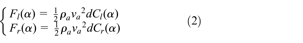
Thus, according to the force analysis, the following equation set can be obtained.

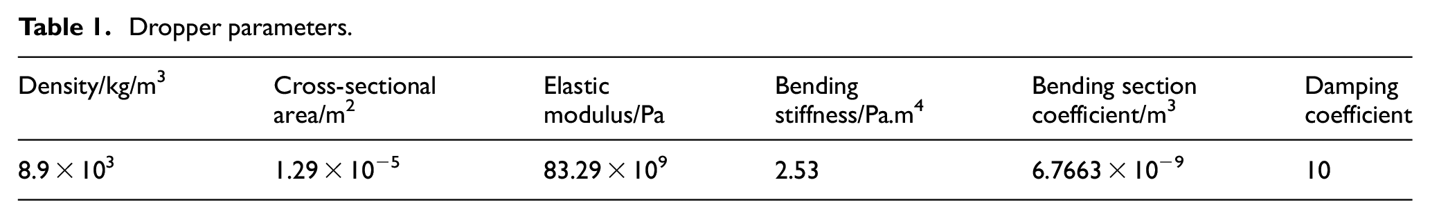
The parameters of the dropper
The elastic modulus of the dropper is measured by universal material testing machine 17 and electronic extensometer, and the bending stiffness is obtained by Costello model. 18 The parameters of the dropper involved in the calculation process are shown in Table 1.
Dropper parameters.
Finite difference method
The vibration equation of the dropper is a partial differential equation system. It is difficult to directly obtain the analytical solution. The numerical solution can be solved by numerical methods. Here, the finite difference method is used. The steps to calculate the stress change of the dropper with time by the finite difference method are as follows.
① The dropper is discretized into equal length elements, and the numbers of the elements determine the accuracy of the calculation results. In the process of trial calculation, we observe the calculation results under different numbers. When the numbers is less than 16, the result error is large. When the numbers is greater than or equal to 64, the calculation time is too long. Therefore, the numbers are set to be 32, and the discrete time is
② The dimensionless difference schemes are obtained as follows.


③ By introducing the difference scheme into the equation set (1), the difference equations of dropper vibration can be obtained.
Vibration equation of contact line considering air damping
Air damping on the contact line
Studies have shown that there are two main forms of wind load on the catenary, namely average and fluctuating wind loads. This paper mainly studies the effects of average wind load on the stress characteristics of dropper. The contact line’s angle of attack will change under the action of wind load, and the wind force diagram of its cross-section is shown in Figure 2. 19

Windward force diagram of contact line section.
In Figure 2,
Hence, the following equations are obtained.
Where

Let
Assuming that the drag coefficient in the vertical direction is

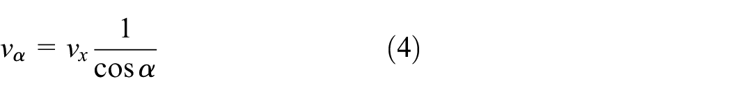
So substituting equations (3) and (4) into equation (5), we can get

Therefore,

Since it is a micro-vibration, it can be regarded as

Where,
From equation (7), we can see

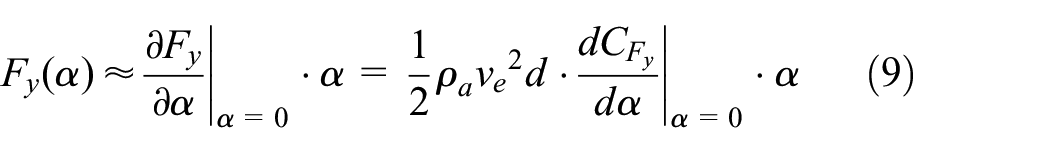
Substituting equation (10) into equation (9), the expression of steady aerodynamic force can be obtained.

Therefore, under the action of cross wind, the air damping on the contact line can be expressed as follows.

Vibration equation of contact line considering air damping
We construct the mechanical model of simple chain suspension catenary, as shown in Figure 3. Here, we let

Mechanical model of simple chain suspension catenary.
The contact line can be considered as a beam. Then, the free vibration equation can be simplified as follows.
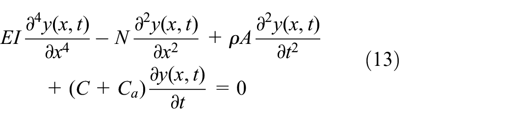
Where EI is the bending rigidity,
Suppose the main vibration of the beam is the following.

Bringing equation (14) into equation (13) and it can be transformed into solving the following equation.

The four eigenvalues of equation (15) are obtained.

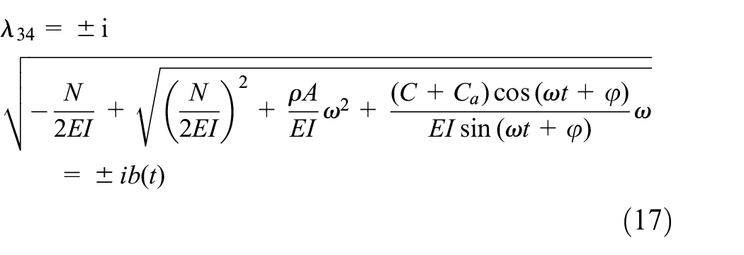
Then, the general solution of equation (15) can be expressed as

The modal function can be obtained by solving

If there is a concentrated force when the distance is c away from the origin and it travels forward at a speed v, thus, the forced vibration equation of the beam is the following.
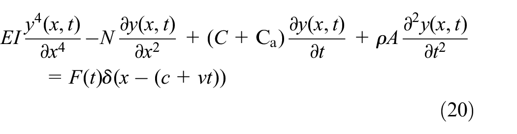
Where the symbol
Suppose the solution of equation (20) is

Substituting equation (21) into equation (20), we can get

After multiplying equation (22) on both sides and integrating along the beam length, we can get

Using the following properties of the modal function, equation (23) is transformed into the following equation.

It can be assumed that the solution of equation (24) is
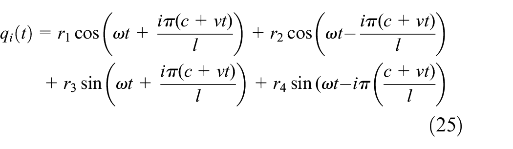
We can get the system of

By solving

Therefore, the response of the contact line is

In order to study the influence of wind load on dropper stress, three cases of 5, 10, and 20 km/h are selected for the analysis. Considering that the influence of higher order is small, only the first five orders are calculated. Therefore, the response equation of the contact line is transformed into the following.
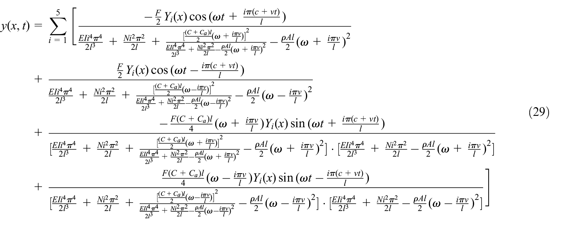
Here, let F = 100 N,
Parameters of the contact line.

The resistance coefficient values.

Initial and boundary conditions of dropper
Regardless of the location of the dropper, the initial and boundary conditions of each dropper can be expressed as follows.


Where, i is the number of the dropper,
Results
Dropper stress when the speed of wind loadis 5 km/h
When the speed of wind load is 5 km/h, the stress changes of dropper I are shown in Figure 4. It is found that when the moving load and the wind load act on the catenary at the same time, the catenary will vibrate due to the effect of the loads, and the dropper will also vibrate due to this effect, and its stress will also change.

The stress changes of dropper I with time.
Because the load moves from left to right at a certain speed, when the moving load acts on the contact line, it will cause the contact line to vibrate, and the vibration will propagate from the left to right in the form of wave along the contact line. Therefore, the motion state of dropper II will change, and the stresses will change with the change of its motion state. The maximum tensile and compressive stresses of dropper II are higher than those of dropper I (Figure 5).

The stress changes of dropper II with time.
It can be seen from Figure 6 that the maximum tensile and compressive stress values of dropper III increase compared with those of dropper I, but the changes of the stress values are not obvious compared with those of dropper II.

The stress changes of dropper III with time.
Compared with droppers I, II, and III, the stress variations of dropper IV have also reached to the maximum tensile and compressive stresses in a short time, but the vibration intensity is different (Figure 7).

The stress changes of dropper IV with time.
The stress variations of dropper V are the same as those of dropper I. Furthermore, its maximum tensile and compressive stresses are not almost different (Figure 8).
The stress changes of dropper V with time.
Dropper stress when the speed of wind load is 10 km/h
When the speed of wind load is 10 km/h, the stress changes of dropper I are as shown in Figure 9. The stress changes are almost the same as those under the condition of 5 km/h. There are not attenuation vibration and bending compression stages, and the changes of dropper vibration degree are not very significant.

The stress changes of dropper I with time.
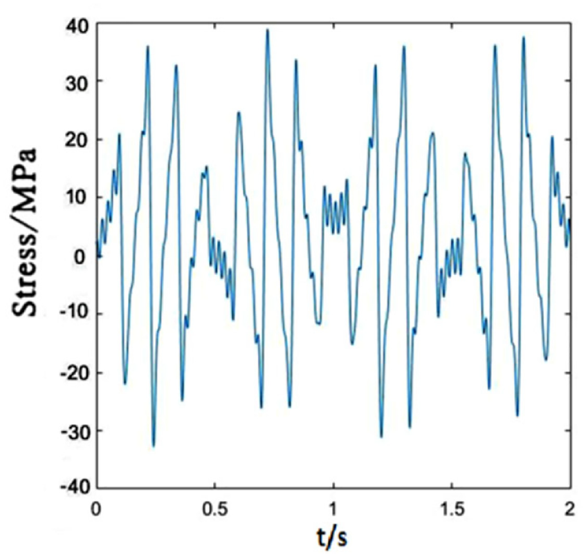
It can be seen from Figure 10 that the maximum tensile and compressive stress values of dropper II are much higher than those of dropper I.

The stress changes of dropper II with time.
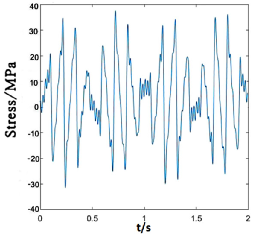
Figure 11 shows that the maximum tensile and compressive stresses of dropper III increase and they are higher than dropper II.

The stress changes of dropper III with time.
Compared with droppers I, II, and III, dropper IV has the same vibration conditions, but its vibration amplitude and its tensile and compressive stress values are lower than those of dropper III (Figure 12).

The stress changes of dropper IV with time.
The stress changes of dropper V are shown in Figure 13. It is observed that they are not sensitive to the speed change of wind load and they do not increase with the speed increase of wind load. The maximum tensile and compressive stress values hardly change.
The stress changes of dropper V with time.
Dropper stress when the speed of wind load is 20 km/h
When the speed of wind load is 20 km/h, the stress changes of dropper I are shown in Figure 14. The maximum tensile and compressive stress values do not almost change with the speed increase of wind load.
The stress changes of dropper I with time.
Figure 15 depicts the stress changes of dropper II. The maximum tensile and compressive stresses are only a little different from those under the condition of 10 km/h.

The stress changes of dropper II with time.
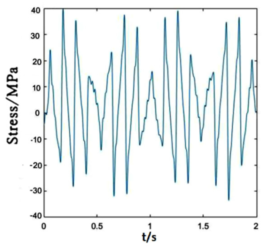
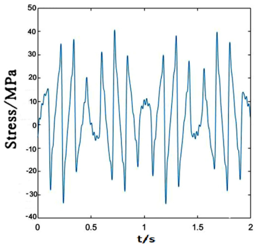
Compared with droppers I and II, the vibration amplitude of dropper III is highest. The maximum tensile and compressive stresses are highest (Figure 16).
The stress changes of dropper III with time.
The stress of dropper IV fluctuates under the influence of the loads. However, compared with the speed of 10 km/h, the changes in maximum tensile and compressive stresses are not very obvious (Figure 17).

The stress changes of dropper IV with time.
Compared with other droppers in a span, the vibration amplitude of dropper V is almost the same as that of dropper I (Figure 18).
The stress changes of dropper V with time.
According to the above figures of each dropper under different speeds of wind load, it could be found that there are usually two stages during the period of the stress changes, including immediate rebound and attenuation vibration stages. The difference is that the attenuation vibration stage is more obvious when the speed of wind load is low.
Discussion
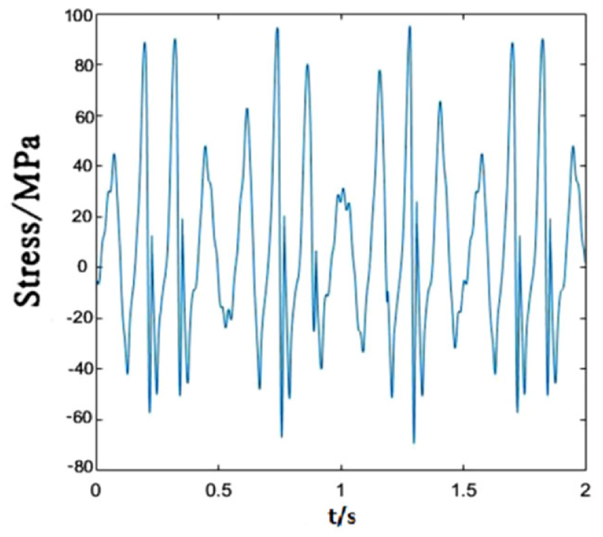
When the moving load at a speed of 300 km/h acts on the contact line and the wind load acts on the droppers at different speeds, the maximum tensile and compressive stresses of each dropper are shown in Table 4. There is almost no change in the maximum tensile and compressive stress values of droppers I and V under different wind speeds, but the stresses of droppers II, III, and IV fluctuate with the change of wind speed. It can be seen that the dropper in the middle location is most sensitive to the changes of wind speed. This is similar to the analysis of dropper failures from the perspectives of vibration realization, bending deformation, and bending characteristics in the literature. 21 It is found that the maximum tensile and compressive stress values of droppers II, III, and IV are higher than those of droppers I and V under the same wind speed. It is in agreement with the conclusion obtained by Wu et al. 22 Specially, the compression amplitude and the repeated bending frequency of dropper III are the largest and it is prone to fatigue and fracture.
Maximum stress of each dropper.
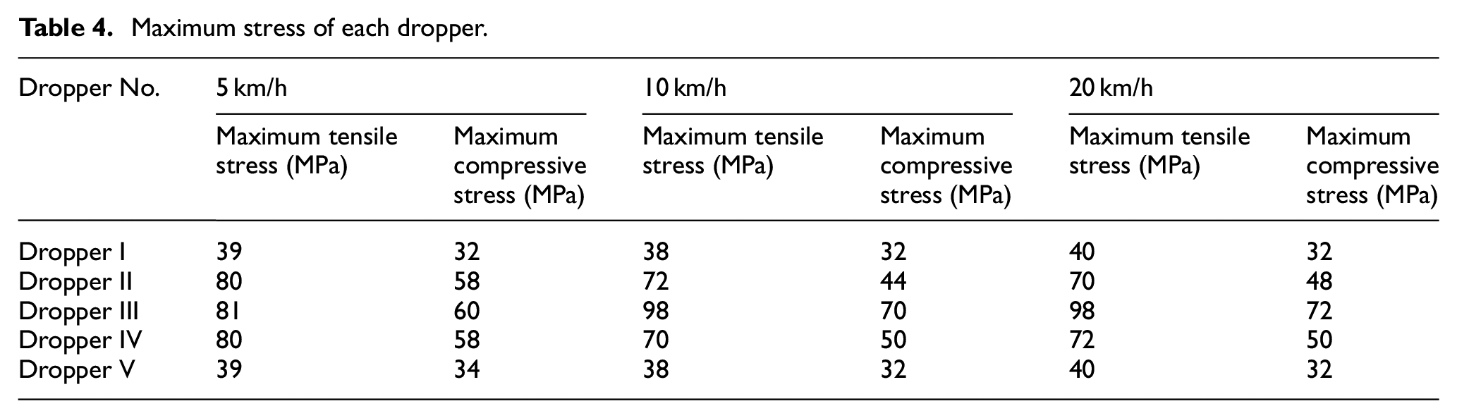
In addition, it can be seen that the speed of wind load has a certain influence on the maximum tensile and compressive stresses of each dropper. The maximum tensile and compressive stresses of each dropper are basically symmetrical with respect to dropper III, which is due to the symmetry of the simple chain catenary model established. From the variation trends of the maximum tensile stress, it can be seen that the maximum tensile stresses of some droppers at 20 km/h are lower than those at 5 and 10 km/h. It illustrates that the stress amplitude and the maximum tensile stress of some droppers decrease with the increasing speed of wind load. In other words, it may be beneficial to the life of dropper under a low speed of average wind load.
When considering the influence of wind load on the stress characteristics of dropper in the catenary model, this work shows that the maximum tensile and compressive stresses of dropper decrease under the action of wind load, and the number of tensile and compressive stress cycles of dropper decrease. Certainly, this is beneficial to prolong the service life of dropper. With the continuous development of high-speed railway, higher requirements are put forward for the service life of dropper, and the train is affected by more complex environment in the process of driving. By studying the influence of wind load on dropper stress, it can provide theoretical basis for the optimization of key parts of high-speed railway and the maintenance in the process of application, and provide important practical significance for the system of its maintenance plan. Shen 23 established the pantograph-catenary dynamic model for dynamic simulation, and studied the influence of different wind speeds on the pantograph-catenary current collection characteristics. Shen’s results show that the wind load will have a positive damping effect under certain conditions at a low wind speed, and the pantograph-catenary current collection is improved. This is consistent with our results in this paper. In some cases, wind load can reduce the failure caused by the fatigue fracture of the dropper.
It should be pointed out that fluctuating wind load acts on the catenary in actual operation. Further, higher wind speed could occur and the angular attack of the airflow could change. These effects must have the impact on dropper stress. Thus, our future work will include them.
Conclusion
In this paper, the force analysis of the contact line section is performed in the windward direction by using the micro element method. The vibration equation of the contact line considering the average wind load is obtained. The response of the dropper is obtained through calculation, and then the stress changes of each dropper under different wind speeds are obtained by writing a MATLAB program combined with the vibration equation of the dropper. The conclusions can be drawn as follows.
In the catenary model, considering the effect of average wind load at a low wind speed, the stress changes of dropper experience immediate rebound and obvious attenuation vibration stages. Generally, with the increasing speed of the average wind load, the stress amplitude and the maximum tensile stress of dropper do not almost change or decrease except the middle dropper.
When the wind load acts on the catenary, the maximum tensile and compressive stresses of each dropper are different due to the difference of wind speed and dropper location, and the dropper in the middle location is most sensitive to the speed change of wind load.
Footnotes
Handling Editor: Chenhui Liang
Declaration of conflicting interests
The author(s) declared no potential conflicts of interest with respect to the research, authorship, and/or publication of this article.
Funding
The author(s) disclosed receipt of the following financial support for the research, authorship, and/or publication of this article: This work is supported by Research Project of China Academy of Railway Sciences Corporation Limited (2020YJ022).