
Abstract
The dropper through bends and bears dynamic impact load before and after the train passes in actual service, which has an important impact on the fatigue life of the dropper. In this paper, a simulation model which can simulate the interaction between pantograph and catenary is established by using the numerical simulation method. A dropper model which can simulate the dynamic stress of the dropper is established through the beam-link combination element. The simulation result shows that among the six droppers in a span, the dynamic force of No. 1 and No. 6 droppers is the smallest, and the dynamic force of No. 3 and No. 4 droppers is the largest. The dynamic load variation characteristics of the dropper are characterized by the dynamic coefficient. When the front and rear pantograph pass through, the maximum dynamic force of the dropper appears when the rear pantograph passes through. The maximum dynamic force is located in the middle of the dropper. Through the research of this paper, the simulation method of catenary and dropper is established, and the dynamic stress process of dropper is analyzed, which lays a technical foundation for the subsequent research on the fatigue failure mechanism of dropper.
Introduction
Catenary is an important part of high-speed railway. It mainly supplies power to the train through sliding friction with the pantograph on the top of the train.1,2 Dropper is an important part of catenary. One end is connected with load-bearing cable and one end is connected with contact wire. It mainly plays the role of bearing and current carrying.3,4
During actual train operation, the dropper is in a static state and mainly bears gravity loads such as contact wire before the train passes through. The dropper rises upward and bends, and then falls downward to bear the dynamic impact load when the train passes by. The dynamic impact load of dropper has an important influence on the fatigue life of dropper. However, it is difficult to measure the dynamic force of the dropper on site, because the catenary is charged and affected by the train operation. It is necessary to study the dynamic load of the dropper by numerical simulation.
Chen et al. 5 used the MATLAB numerical calculation program calculated the stress variation of the dropper, and analyzed the influence of frequency and vibration on the stress of dropper.
He et al. 6 used the MATLAB to analyze the influence of catenary tension on the stress of the integral dropper. Liu et al. 7 investigated the lumped-mass distribution in single-pantograph and multi-pantograph operations with help of a 3D pantograph-catenary finite element model.
Bruni et al. 8 describe the results of a benchmark concerning the simulation of pantograph-catenary interaction. Harèll et al. 9 studied influence of the critical sections on dynamic performance of pantograph catenary during multiple pantograph operation. Pombo et al. 10 analyzed the influence of aerodynamics on the dynamic performance of pantograph catenary. Tang et al. 11 studied the current collection performance between pantograph and catenary at different speeds by ANSYS simulation analysis technology. Guan et al. 12 established the dynamic simulation models of pantograph, catenary, and pantograph catenary contact at different speed levels by using the finite element method, and the dynamic performance indexes of pantograph and catenary are obtained.
The dropper bears the dynamic impact and repeated bending process in the service process. The dynamic impact process of dropper has an important influence on the service life of the integral dropper. However, there are few simulation studies on the dynamic force process of dropper. How to effectively calculate its dynamic impact and bending process at the same time is an important difficulty in the simulation process. Through the finite element method, this paper studies and establishes a pantograph catenary simulation method which can simulate the bending and impact process at the same time, and studies the dynamic impact process of the suspension string when the double pantograph passes by. The dynamic coefficient of dropper is proposed and to characterize the dynamic force of dropper. There are different axial loads at different positions of the dropper strand, and the stress state of the same position is also changing at different times.
Simulation model establishment
Establishment of finite element model
Finite element method (FEM) is a numerical method, which discretizes the continuous system and is widely used in the dynamic calculation of pantograph catenary. The FEM is used to build the catenary model in this paper. The catenary is divided into several elements, and the elements are connected by nodes. The displacement of the nodes is taken as the basic unknown parameter to analyze the characteristics of multiple elements and establish the dynamic equation.
The catenary is composed of suspension device, support device, positioning device, catenary mast and foundation. This paper focuses on the dynamic characteristics of dropper of the catenary. Therefore, the influence of pillar, foundation, support device, and auxiliary equipment on the catenary is not considered when establishing the calculation model. Only the catenary model composed of positioning device and suspension device is studied, and the model is simplified accordingly to the following:
It is assumed that the catenary mast and supporting device are completely fixed, that is, the influence of catenary mast and supporting device on catenary is ignored, and only the contact wire, messenger cable, elastic sling, and dropper in suspension device are modeled.
The cantilever is simplified as hinged support, and the displacement constraints are imposed in Y and Z directions. The positioner is simplified as lumped mass element and Z direction displacement constraints, and the tension compensator is simplified as constant tension.
The simplified model of catenary is shown in Figure 1. The messenger cable, contact wire, and elastic sling are constructed by beam 188 element based on Timoshenko beam theory, which considers bending deformation and shear deformation, and can better simulate the non-linear behavior in static and dynamic analysis of catenary. The element stiffness matrix is as follows formula (1).


The simplified model of catenary.
where

where
The dropper is modeled in two modes. Firstly, the dropper is always in the tension state in the static form finding analysis, and the internal axial force is consistent, so the dropper can be equivalent to a single rod element (cable element). The bending stiffness is small and cannot be ignored when studying the stress of different positions of the dropper especially, 13 and the discrete model of the dropper must be established in the dynamic simulation. Therefore, the dropper with the largest compression amplitude is taken as an example to establish a finite element model with the characteristics of the dropper structure in the dynamic simulation.
The three-dimensional finite strain bar element link180 is used in static analysis. The element not only has the characteristics of ordinary spatial bar element, but also has the characteristics of tension without compression by changing the stiffness variable. The element mass matrix is shown in formula (3).

where
k = 1; when the dropper is in tension,
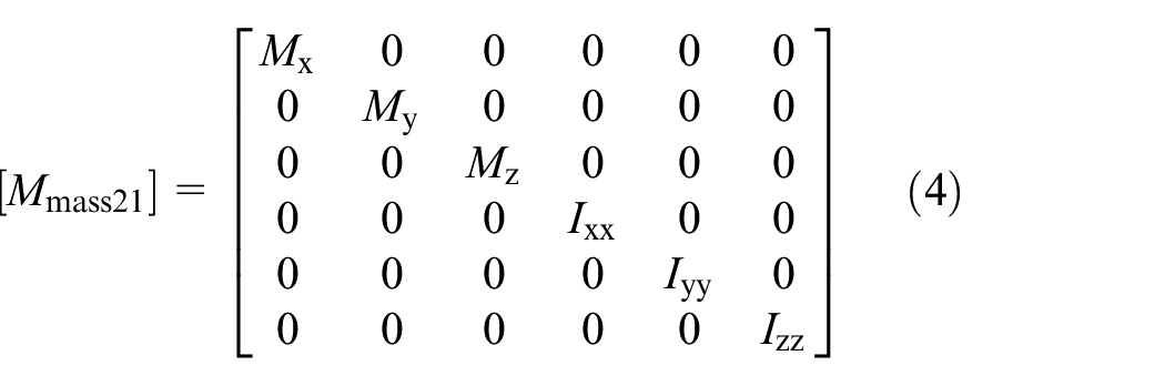
The dropper clamp and positioner are constructed by mass point element mass21, which has the freedom of movement in X, Y, and Z directions and the freedom of rotation around X, Y, and Z axes. Different mass and rotational inertia can be applied in each coordinate direction. The mass parameters of mass21 element are defined by the equivalent mass of dropper clamp and positioner. The element mass matrix is shown in formula (4).
The motion differential equation of the finite element model of catenary is shown in formula (5).

where
The geometric model of catenary can be constructed after inputting the relevant modeling parameters, and the grid can be divided according to different element types and material properties. The Y and Z displacement constraints are applied at the suspension point of catenary, while the Z displacement constraints are applied at the locator equivalent point of contact wire, and the messenger cable and contact wire are tensioned with constant tension. The tension of the elastic sling is applied to the beam element that constructs the elastic sling in the form of preload. The part finite element model of the catenary is shown in Figure 2 and the material parameters are shown in Table 1.

Finite element model of the catenary (part).
Material parameters of the catenary.

Static form finding
The calculation of initial balance position of catenary is different from the conventional structural analysis. The model used in the initial balance calculation is unknown, which needs to be determined by the position of the balance state and the final balance position of the contact wire, which is known. The static form finding of catenary is to determine the initial shape and stress state of catenary when the catenary reaches the required balance position. The initial state will play an important role in the study of dynamics of pantograph catenary system. The accurate catenary mathematical model be established only by obtaining the correct geometric parameters and stress distribution of the catenary at the initial balance position, and provide necessary basic data for the subsequent study of the dynamic behavior of the pantograph catenary system. The static shape finding of the catenary is a process of continuous optimization of the structure.
The balance position between the catenary structure and the contact wire is known during the form finding of the catenary system. If the length of dropper which connecting the messenger cable and the contact wire is determined, the geometric parameters and initial stress distribution of the balance position can be determined accordingly. Therefore, the catenary form finding problem is also the problem of calculating the length of dropper that meets the requirements of the initial balance state.
In order to obtain the balance state of catenary in the ideal state in this paper, the combination of split mode method and negative sag method are used together to adjust the length of dropper for iterative calculation for many times. The catenary generates vertical displacement under the action of tension and self-weight. The offset of the catenary from the balance position is obtained through calculation, and the length of dropper is adjusted by the offset. Then the catenary model is reconstructed and calculated. After several iterative calculations, the balance position can be reached after the catenary calculation.
At the same time, during the erection of catenary, the geometric deformation of messenger cable and contact wire will also cause the change of its stress state. Therefore, during the form finding analysis of finite element model, the erection process should be simulated to obtain the initial stress state of catenary caused by the change of clue geometry. During the actual installation and construction, the installation sequence is that the messenger cable, mid-point anchor, and the elastic sling and contact wire are anchored at the same time, and the anchor and dropper devices are installed. Due to the deformation of the contact wire and the messenger cable under the action of gravity and tension, the node coordinates will also change during the form finding process. During each iterative calculation, the X-direction coordinates of the upper and lower nodes of the dropper shall be corrected, and ensure that the hanging position of the dropper will not deviate when the length of the contact wire and the messenger cable changes under tension. Therefore, the finite element modeling process for simulating catenary erection can be summarized as follows:
Establish the finite element model of the messenger cable and the contact wire and the initial state is a straight line. The Y and Z displacement constraints and rotation constraints are applied at both ends, and the corresponding tension load is applied, as shown in Figure 3(a)).
Apply displacement constraints in Y and Z directions at the cantilever suspension position of the messenger cable, apply displacement load at the clamping point of the elastic sling of the messenger cable, and pull the node on the messenger cable model to the suspension position of the elastic sling. Apply displacement load at the clamping point of the positioner of the contact wire, and pull the connection position from the node on the contact wire model to the positioner (see Figure 3(b))).
Solve the deformation of the messenger cable and the contact wire by applying gravity, update the geometry of the finite element model by using the node displacement data obtained, add the finite element model of the elastic sling to the updated model, apply preload to tension the elastic sling, and apply corresponding displacement load at the sling clamp position of the messenger cable and the elastic sling according to the length of dropper. Pull the node from the clamp position of the messenger cable and elastic sling to the suspension position of the dropper, as shown in Figure 3(c)).
Solve again and update the geometry of the finite element model. Obtain the finite element model of catenary, which including the initial stress change caused by the geometric deformation of the messenger cable and the contact wire (see Figure 3(d))).
Extract the Y-direction offset of the hanging point of the contact wire of the dropper, and subtract the offset from the length of the dropper. Extract the X-direction offset of the messenger cable and contact wire suspension point of the dropper, and subtract the offset from the X-coordinate of the dropper suspension point. The design height of the contact wire is known, and its balance position should meet the smoothness requirements that the Y-direction coordinates are distributed within ±5 mm of the design height of the contact wire. Extract the Y-direction coordinates of all nodes on the contact wire in the catenary model and judge whether it meets the requirements.
Go back to the first step and recalculate under the coordinates of the new dropper length and dropper suspension point if the smoothness requirement is not met. The calculation is completed when the smoothness requirement is met.

Finite element modeling process for simulated catenary erection: (a) initial state, (b) traction status, (c) complete traction, and (d) installation of dropper.
The simulation process of catenary erection process is combined with the static shape finding analysis of catenary, and to finally obtain the initial model of catenary under given conditions. The calculation process is shown in Figure 4.

Calculation process of initial model of catenary.
Pantograph model
Pantograph can be divided into pantograph head contact strips, frame, suspension spring, and support structure. The frame is divided into upper frame (upper arm) and lower frame (lower arm). At present, the pantograph is generally modeled by lumped mass model and multi-body dynamics model. The multi-body dynamic model is closest to the complete structure of the pantograph. However, due to its high degree of freedom, large model volume, and long dynamic calculation time, the model is suitable for studying the local structure optimization of the pantograph.
This study focuses on the dynamic characteristics of the dropper, and pays less attention to the stress of the pantograph structure. The selection of the lumped mass model can meet the calculation requirements, and this model is the quickest for the dynamic coupling calculation of pantograph and catenary. Based on the kinetic energy equivalence principle, the pantograph structure is simplified and equivalent to a three mass spring damping system, where

Pantograph model with three lumped masses.
The differential equation of pantograph motion is as follows:


The above three dynamic equations are written in matrix form:

Where
The pantograph parameters are shown in Table 2.
Pantograph parameters.

The finite element model of dropper
In the static form finding analysis of catenary, the dropper is only subject to the tension between the contact wire and the messenger cable, so the dropper can be simplified into a single rod element. However, the bending stiffness of the dropper when it is relaxed cannot be ignored in the dynamic simulation of pantograph catenary. 13 In order to obtain the dynamic loads at different structural positions of the dropper, the finite element model that can reflect the structural characteristics of the dropper must be established.
The dropper is mainly composed of contact wire dropper clamp, messenger cable dropper clamp, cardioid ring, clamp pipe, connecting clamp, dropper wire, etc., as shown in Figure 6. In order to accurately calculate the dynamic load of dropper under pantograph catenary interaction, it is necessary to carry out a complete structural modeling of the dropper, especially to establish a strand finite element model that can reflect the tensile and non-stress resistance of dropper strand.

The dropper structure diagram.
The link-beam dual element is used to jointly establish the finite element model of strand structure in this paper. If a beam element with a small section shares i and j nodes with a link element only in tension but not in compression, the two elements form a new double element. When the element is in tension, the link element and the beam element with a small section bear the tensile force together. The link element is not stressed, and only the beam element with small section provides it with a small flexural stiffness when the element is in compression. The schematic diagram of stacking unit is shown in Figure 7.

Schematic diagram of the link-beam superimposing element.
Other parts of dropper, cardioid ring, and clamp tube are considered as hollow beam structure and constructed by beam element. The contact wire dropper clamp and messenger cable dropper clamp are simplified as mass block element mass. The lifting ring is established in the contact pair of cardioid ring and contact wire and exists in the form of rigid body. Each part and its finite element model are shown in Figure 8. The weight of the real object is simulated by the equivalent mass.

Finite element model of dropper and its components.
After the static form finding analysis of catenary is completed, the dropper in the catenary model adopts a single link element. In order to carry out dynamic simulation and extract the dynamic load of dropper, it is also necessary to replace the dropper finite element model. In the catenary model, delete the old link element dropper model, create a new finite element model that can reflect the structural characteristics of the dropper, and simulate the installation of the dropper in the modeling process considering the pre-stress generated by the installation of the dropper. The specific process is as follows:
Delete the dropper model of the link element established in the static form finding analysis, extract the coordinates of the upper and lower clamping points of the dropper, and calculates the position coordinates of the interface end of the connecting clamp.
Take the upper and lower clamping points of the dropper as the origin and the connecting direction of the two points as the X direction, create a new local coordinate system, establish the initial model of the dropper, and establish a contact pair between the cardioid ring and the dropper, as shown in Figure 9(a)).
Calculate the displacement difference between the end point of the dropper return wire and the interface of the connecting clamp, and apply the displacement difference as the displacement load to the end point of the return wire.
Reload the boundary conditions and loads of the overhead contact system, tension the dropper, pull the return wire to the connecting clamp position, and couple it to the clamp, as shown in Figure 9(b)).

Dropper modeling process: (a) establishment of contact pairs and (b) pull the return wire to the position.
The finite element model including the dropper structure is established in the catenary model, as shown in Figure 10.

Finite element model of the catenary.
Contact definition
After the numerical model of pantograph catenary system and dropper is established, the dynamic force data of dropper can be obtained by dynamic simulation of pantograph catenary system. There is sliding contact between pantograph and contact wire, both of which are affected by contact force. In the finite element model, penalty function method is used to establish rigid flexible contact between catenary and pantograph, as shown in Figure 11.

Contact wire-carbon contact strip diagram.
A rigid flexible contact pair between beams is established between the contact wire and the pantograph contact strip. The pantograph contact strip is a rigid body without mass, and the mass is concentrated on the equivalent pantograph head mass M1. The pilot point of the rigid body is the node where the pantograph head mass unit is located. The contact wire is a flexible body, and contact pair is attached to the discrete beam element of the contact wire.
The lifting force (

Calculation of contact pressure.
Under the action of lifting force (

The contact penalty stiffness (
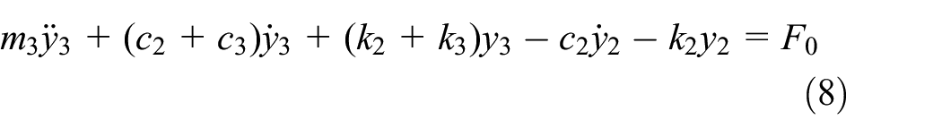
The dynamic equation of pantograph catenary system can be obtained by combining the dynamic equation of catenary (4) and pantograph (8):

The
Simulation method verification
By collecting the dynamic lifting amount of dropper along the high-speed railway, modeling and calculation analysis are carried out by using the actual working conditions during field collection in the simulation, and the simulation model is verified by comparing the actual measured data with the simulation data.
Using the design parameters of high speed railway catenary and pantograph model parameters, establish the dynamic simulation model of pantograph catenary including 16 span catenary, and take the middle span interval to establish the dropper model, as shown in Figure 13.

Dynamic simulation model of pantograph-catenary.
The pantograph catenary dynamic simulation is carried out with the high speed of train passing through this section (350 km/h) measured on site as the input. The actual measurement and simulation of the lifting amount of dropper in the same span are shown in Figure 14.

Comparison of measured and simulated lifting value of dropper.
Comparing the measured and simulated curves in Figure 14, it can be seen that the measured and simulated waveform trends are basically consistent. Although there is a certain difference between the measured value and the simulated value during the fluctuation process of the lifting amount, the measured value and the simulated value are basically close to each other during the stress process of the maximum value of the lifting amount, and the simulation error is within 15%. Therefore, it is considered that the simulation model is more accurate and reliable, and the simulation can reflect the change trend of the dropper. It has certain reference value.
Results and discussion
Static force
The eighth and ninth spans in the middle are taken as the research objects in the established 16 span catenary finite element model, as shown in Figure 15. The axial force of the six droppers is shown in Table 3 when the catenary is in static state. It can be seen that the static tension of No. 1 and No. 6 dropper on the elastic sling is the largest, and the static tension of No. 3 and No. 4 dropper in the middle is the smallest. The analysis shows that the static force difference of the dropper in the same span mainly comes from the different hanging position and inclination degree of each dropper. The inclination of No. 1 and 6 droppers is the largest, and it is far from the adjacent dropper, and the mass of the contact wire bearing the suspension is large, so the static force is the largest.

Finite element model of two spans in the middle of the catenary.
Axial force of the dropper when the catenary is static.
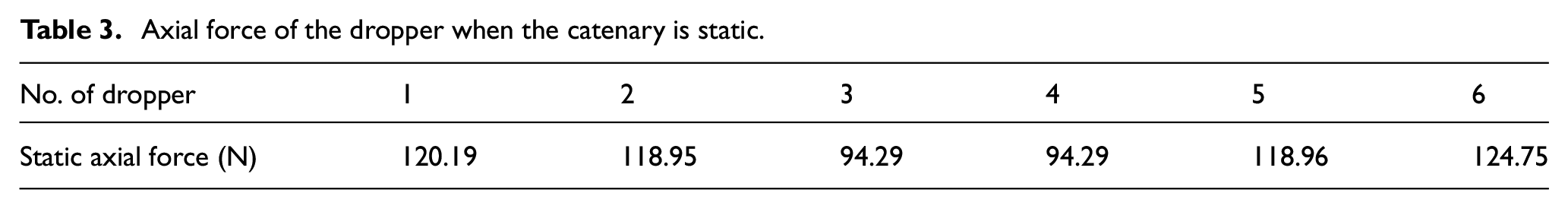
It can be seen that when the catenary is in static state, the stress of the dropper itself is small and there is little difference between each other. Taking No. 6 dropper with the largest static tension as an example, the vertical safety factor of the dropper is 2.5, and the static tension of No. 6 dropper multiplied by its safety factor is 312 N, which is still far less than 1300 N required in China’s railway standard TB/T 2073-2020. Therefore, the static force of the dropper has little impact on the failure of the dropper. The repeated bending and dynamic force in the dynamic response of the dropper excited by the pantograph are the main factors causing the dropper fracture.
Dynamic stress analysis of dropper
The dynamic stress time history of the six droppers under the condition of 300 km/h train passing through the catenary is simulated, as shown in Figure 16. It can be seen that the dynamic forces of the droppers at the symmetrical position in the catenary are basically the same. The maximum dynamic force of six droppers in one span is shown in Table 4.

Dynamic force of six droppers in the same span: (a) dynamic force of No. 1 dropper, (b) dynamic force of No. 2 dropper, (c) dynamic force of No. 3 dropper, (d) dynamic force of No. 4 dropper, (e) dynamic force of No. 5 dropper, and (f) dynamic force of No. 6 dropper.
Maximum value of the dynamic force of six droppers in the same span.
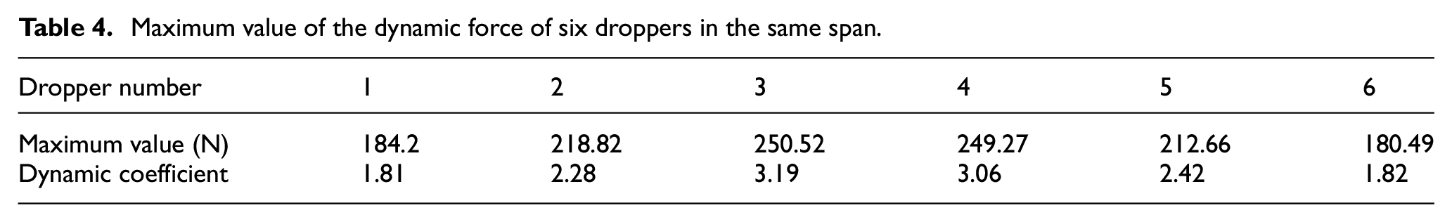
The dynamic coefficient is the dynamic force divided by the static force. The analysis and simulation results show that under the ideal working condition, the dynamic coefficient of the six droppers in a span is between 1.81 and 3.19, the static force of the No. 1 dropper and No. 6 dropper suspended on the elastic sling is the largest, the dynamic force of the dropper is the smallest and the dynamic coefficient is the lowest. The analysis shows that the position of the No. 1 dropper and No. 6 dropper suspended on the elastic sling has good elastic performance, which can keep the dropper in a tensioned state, Therefore, the compression amplitude of No. 1 and No. 6 droppers is the smallest, and the dynamic force is also the smallest; No. 3 and No. 4 droppers have the smallest static force, but the largest dynamic force and the highest dynamic coefficient; The analysis shows that No. 3 and No. 4 droppers are located in the middle of the span, farthest from the catenary suspension and positioning device, and the vibration is the most intense, so the compression is the largest and the stress fluctuation of the dropper is the largest. When the dropper is taken as an integral component, the dynamic force at different positions in the catenary is quite different, and the maximum dynamic force occurs at No. 3 and No. 4 droppers at the mid span.
Dropper force at different positions and at different times
Take No. 2 dropper as the research object. When the train speed is 300 km/h, the distribution of dropper force at different positions and at different times of the strand is shown in Figure 17.
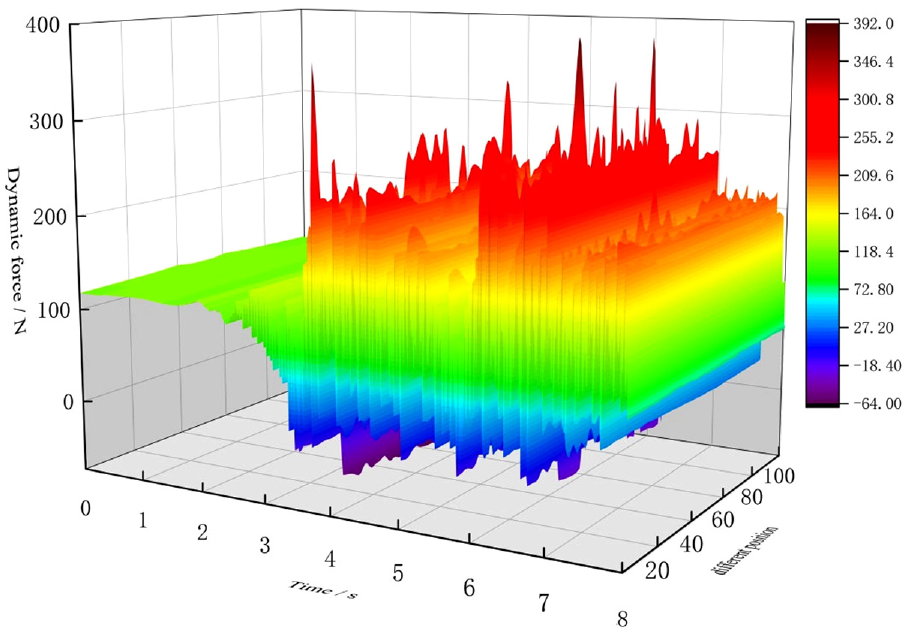
Distribution of the force of the dropper at different times and positions.
It can be seen from the distribution of dropper force at different positions and at different times that there are different axial forces at different positions of the strand at the same time, the stress of the strand unit at the same position is also changing at different times, and the axial force fluctuates greatly after the pantograph passes. When the dropper is in the initial tension state before the pantograph passes, the axial force at different positions of the dropper is stable at about 118.95 N of static tension. When the front and rear pantographs approach the suspension position of the suspension string respectively, the suspension string strand is compressed first, and the suspension string force at different positions decreases gradually. After the pantograph passes through the suspension point at the lower end of the suspension string, the catenary continues to vibrate under the excitation of the pantograph, and the suspension string strand is in the tension between the load-bearing cable and the contact wire. The axial force at different positions also fluctuates centered on the static force, with the maximum value of 390.33 N, which is 3.3 times of the static force of the suspension string, and compared with the maximum value of the dynamic force when the suspension string is equivalent to an integral member, The maximum dynamic force at the local position is 1.8 times of the maximum overall force. The vertical safety factor of the integral hanging string is 2.5. When the maximum local transient axial force is 390 N, the multiplied safety factor is 975 N, which is still less than 1300 N required in China’s railway standard TB/T 2073-2020.
In order to facilitate statistical analysis, the dropper strand is divided into five sections: the upper section of the dropper, the middle and upper section of the dropper, the middle and lower section of the dropper, and the lower section of the dropper, as shown in Figure 18. Each section includes 20 strand units.

Different sections of the dropper.
As can be seen from Figure 17, most prominent peaks in the dynamic force appear in the upper, lower, and middle sections of the dropper.
Extract the maximum dynamic force of 100 units of the whole dropper when the pantograph passes, as shown in Figure 19. It can be found that when the pantograph passes, the maximum dropper force appears in the upper and lower sections of the dropper near the pressure connecting pipe, and the stress in the middle section of the strand is also large. When the rear pantograph passes by, the maximum dynamic force of the dropper appears in the middle section, and there is also a large dynamic force peak in the upper and lower sections. During the whole vibration process, the stress on the middle, upper and lower sections of the dropper strand is relatively uniform, and the maximum value of the dynamic force in the strand unit is also small. The dynamic forces in different sections are counted, as shown in Table 5.

Maximum force of the dropper of each element: (a) front pantograph pass and (b) rear pantograph pass.
Distribution of axial force in different sections of the dropper.

The maximum dynamic force caused by the passing of the front pantograph is 371.17 N, and the occurrence time is 3.77 s. Extract the variation history of the compression amount of the dropper with time, as shown in Figure 20. It can be seen that at 3.77 s, the dropper is in the moment when it is tensioned again from the bending state. Similarly, the maximum dynamic force caused by the passing of the rear pantograph is 390.33 N, and the occurrence time is 6.11 s. the dropper is also in the moment when it is tensioned again. Therefore, it can be found that, the maximum dynamic force of the dropper always occurs at the moment when the dropper recovers from bending to tension after the pantograph passes by.

Compression of the dropper when maximum dynamic force appears.
The minimum value of the dynamic force caused by the passing of the front pantograph is −63.86 N and the occurrence time is 3.74 s. The minimum value of the dynamic force caused by the passing of the rear pantograph is −39.70 N and the occurrence time is 5.86 s. The variation trend of the compression amount of the dropper at the two time points is shown in Figure 21(a) and (b)), respectively. Both of them are the minimum value of the dynamic force in the process of increasing the bending degree, and the minimum value of the dynamic force occurs before the maximum value of the dynamic force.

Compression of the dropper when the dynamic force is minimum value: (a) Compression of the dropper at 3.74 s and (b) Compression of the dropper at 5.86 s.
Conclusion
In this paper, the catenary simulation model and the dropper dynamic force analysis model are established by using the finite element method. The accuracy of the model is verified by comparing with the measured data. Through simulation analysis, the dynamic stress process and law of the dropper when the high-speed train passes through are studied.
A new simulation method that can simulate the catenary and dropper strand is proposed. Combined with the split mold method and negative sag method, the static shape finding analysis of catenary system is carried out, and the actual installation and erection process of catenary is simulated in the modeling process, and the initial model of catenary under ideal working conditions is obtained. The beam-link composite element model is used to calculate the dynamic stress and compression process of the dropper.
By establishing contact pairs between the dropper and the catenary and between the pantograph and the catenary, the dropper, the catenary, and the pantograph are coupled into the pantograph catenary dynamic simulation system, and the effectiveness of the simulation system is verified by comparing the measured lifting amount with the simulated lifting amount.
The dynamic coefficient of dropper is proposed and to characterize the dynamic force of dropper.
The dynamic force of No. 1 and No. 6 droppers is the smallest and the dynamic coefficient is the lowest, while the maximum dynamic force and dynamic coefficient of No. 3 and No. 4 droppers are the highest; The analysis shows that No. 3 and No. 4 droppers are located in the middle of the span and are farthest from the catenary suspension and positioning device, so the vibration is the most intense and the stress fluctuation of the droppers is the largest.
There are different axial loads at different positions of the dropper strand, and the stress state of the same position is also changing at different times. When the front pantograph passes through, the maximum dynamic force appears in the upper section of the dropper, and when the rear pantograph passes through, the maximum dynamic force appears in the middle section of the dropper, up to three times of the static force of the dropper.
The maximum dynamic force of the dropper occurs at the moment when the dropper changes from bending state to tension state after the pantograph passes by. The minimum value of dynamic force occurs in the process of dropper from tension to bending.
Footnotes
Handling Editor: Chenhui Liang
Declaration of conflicting interests
The author(s) declared no potential conflicts of interest with respect to the research, authorship, and/or publication of this article.
Funding
The author(s) disclosed receipt of the following financial support for the research, authorship, and/or publication of this article: This work has been supported by Research Project of China Academy of Railway Sciences Corporation Limited (2021YJ128).