
Abstract
In the paper, a permanent magnet adsorption wall-climbing robot using magnetic particle detection technology for crack detection is introduced, which solves the problems of low efficiency of traditional manual detection and long detection time. According to the working environment of the detection system and the detection functions that need to be completed, the body structure of the robot is designed, the overall size of the robot is smaller than the distance between two steam turbine blades, so it can achieve the crack detection function of large steam turbine blades, and the stability and force analysis of the robot are carried out, and the adsorption conditions that meet the conditions of no sliding and overturning are obtained. In the paper, we use the magnetic circuit method to design a miniature excitation device for robotic applications and use the simulation software Ansoft-Maxwell to verify its feasibility. In the final experiment, it can be shown that the robot designed can achieve a series of functions such as magnetic particle inspection and image acquisition. There is a good prospect for the inspection of turbine blades.
Keywords
Introduction
The development of steam turbines is an iconic symbol showing the country’s comprehensive national strength and technological level. The blades are one of the core components of steam turbines, and the good condition of steam turbine blades is very important. Therefore, regular visual inspections should be performed, and a comprehensive inspection for about 1 month is carried out every 3 years. Around the 1970s, the United States, Germany, and other countries have made relevant statistics on steam turbine accidents. Among them, the accidents caused by blade failures in steam turbine factories accounted for as high as 45%–72%. The Electric Power Research Institute (EPRI) pointed out that nearly 70% of the forced outage of steam turbines were related to blades.1,3
Figure 1 shows two traditional methods of inspecting steam turbine blades. One method is to disassemble the steam turbine blades and move them to the inspection mechanism for inspection. The disadvantages of this method are the safety issues in the process of moving the blades, the long inspection time and the high inspection costs. The other method is that the inspectors carry the inspection mechanism and manually hold the inspection instrument to inspect the leaves. The disadvantage of this method is that the inspectors will experience visual fatigue after working for a long time, and the working conditions are still long, which cannot bring maximum profits to the enterprise. Therefore, there is an urgent need to develop a crack detection robot for steam turbine blades.

Two methods commonly used to inspect steam turbine blades: (a) disassembly inspection and (b) manual hand-held inspection equipment inspection.
At present, Veselá et al. 2 has made a series of summaries on the methods of detecting steam turbine blades, and concluded that ultrasonic crack detection is a better detection technology, but the premise of the conclusion is to disassemble the turbine blades. We are studying two steam turbine blades of 517EWT48 and 117EWT10 provided by Shanghai Electric Power Generation Equipment Co., Ltd., as shown in Figure 2. The steam turbine consists of 51 steam turbine blades. The total blade length is 1523 mm, the bottom width is 380 mm, the end width is 210 mm, and the minimum distance between the two blades is 100 mm. Turbine blades are made of ferromagnetic steel. According to investigations, most cracks occur perpendicular to the leading edge (width 30 mm) and the bottom of the blade. 3 To this end, this paper has researched and developed a magnetic particle inspection robot that can work between all levels of steam turbine blades. Inspectors can perform magnetic particle inspection on large blades that have not been dismantled, which optimizes the drawbacks of traditional steam turbine blade inspection.

Steam turbine blade models 517EWT48, 117EWT10.
Design of magnetic particle inspection robot
Robot overall design
The overall structure of the robot is shown in Figure 3. In order to achieve lightness, the robot body is made of 1 mm lightweight aluminum alloy. In the subject, a total of 4 drive motors are used to drive, there are two industrial cameras in the robot, one is placed inside the robot for collecting crack images, and the other is placed on the front of the robot for video surveillance, navigation and positioning. Among them, a UV lamp module with a wavelength of 385 nm is used to illuminate the cracks in the magnetic particle inspection. At the back of the robot, a fluorescent magnetic suspension liquid catheter channel for magnetic particle inspection is also set up to introduce the fluorescent magnetic suspension liquid. Since the working environment may be in a dark place, two LED lights are used for illumination at the front end of the robot.

The overall architecture of the detection robot.
The excitation device combination in the subject consists of a DC-GA geared motor, a pair of bevel gear combination, a trapezoidal screw, two bearing bases, a screw nut and four excitation devices. The working principle is that when the DC-GA geared motor is spinning, it will drive the bevel gear combination to move, thus completing the rotational movement of the trapezoidal screw, which makes the screw nut pair move vertically downward, and because the screw nut pair is connected to the support frame, it can then complete the vertical downward movement of the four excitation devices and finally the excitation devices are attached to the detection surface.
At the end of the detection process, the DC-GA geared motor is made to reverse, causing the excitation device to reset. The trapezoidal screw in the subject has a self-locking function, because the lead angle (

In the formula, where f is the coefficient of static friction. The overall size of the robot is small, the specific dimensions are shown in Table 1, and the robot has the following advantages:
The robot has a small structure and can detect cracks on large steam turbine blades. Table 1 summarizes the basic parameters of the robot;
There is enough magnetic force to keep the robot in a safe state when working, that is, to prevent the robot from overturning and slipping;
The robot can be adapted to walk on the steam turbine blades;
A miniature excitation device is designed for the detection device of magnetic particle inspection, which can be integrated in the robot.
Parameters of the robot.

Design and analysis of adsorption device
The design of the adsorption device is not only used for the adsorption function of the robot in the entire design, but also can provide an auxiliary magnetic field source for flaw detection. In order to ensure the safety of the robot at work, the permanent magnet adsorption method is the best choice in this topic. According to the optimization of the permanent magnet adsorption device by Gui et al., 4 the adsorption device as shown in Figure 4(a) was designed on the basis of theoretical analysis. The adsorption device in this article consists of a neodymium magnet, a rubber sleeve, and a yoke. Each yoke is attached to the top of the neodymium magnet to form a closed ferromagnetic circuit. The rubber sleeve is used to increase the coefficient of friction so that the robot can overcome obstacles and better protect the neodymium magnet. The simulation of the adsorption device can be seen from Figure 4(b) that the tiny adsorption device can provide 4.24 N suction.

Permanent magnet analysis: (a) the structure diagram of the permanent magnet adsorption device and (b) the simulation analysis of the suction force of the permanent magnet adsorption device.
According to previous studies, in order to ensure that the wall-climbing robot can achieve its adsorption function, it is necessary to establish a force analysis model to determine the necessary adhesion. In the process of magnetic particle detection of steam turbine blades, the robot will have three working states, which are suspended upside down on the blade, inclined to the blade, and vertically adsorbed on the blade. These three working states will be analyzed below.5–8
Adsorption analysis of vertical surface and cantilever surface
Figure 5 shows the three force conditions of the robot. When the robot is adsorbed on a vertical surface, it should be ensured that the robot will not overturn and slip off at point P. According to the force condition, it should meet:

Schematic diagram of force: (a) vertical surface adsorption, (b) cantilever surface adsorption, and (c) adsorption with a certain angle.
In the formula, L is the center distance of the two flat pulleys, Gi is the distance of each adsorption unit from the centroid P, T is the distance of the center of gravity of the robot body (including the load) relative to the vertical wall, from the analysis in Figure 6, the value of T can be obtained, f is the friction force received by the robot, Fi is the adsorption force of each adsorption unit on the wall, Ni is the supporting force of each adsorption unit to the wall, n is the number of adsorption units, and the value of n is 10 in the subject.

The position of the center of gravity of the robot model.
When adsorbing on the cantilever surface, the force analysis is shown in Figure 5(b). The force balance condition of the robot should meet:

Attached to the blade at a certain angle
Figure 5(c) is the force analysis with a certain inclination angle. In order to ensure that the robot will not turn over at P and will not slide, it should meet the following requirements:

In the formula, R is the radius of the synchronous belt wheel, and α is the angle between the adsorption plane and the horizontal plane. Use Solidworks software to determine the center of gravity of the 3D model, then define the corresponding materials in the software. The result analysis shows that the position of the center of gravity is (61.748, 27.141, 33.247), and the approximate values are: X = 62 mm, Y = 27 mm, Z = 33 mm, as shown in Figure 6.
Use the simulation software Maltab to draw the relationship between the maximum adsorption force value and the tilt angle for formula 3, as shown in Figure 7.

Change of angle
It can be seen from the results of the figure that there are extreme points when the inclination angle reaches 47° and 64°, and the maximum inclination angle of 64° is used for analysis. Since the value of n in the subject is 10, it can be seen from the simulation results that the adsorption force of a single adsorption unit is 1.789 N at the extreme point of 64°. Through the robot-related parameters listed in Table 1, substituting the parameters into equations (1) and (2), the maximum adsorption force of the vertical surface and the cantilever surface can be obtained. Through the comparison of the results, it can be finally concluded that the minimum suction force of the adsorption unit developed for this subject should be 1.789 N, and the total adsorption force of the wall-climbing detection robot is 17.89 N. However, it must be considered that the blades will be coated with anti-corrosion coatings when they operate for a long time in harsh environments. Therefore, an anti-corrosion coating gap must be added. Usually the thickness of the anti-corrosion coating is 1 mm, and the Ansoft-Maxwell software can further simulate the change of the air gap height and the size of the adsorption force.
The simulation results show that when the adsorption device is close to the steam turbine blade without air gap, the suction force of the adsorption device is 4.24 N, which is in line with the conclusion in Figure 4(b).
When the air gap length is increased to 2.0621 mm (including the thickness of 1 mm anti-corrosion coating), the suction force of the adsorption device is lower than the design standard value of 1.789 N. The simulation results can be seen in Figure 8. Therefore, when the air gap is greater than 2.0621 mm, the robot will have safety issues during crawling. Through the above design of the permanent magnet structure, the adsorption force of the adsorption device can meet the design requirements.

Force and air gap changes.
Design and optimization of excitation device
In this paper, a cross-pass magnetization method is applied to magnetize the workpiece to be inspected, which is simple to operate, time-saving, and easy to automate. 9
The working principle is to generate a rotating magnetic field through two intersecting π-shaped electromagnetic yokes. The sinusoidal alternating magnetic fields generated by the two electromagnetic yokes change with time to form an elliptical rotating magnetic field. The cross yoke is shown in Figure 9.
Planar cross yoke method.
Due to the constraints of the overall size of the robot, the design of the excitation device has also been affected to a certain extent. For the design of a single excitation device, the overall size should not exceed (35 × 30 × 25 mm). If the excitation device with a smaller size has sufficient remanence capacity, the first consideration is to use direct current, which has better remanence capability than alternating current. The design of this shape is wide and long, which is more conducive to heat dissipation. The article proposes a miniature excitation device that can meet the function of magnetic particle flaw detection. Its structure design is as follows.
The inner diameter of the shell is designed to be about two to three times the diameter of the core, so considering its structural design, the inner diameter D2 of the shell is 24 mm; the armature working stroke δ is set to 2 mm, and the working voltage is 28 V; according to Zou and Li 10 research on iron core materials, industrial pure iron DT4 is selected as the iron core material in the article. Formula 4 is used to calculate the relevant size parameters of the coil.

Where bk is the coil thickness, dc is the armature diameter, the armature diameter is set to 12 mm in this article, Δ is the coil bobbin and its insulation thickness, Lk is the coil length, and β is the ratio of the coil height to the coil thickness. This value can be taken as 3.4.
According to the designed coil size and shape, the electromotive force IW, the number of coil turns W, the wire diameter d and the suction force F required to meet the conditions can be determined.

Among them, Dcp is the average diameter,
Electromagnet structure parameters.

In the calculation process, the ferromagnetic resistance and leakage flux are ignored. Gz is the magnetic permeability, Φ is the magnetic flux in the air gap, and S is the cross-sectional area of the iron core. Through verification, it can be concluded that a single excitation device can lift an object of 9.65 kg. The structure of excitation device can be seen in Figure 10.
Excitation device structure.
Control system
Power supply circuit
In this system, a 12 V lithium battery is used to power the entire system. In order to reach the 5 V working voltage of the Raspberry Pi Zero W and motors, use the MP1584 chip to convert the 12 V to output a 5 V to meet the working requirements. Figure 11(a) is a circuit diagram of the 12–5 V power supply circuit.

Control principle diagram: (a) power supply circuit, (b) drive circuit for drive motor and GA geared motor, and (c) drive circuit for water pump and excitation device.
Drive circuit for drive motor and GA geared motor
The drive motor circuit uses the TB6612FNG chip as the drive chip. TB6612FNG is a DC motor drive device. It has a high-current MOSFEST-H bridge structure, dual-channel circuit output, and can drive two motors at the same time. This robot adopts the form of two DC gear motors in parallel for each circuit to realize the four-wheel motion of the robot. The power supply of the motor drive chip is a 12 V–5 V power supply form provided by the power management circuit of the drive board, and the drive power supply also uses 5 V power supply. The signal control port Y is connected to the IO port of the Raspberry Pi ZeroW, which is used to provide the forward and reverse logic control signals of the DC gear motor and the PWM waveform control signals of the two motors. The GA geared motor in the subject also uses the TB6612FNG motor drive chip. The motor drive chip is shown in Figure 11(b).
Drive circuit for water pump and excitation device
This robot uses DC 12 V to control the micro water pump and the micro excitation device. The water pump selected in the subject has a built-in miniature DC motor, and the internal vacuum is formed by the movement of the motor to extract the fluorescent magnetic suspension to complete the magnetic powder spraying function. In the module design, a high-level signal is used to control the switch of the circuit, so as to realize the work of the 12 V miniature water pump and the micro excitation device. Figure 11(c) is a schematic diagram of the circuit for high-level control of 12 V output.
Magnetic particle inspection process and the robot motion track
The automatic magnetic particle inspection process is as follows:
After the robot is adsorbed on the steam turbine blades and receives the instruction of automatic detection, the water pump starts to work. In the experiment, the start of the water pump is realized by voltage change, and the flow control is realized in a closed loop. The water pump is driven by high voltage, and then a slow flow rate is obtained by reducing the pressure. In this way, the gas in the water pipe is compressed and the magnetic suspension is filled in the water pipe, it takes 6 s to perform this process.
After the magnetization work, the GA geared motor drives bevel gear combination to rotate, so that the excitation device combination can move in the vertical direction, and finally the excitation device is close to the working surface to prepare for the magnetization work. After passing the experimental verification, the GA geared motor works for 2 s, and the magnetization device combination will be close to the working surface.
After the GA geared motor completes the action, there will be a 2 s delay, after which the excitation device will undergo a cross yoke method process. During the magnetization process, the water pump will synchronize with the working time of the excitation device. L1 and L2 coils are energized firstly, and 12 V will be applied first for 3 s, after a delay of 1 s, the coils L3 and L4 are being energized, and the 12 V is still applied for 3 s to complete their magnetization work. The working principle is shown in Figure 9.
After the completion of the magnetization work, the GA geared motor will reverse, slowly raise the excitation device to the original position, and complete the resetting work. At the same time, when the drive motor is operating, the camera starts imaging, and the robot will move forward 11 mm so that the crack is directly below the image collection camera, and the camera performs image collection.
The above steps should be repeated to complete the continuous autonomous detection operation process until the stop signal is received. After receiving the stop signal, the robot will complete the detection of the current position and then terminate the entire detection process. Figure 12 shows the operation of each part of the robot during the magnetic particle inspection process. It can be seen from the figure that the entire inspection task cycle is 19 s, and each component performs its task in a closely connected manner during the inspection process.
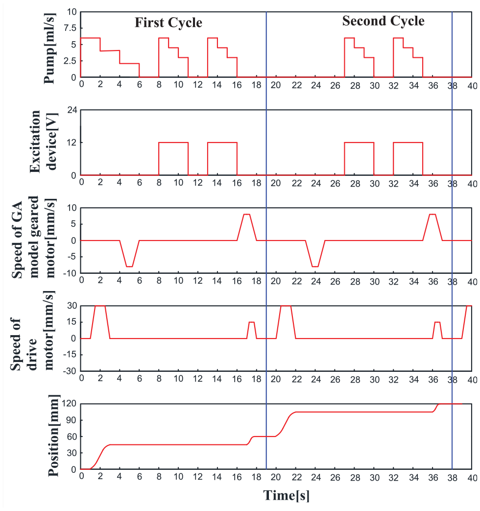
Changes in the speed and displacement of the robot motor.
It is necessary to emphasize the motion track of the robot on the inner arc as well as on the back arc of the turbine blade, because they are slightly different from each other. As shown in Figure 13, the motion track of the robot on the inner arc of the turbine blade as well as on the back arc is accomplished in seven steps, and the inspection process both start from the root of the turbine blade and finally return to the root, thus completing the robot traversal.

Motion track of the robot on the turbine blade: (a) motion track of the robot on the back arc of the turbine blade and (b) motion track of the robot on the inner arc of the turbine blade.
Experiment
In the following, we will conduct adsorption experiments on the robot at different positions of the steam turbine blades and verify the practicability of the excitation device in the subject, and verify the robot’s motion stability and magnetic particle detection capabilities through experiments. The experimental environment is composed of steam turbine blades and a flaw detection robot system, as shown in the experimental environment in Figure 14.
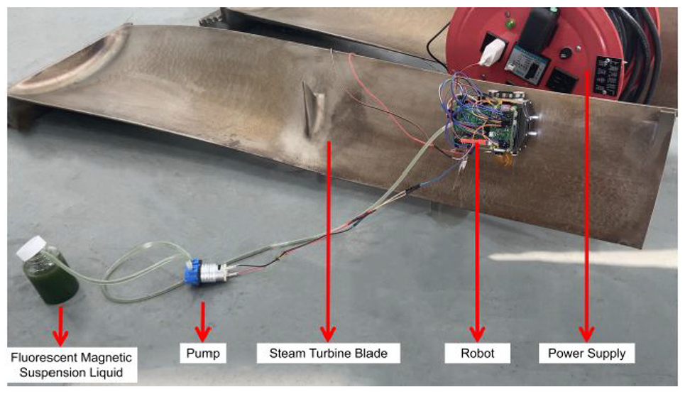
Experimental environment.
The flaw detection and inspection robot system mainly includes the inspection robot body, water pump, power supply, and computer. The operator can control the computer to complete the realization of the robot’s various functions, and it is divided into automatic flaw detection and single-step control flaw detection, which can be adjusted according to different environments. The computer can also observe the crack image in real time, and store and post-process the image, so that the robot can replace the manual inspection work.
Adsorption stability test
Steam turbine blades have a certain curvature. For this reason, it is necessary to verify the practicability of robots in different positions of steam turbine blades.
The first series of experiments is to conduct experimental tests on the back arc of the blade of the steam turbine blade. Due to the maximum curvature of the back arc, it may cause the problem that the adsorption device cannot be adsorbed. Find the point of maximum curvature through the software (Figure 15(a)), and conduct experimental verification. Figure 15(b) shows the stability test of the robot at the point of maximum curvature. After many stability experiments there, there is no slipping or rollover phenomenon, indicating that the robot has a stable suction at the maximum curvature. In the same way, many experiments are carried out on the back arc surface, and the movement can be stabilized. It is proved that the robot can work safely on the back arc surface of the steam turbine blade.
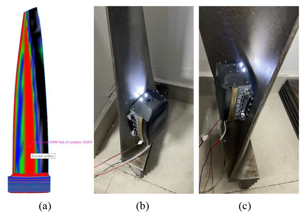
Adsorption stability test: (a) the maximum curvature of the back arc of the steam turbine blade, (b) adsorption experiment at the maximum curvature of the back arc surface of the steam turbine blade, and (c) the adsoption stability test of the robot at the largest concave surface.
The second series of experiments is to test the inner arc of the blade profile of the steam turbine blade. The most important thing is to conduct the robot adsorption stability test at the largest concave surface where safety problems are most likely to occur. As shown in Figure 15(c), it is a test of the suction stability of the robot at the largest concave surface. Through multiple walking tests of the robot here, there is no slipping and rollover phenomenon, which proves that the robot has a stable suction at the largest concave surface. Stability tests were also carried out at other positions on the inner arc of the steam turbine blade. The adsoption device was stably adsorbed on the working surface during driving, which proved that the robot can work safely on the inner arc of the steam turbine blade.
On the whole, the robot developed in the subject has the ability to operate stably on the blade shape of the steam turbine blade. However, the robot developed in the subject is only suitable for medium and large steam turbine blades, and not suitable for steam turbine blades with large curvature.
Excitation device test
In subsection 2.2.3, the excitation device is designed and calculated preliminarily, and the lifting force requirements of the excitation device in the magnetic particle inspection can be realized through the design calculation. The following will use simulation software to further determine the feasibility of the device, it can also be seen from the simulation results in Figure 16 that the excitation device can lift objects of 194.06 N, which meets the requirements of magnetic particle inspection technology for the lifting force of the excitation device.
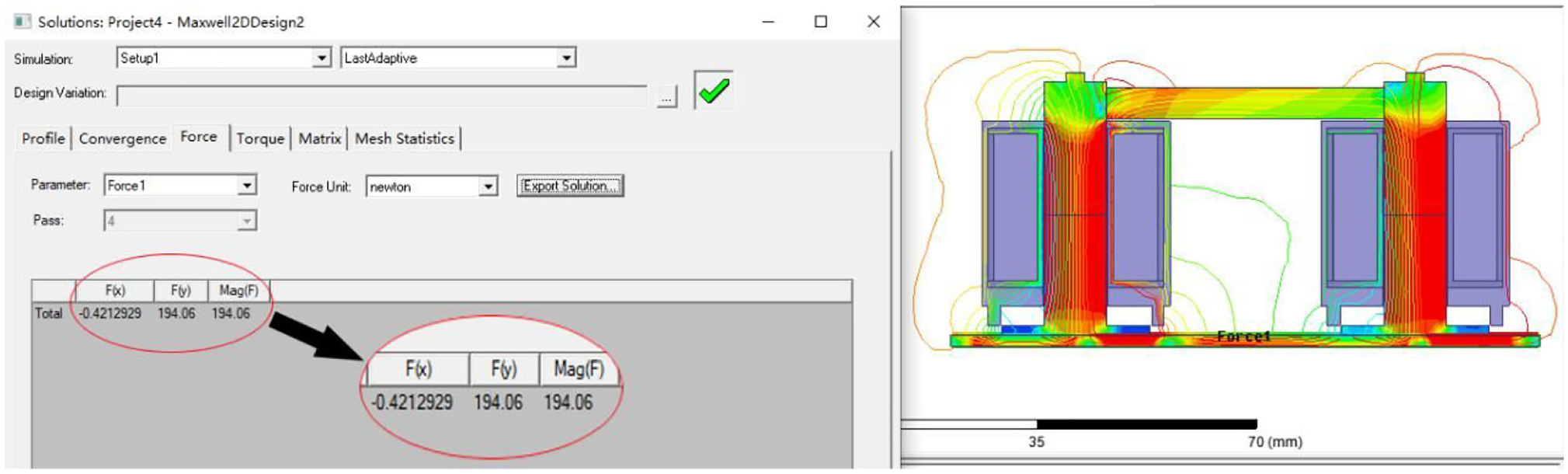
Simulation diagram of lifting force of excitation device.
Comparison of magnetic field simulation with and without defects
The magnetic field intensity was compared with and without defects after the excitation device was fed with a current of 0.15 A. Figure 17(a) shows the magnetic induction density cloud when there is no crack on the inspection surface, and the result shows that the magnetic field is uniformly distributed in the inspection area. Figure 17(b) shows the magnetic induction density cloud when there is a crack with a width of 2 mm on the inspection surface, and it can be seen that there is a leakage deformation phenomenon at the crack and the magnetic field gather at the crack, which proves that the fluorescent magnetic suspension penetrate into the crack under the action of the excitation device and finally achieve the effect of magnetic powder gathering. The comparison between Figure 17(a) and (b) also shows that a larger flux density can be detected without cracks, which is the result of flux leakage.

Magnetic induction density cloud: (a) magnetic field density cloud when no cracks are present and (b) magnetic induction density cloud when there is a crack with a width of 2 mm.
Figure 18(a) shows the simulated results of magnetic flux lines when the excitation device is connected to a current of 0.15 A to detect the surface without cracks, and it can be seen from the results that the magnetic flux lines is almost symmetrical, and the reason for the incomplete symmetrical may be that the size and parameters of the excitation device have an effect. Figure 18(b) shows the results of magnetic field simulation when there is a crack, and it can be seen that there is a clear phenomenon of magnetic field change at the crack, which further verifies that there is an aggregation of magnetic field at the crack, which can cause the fluorescent magnetic suspension to pool at the crack.

Distribution of magnetic flux lines on the specimen: (a) simulation results of the magnetic flux lines without cracks and (b) simulation results of the magnetic flux lines with cracks.
Walking stability analysis
Motion model modeling and simulation analysis
The equations of motion for the vertical motion on the cantilever plane as well as for the movement on the horizontal plane are established, the formula is as follows:

In the above formula, M is defined as the total mass of the detection robot in the subject, F1 is the driving force of the motor, c is the damping of the robot when it moves, and the value in the subject is 20 N (m/s), f is the sliding friction force when the robot moves, G is the total weight of the robot;
Simulink simulation software is used to study the instantaneous acceleration and velocity variation of the robot to verify the rationality of the motion and the stability of the motion. Figure 19 is the simulation model diagram.

Kinematics simulation model of the robot in three poses.
Analysis of robot stability simulation results
Figure 20(a) shows the acceleration change image of the robot when the robot is started instantly under three working conditions. The blue line represents vertical downward movement model, the red line represents vertical upward movement model, and the purple line represents adsorption analysis of cantilever surface. It can be seen from the figure that the acceleration can reach 0.24 m/s2 at instant start in the case of vertical downward movement, in the case of vertical upward movement, it can reach 0.16 m/s2, and in the case of suspended upside down on the blade, the acceleration is 0.07 m/s2. It can be seen that the robot will have a short shock when it starts, but due to the existence of damping during the movement, it will eventually reach a balanced movement state within 4 s.

Analysis of robot stability simulation results: (a) motion acceleration diagram of the robot in three poses and (b) motion velocity diagram of the robot in three poses.
Figure 20(b) shows the movement speed diagram in three different poses, it can be seen from the figure that the three different motion states will stabilize within 3 s. When moving vertically upwards, the speed will eventually tend to 0.05 m/s, when moving vertically downwards, the speed will eventually tend to 0.074 m/s and when suspended upside down on the blade, the speed will eventually tend to 0.025 m/s. The speed simulation can also further illustrate the stability of the motion system.
Figure 21 is an experiment of applying the robot to the walking stability of the steam turbine blades to test the walking stability of the robot on the inner arc and the back arc of the blade.

Robot performs walking stability test on steam turbine blades: (a–d) shows the stability test of the inner arc of the blade and (e and f) shows the stability test of the back arc of the blade.
Automatic detection test
The designed inspection robot can perform a complete magnetic particle inspection function on the inspection surface, as shown in Figure 22(a), it can realize the adsorption function, the crawling function of the detection robot, the magnetization function, the function of spraying the fluorescent magnetic suspension, the luminescence of the ultraviolet light-emitting diode and the image acquisition function. Figure 22(b) shows the crack images collected by the camera when different currents (0.1, 0.15, and 0.2 A) are applied to the excitation device, and the cracks appear obvious under the irradiation of ultraviolet light-emitting diodes.

Continuous test results: (a) the on-site simulation robot travels during the steam turbine blade and (b) test results of 0.1, 0.15, and 0.2 A are input from top to bottom.
The following further explains that the robot developed by this paper can complete the crack detection function, and will compare the results of artificial crack detection and robot crack detection. Figure 23(a) shows the result of manual inspection of the crack image, and Figure 23(b) shows the result of the crack detection image of the inspection robot. It can be seen that after the comparison between the manual detection result and the robot detection result, the detection effect is roughly the same, and potential cracks can be detected.

Comparison of crack detection effect: (a) manual inspection of the crack image and (b) crack image collected by the robot.
In order to further illustrate the ability of the robot developed by our subject to detect cracks, the A1 test piece is used for experimental detection. Figure 24(a) is the experimental environment, Figure 24(b) is the image result collected by the detection robot, the A1 test piece (15/50 μ) is glued to the surface of the steam turbine blade by means of hot melt glue, and turns blue under the irradiation of an ultraviolet lamp. In Figure 24(c), the outline of the A1 test piece can be clearly seen, which also confirms the actual effect of the robot’s magnetic particle inspection. It can be seen that it is almost the same as the result detected by the large-scale detection system, indicating that the developed robot meets the requirements of magnetic particle detection and can achieve efficient and autonomous detection.

Robot sensitivity test: (a) experimental environment, (b) the result of the robot collecting the image of A1 test piece, and (c) experimental results.
Discussion and conclusion
We have developed a miniature inspection robot for magnetic particle inspection of steam turbine blade cracks. In this paper, the permanent magnetic adsorption method is used to solve the problem of safe operation of the robot adsorbed on the surface of the steam turbine blade.
In order to ensure the safe operation of the robot, the adsorption device is designed and optimized and the mechanical analysis of the robot under different working conditions is carried out. In the process of magnetic particle inspection, the lifting force of the excitation device needs to be tested first, and the crack detection is performed after the inspection requirements are met. A new type of excitation device is designed and integrated into the robot. The rationality and practicability of the structure are further confirmed by simulation software. Combined with the Raspberry Pi to transmit information at a high speed, real-time, highly synchronized coordinated control is realized. This flexible detection method solves the close cooperation between the spraying of the fluorescent magnetic suspension, the magnetization function of the excitation device on the blade, and the crack image collection and other operations, and achieves efficient detection.
The test results of the robot show that this new type of magnetic particle inspection robot developed for crack inspection of large steam turbine blades can achieve stable inspection work and solve the problems of low inspection efficiency and high inspection cost.
Footnotes
Handling Editor: James Baldwin
Declaration of conflicting interests
The author(s) declared no potential conflicts of interest with respect to the research, authorship, and/or publication of this article.
Funding
The author(s) disclosed receipt of the following financial support for the research, authorship, and/or publication of this article: Supported by the project of Shanghai multidirectional die forging Engineering Technology Research Center (20dz2253200).