
Abstract
This paper presents a wall-climbing robot which can stably hold and move on the ground-wall surface. The robot uses propeller reverse thrust as an adsorption force and can adapt to the surface of several media materials. The influence of the robot’s structural parameters on its power system is analyzed by comparing a single power system test and a robot prototype power test. A structural analysis of the robot is performed under two specific situations; when he is in transition from the ground to a small slope, and when he is on the slope. The force state of the robot is then obtained in different conditions. Experimental results show that the adjustment range of different rotor inclination angles of the robot, the width of the fixed rotor plate and the different near-ground distances, affect the traction of the robot. The robot motion performance and adaptability under different ground/wall environments are analyzed, by conducting the robot climbing experiment under a small slope, a vertical wooden wall surface and a vertical indoor wall surface. Stable adsorption and optimization tests are also performed. Moreover, the stability of the robot’s motion is verified. Finally, a theoretical and experimental accumulation is laid for the realization of the smooth transition of the robot from the ground to the wall.
Introduction
Wall-climbing robots can replace humans in performing dangerous tasks in several environments. The research on wall-climbing robots has become crucial in the field of robotics. 1 This is due to the fact that more people are interested in wall-climbing robots in several civil and industrial application domains,2–5 such as bridge inspection, inspection and maintenance of large oil storage barrels in petrochemical industry, welding, sandblasting for rust removal, painting and anti-corrosion treatment on ship hull, spray painting and anticorrosion treatment, and cleaning of glass outer walls of high-rise buildings, etc.
Generally, this type of robot uses wheeled locomotion mechanism to achieve higher movement speed. The main adsorption methods are; vacuum or negative pressure suction, reverse thrust, magnetic adsorption, and bionic adhesion. Vacuum negative pressure robots are widely used on relatively smooth walls in order to clean glass-walls. However, air in the robot’s suction is prone to leakage when the robot is on the walls. There are also some large devices on the wall surface, forming obstacles that the robot has difficulties to cross.6,7 The magnetic wall-climbing robot can be used for non-destructive inspection of the inner and outer surfaces of large metal vessels and huge tanks. However, it can only be used on the wall of magnetically conductive materials.8–11 The bionic adhesion wall climbing robot is mainly used in the case of bonding bionic materials and hooking imitating animal hooks.12–16 In fact, the bionic materials research cost is high, the adhesive material cannot be cleaned by itself, and it is easy to desorb during use. If the hooking structure is adopted, the drive control of the robot mechanism will be complicated.
In the past decades, several researches on anti-thrust wall adsorption robots, that is, adsorption based on the reverse effect of propeller lift, have been carried out.17–22 For instance, Tanaka et al. 23 developed an anti-thrust wall climbing robot for adhering on outdoor external wall. The ROPE RIDE robot 24 was developed by Seoul University of the Republic of Korea, by adopting the crawler movement mode. The motion speed of the robot can reach 15 m/min with a load of 20 kg. Alkalla et al.25,26 developed EJBot I and EJBot II. These robots have a hybrid drive system and a good adhesion performance. They can be used for a variety of vertical walls. Shin et al.27–29 used a multi-axis rotorcraft to rotate 90° and attach to the wall, after lifting off from the ground. Due to the use of the rotor mechanism for the flight attachment motion, the required robot control accuracy, during motion, is high.
In general, wall surfaces that do not contain bulges, slots or dirt, are suitable for robots to climb. Therefore, vacuum suction robots, magnetic robots, and bionic robots can be used. However, in real applications, several obstacles and limitations prevent the wall-climbing of the robot. Therefore, the developed robot should be able to cross some obstacles and should have a high movement speed. This paper presents a new wall-climbing robot that switches from one side to the other side of the climbed outer wall of the underlying building. The designed robot has a double-propeller as a reverse thrust allowing him to float and to steadily move on the wall surface. In order to demonstrate that the robot can stably adsorb on a variety of media walls, a prototype verification and analysis process, similar to that of the “VERTIGO robot,” 20 was carried out. The stability of the robot’s motion was analyzed in terms of its structural parameters and control system. The functioning principle of the developed robot is similar to that of the “VERTIGO robot,” but the final prototype can achieve completely different goals, as will be shown in the sequel.
Firstly, in order to make the robot move fast, the wheel structure and the electric system are established. In order to analyze the difference between the theoretical value of the robot dynamic system and the actual measurement result, a single dynamic drive system and a horizontal adsorption force experiment are designed. The static analysis of the robot is then discussed, in two specific scenarios; when he is in transition from the ground to a small slope, and when he is on the slope. The feasibility of the robot structure is tested when the robot moves on a small sloping wall. The motion experiments on vertical wooden walls and indoor walls demonstrated that the robot can achieve a stable adsorption on a variety of vertical walls. Moreover, we show that, by improving the robot system, it can initially achieve stable adsorption and movement in a certain area. Finally, the tests and experiments demonstrate that the designed robot is a good foundation to adsorb and stably move on the outer walls of the buildings.
Robot design
The weight of the robot body is 2.5 kg. It mainly consists of a supporting platform frame, four wheeled systems, two rotor power systems, a control module, and a communication module. The structure prototype of the robot is shown in Figure 1. The supporting platform frame is composed of carbon fiber plates and honeycomb material. Two 1200 KV brushless motors and two 10″ diameter propellers are used as a drive system so that the robot can hold and move stably on the wall. The drive system is installed on the fixed plate of the rotor. The tilt angle of the rotor is adjusted by the steering gear, which is fixedly installed on the rotor fixed plate. The 4000 mAh battery is used to ensure that the robot has a certain endurance and a sufficient power supply. To avoid the influence of aerodynamic disturbance on the rotor, the front rotor rotates clockwise, while the rear rotor rotates counterclockwise. Both the front and rear rotors generate reverse thrust so that the robot sticks to the contact surface. The robot adheres to the contact surface under the action of the reverse thrust, which is generated by the front and rear rotors.
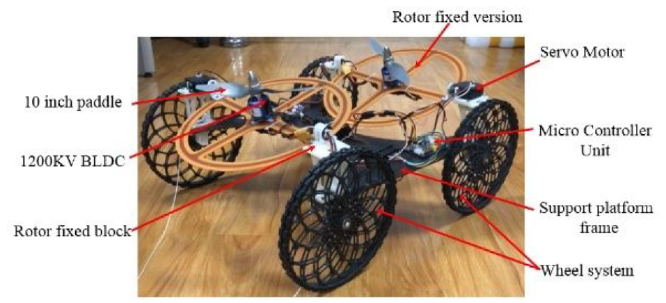
The structure prototype of the robot.
The robot moves forward and backward under the combined action of changing the inclination of the rotor platform and adjusting the propeller speed. The wheel flange is equipped with soft tires, in order to increase the friction with the contact surface. The structure parameters of the robot are shown in Table 1.
The robot structure parameters.

Robot power arrangement
In robotics design, the parameters used to select the drive system often differ from those of the real application process. In fact, it is necessary to test and measure the rotor power in order to obtain the actual reverse thrust. The instruction of the rotor reverse thrust is generated by the controller through the Pulse Width Modulation (PWM) signals. The electronic governor adjusts the motor speed according to the pulse width, while the blades are installed on the motor output shaft to directly generate the reverse thrust. The aerodynamic forces and moments are computed by combining the momentum with the blade element theory. 30 By ignoring the resistance and the lateral moment of the propeller, a single power unit produces the reverse thrust F and the torque Q. Both the reverse thrust and the torque are proportional to the square of the rotational speed. 31
The following assumptions are made in order to simplify the model: (1) The robot is absolutely rigid so that its structure and elastic deformation are negligible, the position of its center of gravity remains unchanged and its mass is constant. (2) The air is an incompressible ideal fluid and has no viscosity. (3) The blade is an infinitely thin disk that acts uniformly in the air when it rotates. (4) The ground is an inertial reference system, that is, an inertial coordinate system. The reverse thrust and the torque are computed as:


where CF and CQ are respectively the pull coefficient and the torque coefficient of the rotor, ρ is the air density, A = πR2 is the area of the propeller, R is the propeller radius, ω is the angular velocity of the propeller, k is the lift coefficient and d is the torque coefficient. Based on the above assumptions, ρ, A, CF, CQ, and R are fixed values.
It can be seen from equations (1) and (2) that both lift and torque are proportional to the square of the angular velocity, while in actual control, the change in blade speed is positively related to the current. To test the rotor reverse thrust, a device (Figure 2) that includes a battery, an electronic tension dynamometer, a DC brushless motor, a propeller, an electronic governor, a receiver and a remote control, is used. As for the error caused by the gravity of the drive system, a level meter is used to measure the horizontal reverse thrust. The actual traction force of a single drive system is finally obtained.
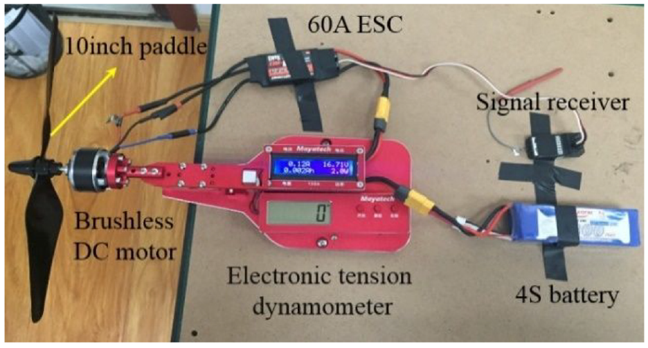
Motor power reverse thrust test device.
The robotic power unit is equipped with a 10″ diameter propeller, within the maximum current adjustment range. The propeller can generate reverse thrust by adjusting the forward and reverse rotation of the brushless motor and the forward and reverse installation of the blades. The propeller installation method is shown in Figure 3. The front and rear propellers rotate in opposite directions in order to reduce the aerodynamic disturbance between them. The front and rear propellers are reverse rotation and positive rotation propellers, respectively. They are installed upside down on the output end of the brushless motor.

The 10″ propeller installation.
The reverse thrust test curve of the propeller is shown in Figure 4. The instruction of the rotor reversal thrust is generated by the controller using Pulse Width Modulation (PWM) signals. It can be seen from equation (1) that the propeller thrust is proportional to the square of the motor speed, while the square of the speed is proportional to the pulse width. During the measurement process, the PWM value has a small range of display change. The current value, changing in real time, is used as the symbol abscissa in order to clearly reflect the change trend of the reverse thrust. Note that the tensile force measurement instrument, shown in Figure 2, is able to measure the current and the magnitude of the reverse thrust, in real time. It can be seen from Figure 4 that the magnitude of the reverse thrust increases with the increase of the current value. The maximum reverse thrust is 25 N for a current value of 50 A. When the reverse thrust reaches its maximum value and the PWM continues to increase, the blade speed and the power value, flowing through the tension measuring device, no longer change.
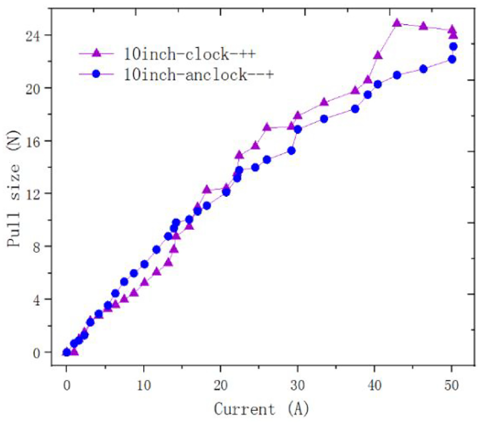
The 10″ propeller reverse thrust curve.
Robot power system test
The experimental device, shown in Figure 5, is used to measure the actual adsorption force of the double-propeller reverse thrust robot. More precisely, the whole robot is horizontally placed on a high precision measurement balance. The rotor is also placed in the horizontal position. The value displayed on the electronic balance is recorded by adjusting the speed of the front and rear propellers.

Adsorption force testing device, in horizontal position.
A comparison between the actual measured adsorption force curve and the theoretical data curve is shown in Figure 6. The actual adsorption force is measured when the rotor platform is adjusted to the horizontal position, after the power unit is installed on the robot. The theoretical data computation is based on the single pull value that is two-times measured using the motor power reverse thrust device. It can be seen from Figure 6 that the increase of the robot horizontal adsorption force, depends on the blade speed. The growth of the curve is positively correlated with the current value when it is less than 40 A. It can be deduced from Figure 4 that, with the front and rear double-propeller, the theoretical adsorption force of the whole robot should be 50 N. However, the maximum adsorption force achieved by the actual robot is 35.96 N, as shown in the experimental test results, in Figure 6. The actual measured value of the adsorption force is only 72.27% of the maximum value, while the adsorption efficiency is diminished by 27.73%.
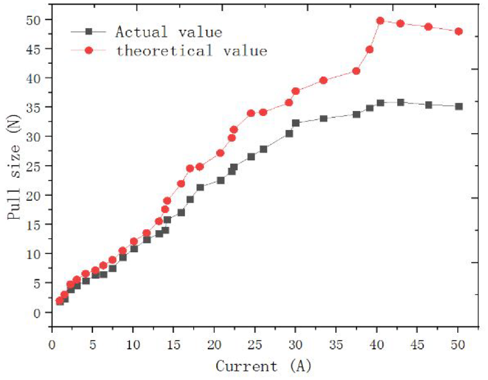
Comparison between the actual measured adsorption force and the theoretical data.
This is mainly due to the loss of the air velocity generated by the structure of the rotor fixing plate, on the bottom of the propeller. In future work, we aim at optimizing the robot structure in order to improve its actual adsorption efficiency.
Robot static analysis
In order to study the robot movement from the ground to the wall, two motion states should be analyzed; when he is in transition from the ground to the small slope, which is also referred to as “uphill state,” and when he is on the small slope. The force diagram of the reverse thrust wall climbing robot in uphill state is illustrated in Figure 7. When the robot is moving, the front wheels are lifted by the combined action of the turning rotor and the reverse thrust of the rear propeller.

Force diagram of the robot in uphill state.
In Figure 7, the XO1Y coordinate system is used, where the origin is the center point of the driving wheel O1, the X axis is the horizontal line and the Y axis is normal the X axis and passes by O1. The uphill state static model of the robot is given by:

where FNi is the normal force acting on wheel i, Ffi is the frictional force acting between wheel i and the contact wall, F1 and F2 are respectively the reverse thrust generated by the front and rear rotors, α1 and α2 are respectively the tilt angles of the front and rear rotors (i.e. the elevation angle of the rotor and the robot), β is the inclined angle of the small slope, γ is the angle between the robot plane and the horizontal plane, m is total weight of the robot, R is the wheel radius, C is the position of the robot center of mass, LC is the distance from the robot center of mass to the axis of the rear wheel, L is the distance between the center axis of the front and the rear wheels.
Note that the force direction is perpendicular to the blade mounting fixing plate. The force analysis of the robot motion state, after he completely moved from the ground to the inclined slope, is shown in Figure 8.
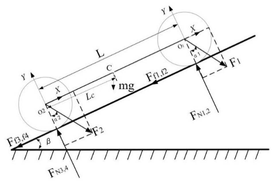
Force diagram of the robot on the slope.
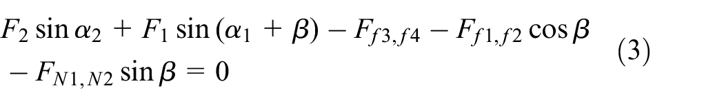
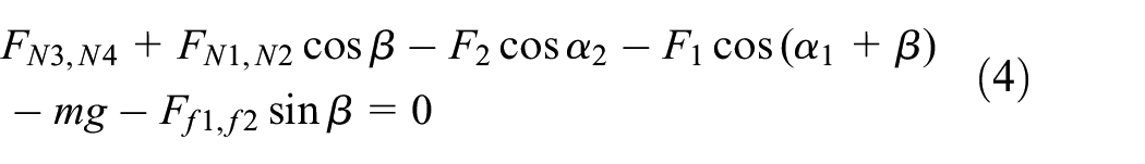
The static model of the robot, when he is on the slope, can be expressed as:

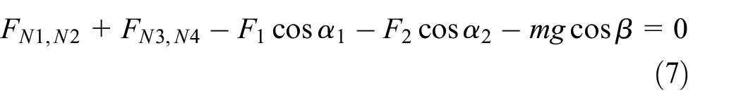

When angle
Since the model represents a statistically indeterminate problem, the force displacement method is used for compatibility, while considering the chassis as a rigid body, so that the final equation is expressed as:

where kwi is the stiffness of wheel i. When the robot is in a static equilibrium state, the frictional force Ffi should always be less than the normal force FNi multiplied by the static coefficient of friction


Experiments and discussion
Effects of different frequencies of rotor inclination angles on the robot performance
The inclination angle of the robot rotor can be rotated from 0° to 360°, so that the robot moves more smoothly, while the motion state can be controlled in real time. In the actual control operation, the inclination angle of the rotor can be changed by a single angle or by multiple angles. To study the influence of the rotor inclination angle change on the robot motion performance when he is in the horizontal state, we set the increase of the rotor inclination to a single or five angles.
The experimental results are shown in Figure 9. The black curve represents the horizontal traction recorded when the rotor tilt angle is increased by 5°, with a single degree increment. The red curve represents the horizontal traction when the rotor tilt angle is five times increased. It can be clearly seen that the horizontal traction of the black curve is significantly higher than that of the red curve. The robot’s horizontal traction is greatly affected by the rotor tilt angle adjustment. The robot propeller speed is set to 30% of the maximum velocity in order to reduce the experiment risk.

Traction curve with different frequency rotor inclination angle changes.
It can also be observed from Figure 9 that the horizontal traction force of the robot increases with the increase of its inclination. When the tilt angle of the rotor increases by 1°, the horizontal traction is significantly higher than the one obtained when the rotor is five times increased. Therefore, it can be concluded that the robot performance with 1° change of the rotor inclination angle is higher than its performance with multiple times rotor inclination angle change. This lays a good foundation for the subsequent movement of the robot on the actual outer wall.
Influence of the propeller-to-ground distance on the robot performance
The rotor of the dual-propeller robot is located near the ground. Under the action of the high-speed rotation of the propeller, the airflow above and below the propeller blades is accelerated, which promotes the change of the propeller’s reverse thrust.
Studying the propeller-ground effect of the robot propeller is crucial for the stability control of the whole robot. In the actual test measurement, the robot horizontal traction is tested when the height of the fixed rotor block is set to 65, 55, and 45 mm. Note that the rotor fixed plates have a width of 13 mm. The rotor fixed block of the robot is shown in Figure 10.

Rotor fixed block, used in the experimental test.
The horizontal traction force curve of the robot at different propeller-ground distances, is shown in Figure 11. The propeller speed is set to 30% of the maximum velocity during the experiment in order to reduce the risk. It can be seen from Figure 11 that the robot horizontal traction force gradually increases when the rotor inclination angle is greater than 10°. When the rotor tilt angle increases to 65°, the horizontal traction force no longer increases. It can also be seen from the traction force curve that the robot has different growth rates of horizontal traction force, at different propeller-ground heights. The growth rate of the traction force and the maximum traction force reach their maximum values for a distance of 55 mm. The growth rate of the horizontal traction force and the maximum traction force, for a propeller-to-ground distance of 45 mm, are the lowest. The results also show that the fixed blocks of the rotor, at different propeller-ground distances, have a large influence on the horizontal traction of the robot. The rotor inclination angle is between 15° and 65°, while the height of the rotor block has the largest influence on the robot’s traction.

Traction curve at different near-ground distances.
Effect of the rotor fixed plate width on the robot performance
The rotor fixing plate directly affects the motion performance of the robot due to the fact that it is installed under the DC brushless motor, and the air flow in the area under the propeller is not blocked. To study the influence of the rotor fixed plate width on the robot motion performance, 13 and 22 mm wide rotor fixed plates are used, while fixing all the other structure parameters. The installation structure is shown in Figure 12. The robot horizontal traction force is measured to study the influence of the rotor fixing plate width on the aerodynamic characteristics of the upper and lower surfaces of the propeller, and on the overall robot motion performance. The propeller velocity is set to 30% of its maximum value to reduce the experiment risk.

Structure of the robot with different rotor fixed blades: (a) 13 mm wide rotor fixed blade and (b) 22 mm wide rotor fixed blade.
Figure 13 illustrates the measured horizontal traction of 13 and 22 mm wide rotor fixed plates, for a rotor fixed block height of 65 mm (a), 55 mm (b), and 45 mm (c). It can be seen that the robot horizontal traction force increases with the increase of the rotor tilt angle, for the two rotor fixed plates of 13 and 22 mm width.

Horizontal traction of 13 and 22 mm wide rotor fixed plates, for a rotor fixed block height of 65 mm (a), 55 mm (b), and 45 mm (c).
The growth curve of the horizontal traction force generated by the fixed plate of 13 mm width is greater than that generated by the plate of 22 mm width. The horizontal traction force of the fixed plate of 13 mm width, is also the largest. The solid experiment results show that a narrower fixed plate results in a smaller impact on the robot aerodynamics, and leads to a higher robot horizontal traction force.
When the fixed plate is of 13 mm width, the horizontal traction can be measured at a rotor inclination angle of 10°, showing that the robot starts up advantageously with a small aerodynamic influence. To reduce the results errors, caused by the actual measurement or by the improper operation, the experimental measurements are extracted at multiple propeller-ground distances.
Robot performance testing on a small slope
In order to make the robot adsorb stably on the vertical wall, its structure feature and motion function are verified. The robot is initiated at a slope of 20°, while the forward and backward motions are tested. The motion sequence of the robot is shown in Figure 14. The robot can move, from the ground to an inclined plane having a small inclination angle, with the initial speed obtained from the ground. However, when moving with a high speed, the contact between the robot, and the inclined surface causes a gathered impact force on the contact wheel, which can easily damage the robot parts. This is due to the fact that the robot structure is made of resin material, using 3D printing. During the test, the robot is directly suspended from a small slope, and moves forward and backward. The optimal rotor tilt angle is determined using theoretical calculations and experimental tests. Note that the details of experimental tests can be found in the experimental chapter. 21

Robot climbing on a small slope: (a) the initial motion state; (b) the propeller starts to select, and the robot is about to start moving; (c–e) as the speed of the propeller continues to increase, the robot starts to move forward; (f) the robot moves to the farthest point, the speed of the propeller is reduced, the front driving force of the robot is decreased, and the robot starts to move backward; (g and h) the propeller speed is slightly reduced, and the robot slowly backs up.
The robot moves backward and forward on a small slope, by changing the inclination angle of the rotor and the speed of the propeller. Figure 14(a) to (f) illustrates the robot while moving forward on a small slope. Figure 14(g) and (h) shows the robot while moving backward on the small slope. When the front and rear rotors are adjusted to 60°, the forward and backward movements of the robot, on a small slope, are driven and controlled by adjusting the propeller speed, in order to increase and decrease the robot forward power. It can be deduced that the robot can stably move forward and backward on a small slope. This experiment lays a good foundation for the robot to be adsorbed on a vertical wall, by verifying the feasibility of its structure and the efficiency of its motion.
Robot performance testing on a vertical wood wall
A stable adsorption test is firstly conducted on a vertical wooden wall, in order to verify that the designed robot can perform on real walls. The robot stands on the vertical wooden wall as shown in Figure 15(a) to (h). Note that the robot is hoisted on the vertical wall to prevent it from rushing out. A soft rope is installed under the robot allowing it to move in a certain range on the wall. Figure 15(a) to (d) show the robot state process, from the initial state to the beginning of its movement. Figure 15(d) to (g) show the robot in the upward motion, when the upper suspension cable is in a relaxed state. During the experimental test, the robot is stably attached to the vertical wooden wall for a long time. However, it appears to be slightly tilted. When the speed of the propeller starts to decrease, the robot suction force on the wall decreases (Figure 15(h)), and the robot starts to move down slowly.
Stable adsorption motion process of the robot on a wooden wall: (a) the initial motion state, (b) the robot motion starts, (c) the tilt angle of the rotor is adjusted, (d) the tilt angle of the rotor is adjusted to 60°, and the upper sling starts to relax, (e) the upper sling is completely slack and the robot is in a hovering state, (f) the robot starts to move upward, (g) the robot advances to the bottom limit rope straightening state, and it can be fully absorbed on the wall, and (h) the paddle rotation speed decreases, and the robot moves backward.
Note that, during the wall motion test, the actual robot propeller speed is set to 70% of the maximum velocity, while the robot was able to stably adsorb on the vertical wall. The test results verify the stability of the wall adsorption and the satisfaction of the robot motion performance.
Robot performance testing on an indoor vertical wall surface
In order to verify that, besides outer building walls, the robot can climb and move on indoor walls, an adsorption experiment was conducted on an indoor vertical wall surface. The considered experimental device is shown in Figure 16. The four wheels of the robot are in contact with the vertical wall, while the upper end of the mobile platform is hanged up by a soft rope, which is kept parallel to the wall. During the experiment, a certain length of the lower soft rope is used, in order to limit the moving distance of the robot. In other words, when the robot reaches the maximum limit of the lower soft rope, it can no longer move up.

Robot test experiment on an indoor vertical wall.
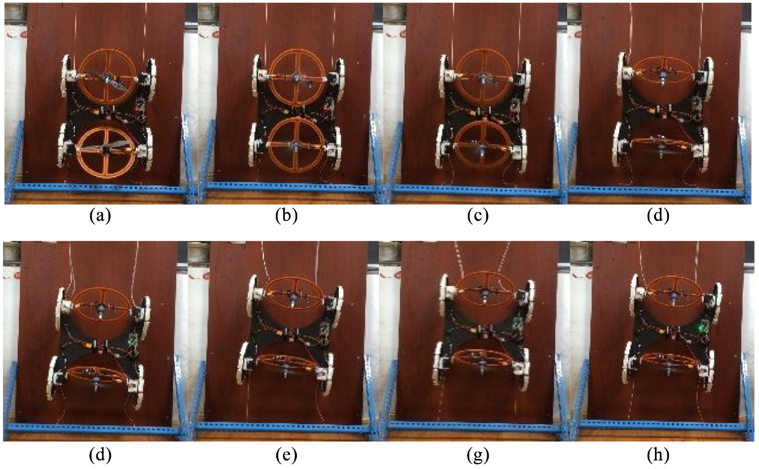
The experimental test of the robot moving on the indoor vertical wall is shown in Figure 17(a) to (l). (a) presents the initial state of the motion start, and the start of the propeller. In (b), the rotation speed of the blades increases, the robot will move, and its body will have a small deviation. In (c), the rotation speed of the blades continues to increase, the robot moves forward, the fuselage is greatly inclined, and the lifting rope appears slack. In (d)–(g), the robot is in the ascent phase, and he realizes a large path change in a short time (the movement time from (c) to (g) is less than 1 s), while its movement distance is 0.24 m and its starting motion speed is greater than 0.24 m/s. (g) the fuselage appears to sideslip. (h)–(l) the robot slowly retreats when the rotor speed is reduced. To better perform the stable adsorption of the wall, it is necessary to adjust the tilt angle of inclination of both the front and rear rotors. Note that, during the wall motion test, the actual propeller robot speed is 60% of the maximum velocity, while the robot was able to stably adsorb on the vertical wall.

The robot motion on an indoor vertical wall (a) initial state; (b) the tilt angle of the rotor is adjusted, and the rotation speed of the paddle is increased; (c) the robot starts to move, and the upper soft rope appears slack; (d)–(g) the robot moves upward along the vertical wall; (g) the robot moves to the top of the limited area, while the lower soft rope reaches its maximum length; (h)–(l) the robot slowly descends after reducing the rotor speed.
The test results show that the robot is able to achieve indoor vertical wall adsorption and movement. Consequently, this lays a good foundation for the motion on the wall without hoisting. However, the body slips when the robot moves. Therefore, its motion stability needs to be further optimized.
Robot performance optimization testing on a vertical wall
In the previous experiment, the robot body tilts to the right in the initial state of motion. This is due to the fact that the robot has insufficient adsorption force to the wall. By adjusting the tilt angle of the rotor, the robot tilt problem in the initial stage can be partially solved. In the experiment, the inclination angle of the front rotor is 55°, while the inclination angle of the rear rotor is 60°. The test experiment for the adsorption optimization of the robot on the indoor vertical wall surface is shown in Figure 18, where (a) is the robot initial state, (b)–(c) present the front and rear rotor adjustment, (d)–(f) show the robot moving upwards along the vertical wall, and (g)–(h) show the robot slowly moving downwards along the vertical wall.

Indoor vertical wall optimization test (a) initial state; (b–d) the tilt angles of the front rotor and the rear rotor are adjusted to 55° and 60°, respectively; (d)–(f) the robot moves upward along the vertical wall; (f)–(h) the speed of the propeller slowly decreases, and the robot slowly descends along the vertical wall.
It can be seen from this experiment that the robot can stably adsorb on the vertical wall and steadily move forward. By adjusting the inclination angle of the front and rear rotors, the robot motion state along the vertical wall is greatly improved. The left and right front wheels move forward in an approximately horizontal straight line, while the main body hardly slips. A promising robot theoretical basis was established by obtaining its motion state with different front and rear rotor inclination angles, in order to achieve stable attachment and practical operation on the outer wall of the underlying building.
Conclusion
A dual-propeller wall-climbing robot, able to stably hold and move on different walls, has been developed. To extract the robot motion characteristics in different motion states, its statics are analyzed in details in two specific scenarios; when he is in transition from the ground to a small slope, and when he is on the slope. The influence of different adjustment methods for the robot rotor tilt angle, different widths of the rotor fixed plate and different propeller-to-ground distances, on the robot traction force, is analyzed. Experimental results show that the robot can obtain a higher traction when using a single-angle rotor adjustment, a narrow rotor fixed plate width and a height of the fixed rotor block of 55 mm. The high performance of the robot in climbing a small slope, a vertical wooden wall and an indoor vertical wall, has been demonstrated. A stable mobility of the robot on the vertical wall was also experimentally proved.
In future work, the mechanical parts of the robot will be further optimized in order to improve its driving efficiency. In addition, a steering mechanism will be added so that the robot can realize the steering function. Moreover, by adding a front-wheel drive mechanism, the robot could achieve more reliable and stable adsorption and movement on the wall, under the combined action of the front wheel drive and the rotor power. Furthermore, the position and posture of the robot will be measured using sensors, while the suitable movement state will be determined by adjusting its posture. Finally, the experiments will be carried out on different types of walls, paving the way toward an optimal robot adaptability.
Footnotes
Handling Editor: James Baldwin
Declaration of conflicting interests
The author(s) declared no potential conflicts of interest with respect to the research, authorship, and/or publication of this article.
Funding
The author(s) disclosed receipt of the following financial support for the research, authorship, and/or publication of this article: This research was supported by the National Key Research and Development Program of China (2019YFB1309600) and Graduate Technological Innovation Project of Beijing Institute of Technology (2019CX20008).
Supplemental material
Supplemental material for this article is available online.
References
Supplementary Material
Please find the following supplemental material available below.
For Open Access articles published under a Creative Commons License, all supplemental material carries the same license as the article it is associated with.
For non-Open Access articles published, all supplemental material carries a non-exclusive license, and permission requests for re-use of supplemental material or any part of supplemental material shall be sent directly to the copyright owner as specified in the copyright notice associated with the article.