
Abstract
This article demonstrates a reconfigurable soft wall-climbing robot actuated by electromagnet. The robot follows the earthworm movement gait and is capable of translation, deflection, and rotation movement while working on a sloping ferromagnetic wall. Also the electromagnetic actuator provides a significant improvement in expeditiousness compared with existing actuation modes. The speed of the robot can be adjusted by modulating the power frequency. When the period of motion cycle is 30 ms, the speed is about 26.5 mm s−1, and the robot can rotate with a velocity of 14.1° s−1 on the horizontal plane. It can also climb a vertical wall at the speed of 12.6 mm s−1. The robot is composed of two kinds of modules which can be connected by the magnets embedded. It can also be reconfigured in different working conditions, such as crossing an inaccessible gap, and thus has the potential to be used in flaw detection, surface cleaning, and exploration of ferromagnetic structures.
Introduction
Robotics has been widely used in manufacturing. As a result, a wide variety of designs are proposed. Robots like unmanned ground vehicles, 1 biped robots, 2 and their control algorithm have been studied deeply and play an important role in our life. Although traditional stiff robotics can provide high accuracy and repeatability, their high masses and complicated structures mean they can hardly change in the face of different environments and tasks. With flexible structures, soft robots are getting more and more attention because of their unique characteristics, such as strong environmental adaptability 3 and high deformability. 4 Mostly inspired by soft animals like caterpillars, 3,5,6 earthworms, 7,8 octopus, 9,10 and spiders, 11 soft robots can easily perform a variety of complex movements and operate within a range of challenging surroundings, which have led to diverse applications such as medical treatment, exploration in complex space, and battlefield rescue.
In this article, we build a reconfigurable modular soft wall-climbing robot which is actuated by electromagnet. It is expected to have the following functions: (1) it should be able to be divided into different modules and can be reconfigured to diverse structures within varying environments; (2) it is supposed to have omnidirectional exercise ability, which means that it not only can move in one direction but also can deflect while translating and rotating around the self; and (3) it should have the capability to crawl on ferromagnetic walls.
Inspiration from earthworms
Earthworms, which can accomplish all kinds of complex behaviors even with a comparatively simple anatomy, are some of the most successful climbing herbivores in the world. 12 Besides, worm-like robots have been studied for at least 30 years. 5 When earthworms move forward, each segment compresses, then re-extends in turn just like the longitudinal wave propagates. Following the earthworm movement gait, some robots have been designed, such as the soft crawling robot reported by Joey et al. which is capable of locomoting on surfaces by manipulating friction. 13 But most worm-like soft robots cannot crawl on sloping surfaces since they need strong adsorption and friction. We also focus on building a robot which can not only crawl on the horizontal plane but also climb on vertical walls.
Reconfigurable architecture
Reconfigurable modular robots, which can reconfigure and adapt themselves to unexpected conditions, have been attracting lots of concerns in recent years. 14 Since the modules can be separated or connected together according to different situation demands, modular robots have more advantages in adaptability, fault tolerance, scalability, and flexibility than a fixed architecture. 15,16 Zou et al., 3 Nemitz et al., 5 and Kurumaya et al. 17 all make their robots modular to achieve a variety of kinematic configurations and locomotion forms.
Actuated by electromagnet
The driving method has always been a difficult point in soft robot research. Considering the weight of motor drivers, electroactive polymers, 18 shape memory alloys (SMA), 7,11,19 –21 and soft pneumatic actuators 10,22 –25 have been main actuation techniques for soft robots. Among these approaches, electroactive polymer actuators always require a high-voltage source, and SMA-based soft actuators need long delay time to cool SMA springs. Meanwhile, soft pneumatic actuators have limitations to make compact robotic system because of their cumbersome appendages like cylinders and gas pipes. What’s more, the motion velocities of soft robots which use these actuators are always low. The earthworm-like robot using an SMA actuator can achieve a crawling motion with a velocity of 0.22 mm s−1. 19 And the pneumatic robot based on caterpillar locomotion can reach speed of 5.1 mm s−1. 3 The low speed has become one of the bottlenecks, limiting the applications of soft robots.
To make the actuator portable and expeditious, electromagnetic actuation system has been developed. Passive electromagnetic devices are flexible and can be tuned in design or during assembly, which can be used to actuate the robotic system with lower cost and higher reliability. 26 Nemitz et al. present a worm-like robot using voice coils in robot actuation, which provides a significant improvement in self-sufficiency. 5 Since electromagnet can exert a force as soon as it is energized, our robotic system chooses an electromagnet as the actuator to increase its speed.
Movement principle
Basic movement gait
The motion of the robot approximately simulates the squirm of an earthworm. Under normal locomotion of earthworms, each segment narrows and widens in turn and waves of motion pass from the rear segment of the animal toward the head (Figure 1(a)). 12 By simulating the earthworm’s squirm, the locomotion process of a three-module robot (Figure 1(c)) is designed (Figure 1(b)). First, the first module (M1) is contracted. Then, the middle segment (M2) is contracted and M1 is extended at the same time. At last, M2 is extended and results in a complete motion cycle and a forward step for the robot. If the above process is repeated, the robot will forge ahead continuously. At least two modules are required to achieve this earthworm-like motion.

(a) Schematic of the earthworm crawling gait. (b) The basic gait sequence of the three-module soft robot. (c) Schematic of the three-module soft robot. (d) A cutaway sketch of one module, showing the principle of the electromagnetic actuator.
To achieve the expansion and contraction of the module, an electromagnet is chosen as its actuator (Figure 1(d)). When the driving electromagnet (DEM) is energized, the iron sheet, which is fixed in the front of the module, is attached to the front end of the DEM, and meanwhile the flexible material is contracted. After that, the DEM is de-energized. Because of the restoring force of the flexible material, the iron sheet returns to the original position. Besides, an adsorption electromagnet (AEM) is mounted on the bottom of the module to increase the friction and stick the robot to ferromagnetic walls. What’s more, the velocity of the robot can be changed easily by modifying the period of the motion cycle, which is controlled by the power frequency of electromagnets.
Omnidirectional movement gait
While the earthworm-like robot can only move forward and backward, a 3 × 3 array is designed to achieve the plane motion (Figure 2(a)). When the modules in the same column or row move together at the same speed, the robot can make translational motion on the plane (Figure 2(b)). If the velocities of different columns are different, which can be controlled by power frequency, the robot will be deflected during the advancement (Figure 2(c)). The gait of rotation is shown in Figure 2(d), where two lines move in opposite directions at the same speed. All gaits follow the actuation time in Figure 2(e). In Figure 2, the electromagnets numbered 1, 3, and 5 are AEMs and the electromagnets numbered 2 and 4 are DEMs.

(a) Schematic of the omnidirectional soft robot. (b) The advancing gaits in four directions. Numbers on the modules indicate the electromagnets in different gaits. (c) Two gaits of offset motions. Numbers on the modules indicate the electromagnets in different gaits. (d) The rotation gaits. Numbers on the modules indicate the electromagnets in different gaits. The first two gaits can achieve counterclockwise rotation and the last two gaits can achieve clockwise rotation. (f) Sequence diagram for energizing the electromagnets in (b to d). Red portions denote that the electromagnets are energized and blue portions denote that the electromagnets are de-energized.
Experiments
Design and fabrication of modules
Two kinds of modules are designed so that different modules can be combined together to an omnidirectional robot. As shown in Figure 3(a) and (b), the A-type module has one DEM to drive the module forward and one AEM to adsorb the module to the wall. One iron sheet is installed on the one end of the elastomeric segment. And there is a gap between the iron sheet and the DEM, which is the step length. So the iron sheet can be adsorbed to the DEM for one step length when the DEM is energized. And the elastomeric segment, which can give a restoring force when the DEM is de-energized, is contracted at the same time. The iron sheet can return to the original position pushed by the elastomeric segment when the DEM is powered off. Two or more modules can be connected by permanent magnets. The A-type permanent magnet (A-PM) is fixed on the iron sheet meanwhile the B-type permanent magnet (B-PM) is embedded in the body. With correct orientation of the magnetic pole, different modules can attract each other easily. As for B-type module (Figure 3(c)), there are three DEMs to actuate in three directions. A 3 × 3 array robot shown in Figure 2(a) can be formed by six A-type modules and three B-type modules.

(a) A side elevation of A-type module. (b) An exploded view of A-type module. (c) An exploded view of B-type module.
The bodies and elastomeric segments are all 3D-printed using UPX 8400 manufactured by AXSON TECHNOLOGIES with a resolution of 0.3 mm. And the electromagnets are purchased with an iron core in the center of every coil. All of the DEMs and AEMs of A-type modules are cylinders, 20 mm in diameter and 15 mm in height. The AEMs of B-type modules are cylinders, 13 mm in diameter and 30 mm in height. The iron sheet is a ferromagnetic round disk whose diameter is 25 mm and thickness is 0.5 mm, so that it can be attached to the front end of the DEM. In addition, neodymium iron boron magnets, which can provide maximize magnetic force with minimal mass, 27 are used to connect different modules. They are all disks with a diameter of 12 mm and a thickness of 1 mm. The magnetic poles of A-PM and B-PM are opposite. So different modules can automatically connect when they are close to each other.
As a result, the A-type module is a 43.2 × 30 × 35 mm3 with the weight of 77 g, while the B-type module’s size is 43.2 × 50.4 × 35 mm3 with the weight of 127 g.
Control of robotic system
We use a SIMATIC S7-1200 PLC controller from SIEMENS CHINA to control the robotic system. And a DC stabilized voltage supply is used to provide electricity (Figure 4(a)). Since the magnetic force of the electromagnet decreases rapidly with the increase of the gap, the step length is designed to be 0.9 mm and the driving voltage is 12 V so that there is enough power to drive the module and keep it from falling off a vertical wall.
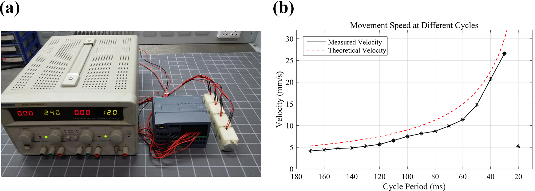
(a) The power supply and PLC controller of robotic system. (b) Movement speed at different cycles.
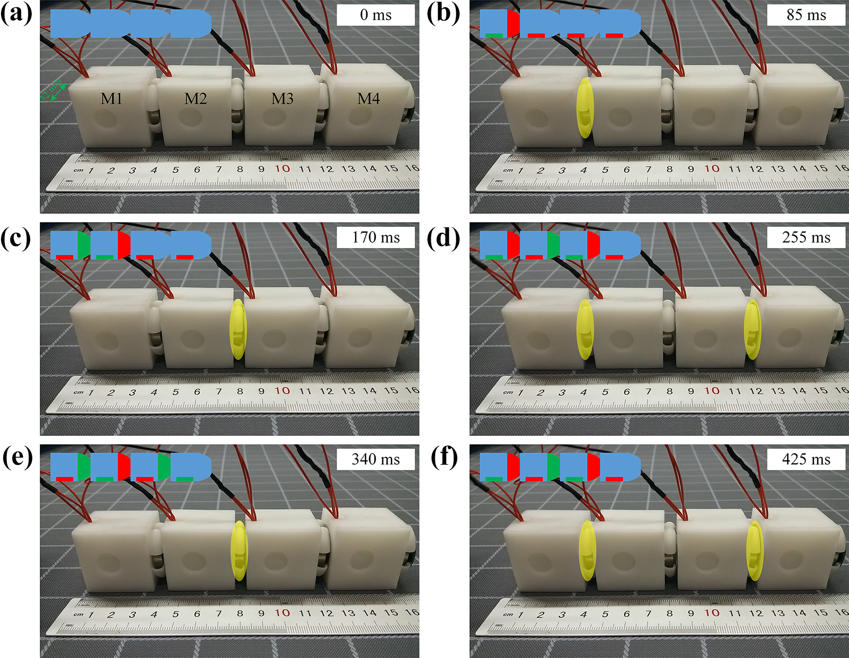
During the moving process of the robotic system, electromagnets are energized and powered off recurrently. So its speed and the cycle time are closely related. A robot containing four A-type modules is fabricated to test the best cycle time of motion. Each module is activated by a square periodic signal, as illustrated in Figure 5. When the typical period of one cycle is 170 ms, gaits of the first cycle are shown in Figure 6. When the robot begins to move forward, AEMs of M2, M3, and M4 are energized to provide the adsorption force. And the DEM of M1 is energized at the same time, driving M1 to move one step length (Figure 6(b)). Then the DEM of M1 and the AEM of M2 are powered off when the AEM of M1 and the DEM of M2 are powered on. So M2 moves forward one step length (Figure 6(c)). After that, the AEM of M2 is energized to adsorb the module on the ground. In the meanwhile, M1 and M3 are actuated to move forward (Figure 6(d)). Afterward, M1 and M3 are motionless and M2 moves one step length driven by its DEM. At the same time, when the AEM of M4 is de-energized, M4 is pushed forward by the elastomeric segment of M3 (Figure 6(e)). Next, M1 and M3 are actuated when M2 and M4 are motionless (Figure 6(f)). The robot will repeat the gaits and keep moving. In this moving process, alternate modules move together so that the robot can reach the maximum speed at this driving frequency. And there are at least half of the modules providing the adsorption force to keep the robot from falling.
Activation sequence of four contiguous modules. (a) The driving signals of driving electromagnets. (b) The driving signals of adsorption electromagnets.

A series of still frames from the video showing a four-module robot crawling forward. Gaits of the first cycle are shown as (a to f). Then the gaits in (e) and (f) will be repeated. Red portions denote that the electromagnets are energized and green portions denote that the electromagnets are de-energized. The elastomeric segments being contracted are highlighted.
The robot moves forward one step length in each cycle. So its speed is determined by the period of one cycle. When T is the cycle period and L is the step length, the theoretical velocity v of the robot is calculated as

The shorter the cycle, the faster the movement. But if the cycle is too short, the module cannot move one step length in such a short period. We test the speed at different cycles to determine the best period of motion when the driving voltage is 12 V (Figure 4(b)). Measured velocities are less than theoretical velocities because of the friction and manufacturing errors of modules. By decreasing the cycle period, the velocity of the robot can be increased to 26.5 mm s−1. But when the cycle period is reduced to 20 ms, the robot vibrates violently and the speed rapidly decreases to 5.2 mm s−1. So the cycle period is finally set to 30 ms to achieve maximum speed.
Results
Unidirectional movement
The four-module robot can move forward based on the gaits shown in Figure 6 with 12 V voltage. When the cycle period is 30 ms, its speed is 26.5 mm s−1 on the horizontal plane (Figure 7(a) and (b)). Because of the DEM at the bottom of each module, the robot can also climb the ferromagnetic wall that is not horizontal. During the moving progress, alternate modules can march simultaneously so that there are at least half of the modules providing adsorption between the robot and the ferromagnetic wall to keep it from falling. In our experiments, the robot can successfully climb on the vertical wall with a velocity of 12.6 mm s−1. What’s more, it can crawl at 14.5 mm s−1 on a 68.5° slope (Figure 7(e) and (f)) and 15.0 mm s−1 under the slope (Figure 7(g) and (h)). The current through the power supply is 1.2 A, which means the typical current provided to each module is about 0.3 A.
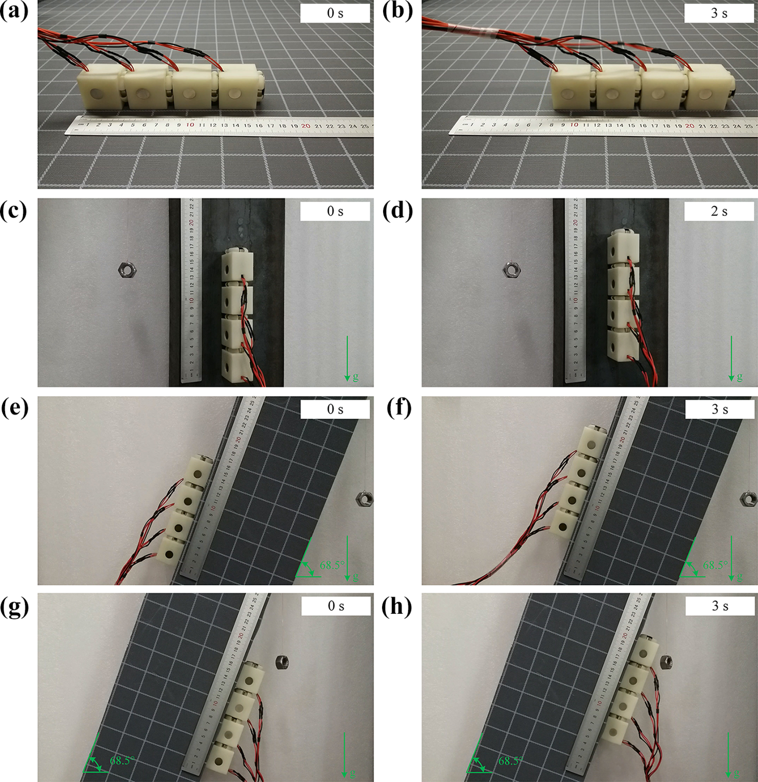
(a and b) The four-module robot crawling forward on the horizontal plane. (c and d) The four-module robot crawling up on the vertical wall. (e and f) The four-module robot crawling forward on a 68.5° slope. (g and h) The four-module robot crawling forward under a 68.5° slope.
Omnidirectional movement
Combined by six A-type modules and three B-type modules, a robot as shown in Figure 2(a) is created. In addition to the translational motions, if the cycle periods of different columns form an arithmetic progression, the different segments will move at different speeds, thus driving the robot to deflect when advancing (Figure 8(a) to (c)). Besides, if the modules on both sides crawl in the contrary directions at the same speed, the robot will rotate with a constant center (Figure 8(d) to (f)). In our test, the rotation speed can reach 14.1° s−1. During the rotation motion, the DEM of the central module can be energized to provide a constant adsorption force so that the robot is able to cling to the wall. The total current of the robot is 2.6 A during the translation or deflection movement, and it is 1.9 A when the robot is rotating.
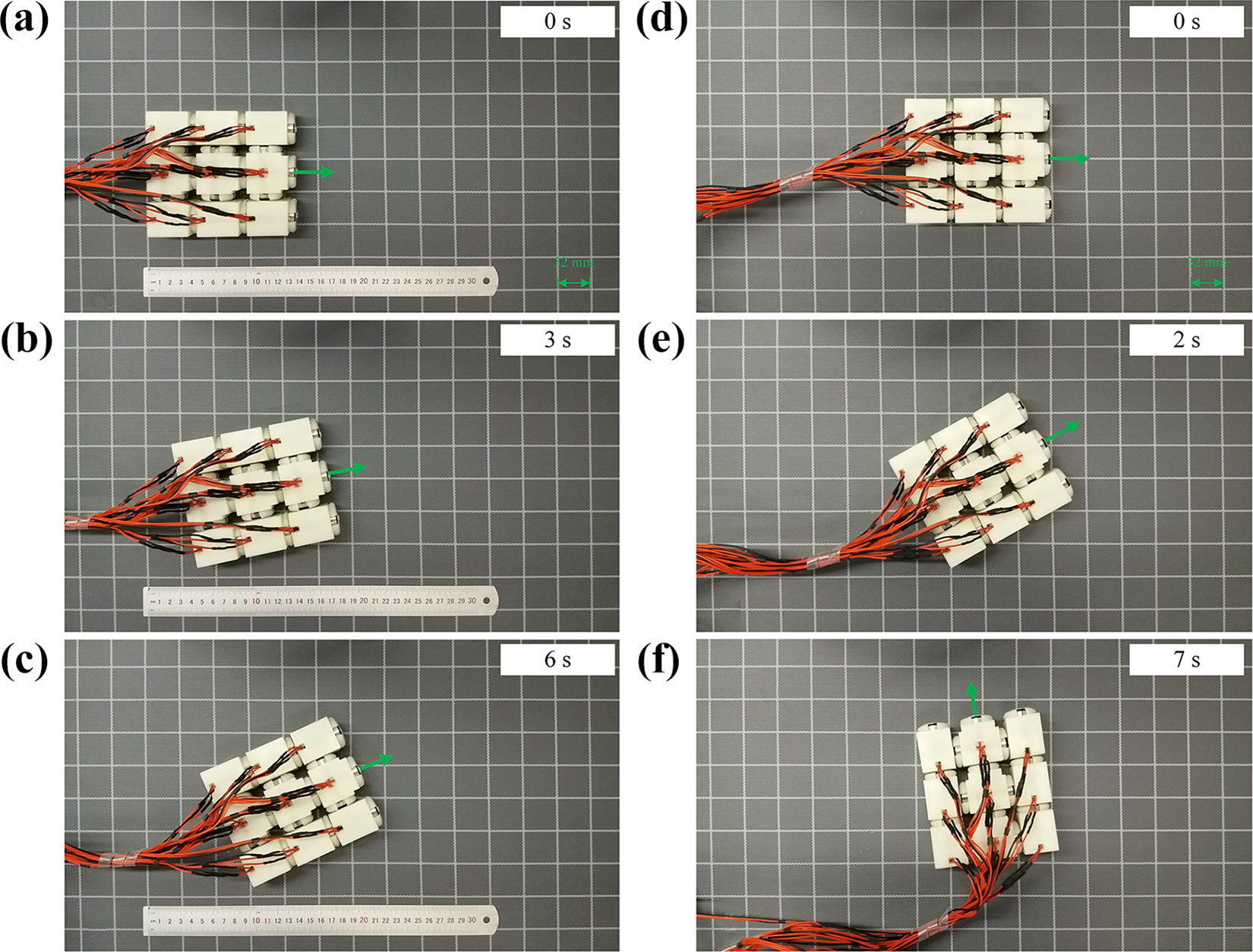
(a to c) Frames from the video showing the omnidirectional robot deflecting to the left while moving forward. (d to f) Frames from the video showing the omnidirectional robot rotating counterclockwise.
Combination of two robots
Since the modules can be connected by the A-PM and B-PM, two omnidirectional robots can dock readily. As shown in Figure 9, a 2 × 3 robot, whose three A-PMs in the front can be attracted by the three B-PMs in the back of the other robot, is combined with a 3 × 3 matrix, which results in a 5 × 3 configuration. And as a reconfigurable modular robot, the modules can also be separated or connected together to adapt to some other different conditions.

Frames from the video showing the docking mission of a 2 × 3 robot and a 3 × 3 robot. The arrows denote the direction of the movement.
Discussion
In our research, we choose electromagnets as the actuators of the robot. Compared with existing actuators used in soft robots, electromagnetic actuators have numerous advantages. Pneumatic actuators have been widely used in soft robots. And a pneumatically powered omnidirectional robot has been designed based on the caterpillar movement gait. 3 While the pneumatic actuator needs a specific pressure gas source, which makes it difficult to control, electromagnets can be controlled by the power supply effortlessly, resulting in a greater accuracy of motion. What’s more, it will be a long way to install the pumps and pipes into the modules, but it’s easier to embed a battery within the cube in future work.
As to a pneumatically actuated robot, the speed mainly depends on the inner pressure of its soft cylinders which have low response rate and low sensitivity. So it’s not easy to control the moving speed flexibly. Differently, the crawling velocity of an electromagnet actuated robot can be changed by modulating the power frequency or cycle period with a fast response, which makes the motions more diverse and expeditious. In our test, the period of a gait cycle is 30 ms, resulting in a translational motion with a velocity of 26.5 mm s−1 and a rotation movement with a velocity of 14.1° s−1.
Many worm-like robots have created specific structures to increase the friction against the floor during the crawling motion, such as elastomeric skin, 5 artificial ribs, 28 and angled nails. 29 Our robot uses the AEM to provide frictional resistance with the surface, which also gives the robot the ability of climbing on a ferromagnetic wall.
The modules can be reconfigured to adapt to different conditions. In this work, the docking of a 2 × 3 array and a 3 × 3 array is completed without precise control. And the robot can be separated and connected again when necessary. To achieve an omnidirectional movement, the robot is required to be a 2 × 2 array at least.
Since each module is an independent unit with its own actuator, it can carry additional load independently. The load capacity of the module depends on the driving force of its electromagnetic actuator. We can increase the driving voltage of the electromagnet or change its structure to achieve a larger load. The driving voltage and cycle period of each module also need to be adjusted to make the robot move forward stably when different modules with unequal loads are connected.
However, the design presented here has some limitations that need improvement. (1) The robotic system is an open-loop system, so it is manually controlled and deviations may occur in long-distance movements. Some sensors should be used to feedback environmental information. (2) It cannot reconfigure automatically. The automatic docking also needs some sensors and automatic control algorithm. (3) It is powered by external power supply, which makes it tethered. And the robot needs high power consumption. When the voltage is 12 V, the current for each module is about 0.3 A, which means the power consumption is 3.6 W for each module. So embedding the battery into the module is still a difficulty constrained by the energy capacity and weight of batteries now.
Conclusion
We designed a reconfigurable soft wall-climbing robot actuated by electromagnet, which provides a new solution to the actuator of soft robot. This robot is capable of translation, deflection, and rotation movement while working on a ferromagnetic wall following the earthworm movement gait. Moreover, it can be reconfigured in different working conditions because of the modular architecture. And modules of the robot can be replaced easily when they are damaged or contaminated instead of discarding the whole robot. The robot has the potential to be used in flaw detection, surface cleaning, and exploration for ferromagnetic structures like steel bridges and steel roof trusses.
Advantages of our modular system are that: (1) it is capable of omnidirectional movement, (2) it can move at high speed, which is 26.5 mm s−1, (3) it can be reconfigured, and (4) it has the ability of climbing on ferromagnetic walls.
Future research will focus on adding some sensors to gather environmental information and achieve the automatic reconfiguration. And electromagnets will be simplified to reduce energy consumption. Then we will try to install power source into the module so that no cables are required.
Footnotes
Declaration of conflicting interests
The author(s) declared no potential conflicts of interest with respect to the research, authorship, and/or publication of this article.
Funding
The author(s) disclosed receipt of the following financial support for the research, authorship, and/or publication of this article: This research is financially supported by the Suzhou-Tsinghua Innovation Leading Action Project (2016SZ0218) and the Tianjin Science and Technology Project (19VFSLQY00090).
Supplemental material
Supplemental material for this article is available online.
References
Supplementary Material
Please find the following supplemental material available below.
For Open Access articles published under a Creative Commons License, all supplemental material carries the same license as the article it is associated with.
For non-Open Access articles published, all supplemental material carries a non-exclusive license, and permission requests for re-use of supplemental material or any part of supplemental material shall be sent directly to the copyright owner as specified in the copyright notice associated with the article.