
Abstract
The harvesting straw feed crops (silage corn, alfalfa, herbaceous mulberry, etc.) was tedious, high-labor-cost, and large-nutrient-loss. A self-propelled straw forage crop harvester, which could realize the integration of cutting, flattening and modulating, chopping, and throwing straw forage crops, was designed. The cutting angle could freely be adjusted between 0° and 8°. The max rotation speed of the flattening roller could reach 590 r/min and could be adjusted consecutively by the hydraulic control device. To verify the performance of this machine, several harvesting experiments of alfalfa, silage corn, and herbaceous mulberry with different moisture, were carried out on this machine. During the experiment, the average working speed of the machine was 1.6 m/s, the cutting height was 40–80 mm, and the flattening rate was 97.14%. It is determined that the suitable cutting speed for harvesting alfalfa is 2131 r/min; the suitable cutting speed for harvesting silage corn is 836 r/min; the suitable cutting speed for harvesting herb mulberry is 1045 r/min. The design of the machine can not only improve labor productivity and reduce the nutrient loss of forage crop but also support the silage harvesting machinery and equipment for forage crop.
Introduction
With the continuous advancement of the “grain-to-feed” policy and the dairy industry policy, our demand for milk, meat, and eggs has been increasing. Straw forage crops were an indispensable source of feed for animal husbandry. How to grow them reasonably on limited land, reduce costs, and increase yield was important for developing the forage grass industry. Silage was a storage technology or method to gain roughage by chopping the green feed with a water content of 65%–75% and then fermenting the crops by anaerobic lactic acid bacteria under the condition of airtight anoxia. After the silage is fermented, it has a sour smell, soft and juicy, good palatability, rich nutrition, good for long-term preservation, and is an excellent source of feed for livestock.1,2 In the 1930s, someone specialized in cutting and flattening harvester. There are many foreign manufacturers producing silage harvester, including John Deere New Holland in the United States, Kuhn in France, and CLAAS in Germany. The silage harvesters produced by these companies are rich in types and gradually develop toward high power, wide range, and high efficiency.3–7 However, these harvesters have a single work and cannot harvest multiple silage crops. They are suitable for large farms and cannot be used for a small field. In recent years, some scholars have done much research on the actual situation of forage planting in China and designed and studied several models for mountainous hills in Ningxia and Gansu Mowing and flattening machines in the area. For example, Zhao and others8–11 have developed a hydraulic walk-behind alfalfa mowing and flattening machine, which is suitable for small-scale land operations. The front mowing and flattening machine studied by Wen12,13 used a reel and a toothed chain type. The front-mounted double-disc mower researched by Zhao et al. 14 and others used a double-disc cutter, which has higher cutting efficiency and better operation effect. Wu and Wang15,16 China Agricultural University, researched alfalfa mowing and flattening harvester, which can adapt to changes in terrain and better perform harvesting operations. These grass cutters are characterized by flexible steering and strong climbing ability, filling the gap of forage harvesting machinery in mountainous areas.
As a measure of increasing production in agricultural production, intercropping plays an important role in China’s grain production. The purpose of intercropping is to plant more than two crops in a limited time and on a limited land area to achieve the effect of increasing crop income and production. However, due to the differences in crop types and planting standards under the intercropping in different regions, such as in China, as well as the imperfect machinery itself, poor adaptability and reliability, the existing domestic models cannot complete the harvesting. In this, the harvesting is mainly based on traditional manual harvesting, which is time-consuming, energy-consuming, low efficiency, and high labor cost as an important reason for restricting developing the model. At the same time, saline-alkali land is an important reserve farming in my country, and making reasonable farming is an important part of its green development. Previous studies have shown that compared with maize monocropping, intercropping of maize and alfalfa can increase soil organic matter content and reduce consumption of various nutrients in the soil.17,18 Therefore, designing a harvesting machine that can harvest corn and alfalfa at the same time has become an important measure to promote developing animal husbandry at this stage.
A self-propelled straw forage harvester was designed to solve the problems of planting mode of alfalfa and silage corn in the salty-alkali area, the single function of forage crop harvester, poor adaptability to the terrain, and large harvest loss. Flattening, modulation, chopping, throwing, and other integrated operations, reducing the subsequent silage process, reducing the loss of nutrition of silage crops, and meeting the requirements of modern livestock.
System design
Overall structure
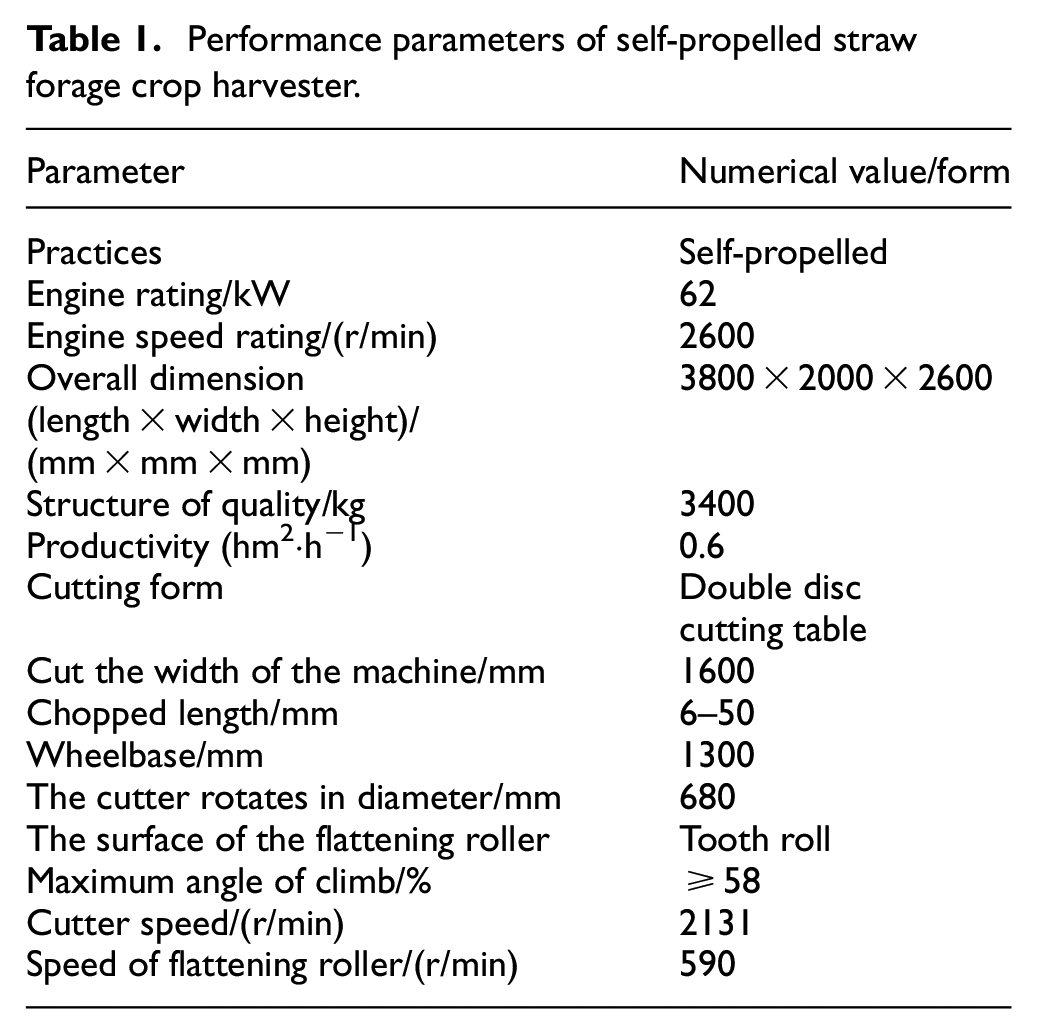
The whole of the self-propelled straw forage crop harvester is shown in Figure 1. It mainly includes a walking device, a cutting device, a flattening and modulating device, a chopping device, a throwing device, etc. The working process was mainly to use the tilting double-disc header to cut the silage crops, the cut crops were transported to the feeding roller through the polymerization of the screw auger, and the feeding roller transports it to the flattening roller, the crops after flattening are thrown to the shredding roller, and the shredded crops are thrown to the storage bin under the action of the feeder for silage use, realizing the cutting-flattening-shredding-toss the whole process. The main parameters of self-propelled straw forage crop harvester are shown in Table 1.

Structure drawing of self-propelled straw forage crop harvester. 1. Cab, 2. Damping spring device, 3. Gearbox, 4. Grain lifter, 5. Double disc cutter, 6. Spiral twisted dragon, 7. Universal coupling, 8. Front feeding roller, 9. Hydraulic cylinder, 10. Rear feeding roller, 11. Reversing gear, 12. Lower flattening roller, 13. Upper flattening roller, 14. Shred roll, 15. Stepless transmission, 16. Throwing blower, 17. Power grading box, 18. Caterpillar, 19. Hydraulic cylinder, 20. Engine, 21. Material storage box, and 22. Flip a mouth.
Performance parameters of self-propelled straw forage crop harvester.
Working principle
The harvester of self-propelled straw forage harvester adopts the crawler power chassis driving of combining self-propelled hydrostatic stepless transmission (HST) and mechanical drive axle in series, which optimized the rules of cutting, flattening, chopping, and throwing. When the harvesting machinery was in normal operation, the machine traveled at a certain speed, and there was a certain relative speed with the stationary plants. The straw lifter pushed the crop plants at this relative speed (the direction is the forward direction of the machine) and gathered them in the middle, which was convenient for double-disc cutters cut crops. The crops cut by the cutter were transported back to the screw auger along the bottom of the cutting table under the driving action of the cutter turntable and the airflow field. The crops were gathered to one end by the screw auger and then pushed to the front feeding roller by the gears on the screw auger, the front and rear feeding rollers of the conveying part, combing and squeezing while conveying. After combed and squeezed, the silage crops were transported to the flattening roller, after being flattened and modulated by the flattening roller, they were chopped by a shredder, and the chopped crops were thrown to the storage bin by a conveying fan. Silage crops can be harvested at one time by mowing and flattening, shortening the harvest time, ensuring timely, enough, and seasonal harvest of silage crops. Finish the harvest at one time to reduce the loss caused by the drying. Besides, after the crop stalk is flattened, the palatability is better, which is more conducive to digestion and absorption of livestock and poultry.
Key component design
Cutting device
To better adapt to the terrain, improve the harvest characteristics of straw forage crops, and lessen the harvest loss of straw forage crops, the machine adopted a double-disc rotary cutter with adjustable harvest height. The cutting device is mainly composed of the cutter, cutter head, hydraulic push rod, gearbox, cone drum, spiral auger, etc, as shown in Figure 2. The cutting device also includes a cutting system, feeding system, and a conveying system. The cutting system mainly adopts combining twist cutter and tilting disc. The torsion cutter can lift the crop while cutting crop stalks, to avoid re-cutting and reduce the re-cutting rate. There are two kinds of cutters installed on the cutter head: one is the triangular cutter, which is used to cut alfalfa, etc. The other is a twisted rectangular flapping knife, which is used to cut silage corn and other crops. The tilting disc could reduce the working height of the cutter, thus reducing the stubble. The feeding and conveying system consists of a straw guiding roller on the cutter head and a spiral auger behind the cutter. The straw guiding roller adopts a conical cylinder structure, which is attached with a protruding grass guide plate, which can transport the crop backward in the process of crop harvest. Four guide blades are welded on the screw cutter to accelerate the crop moving along the radial direction of the spiral blade to the side of the cutter. The structure can effectively prevent silage from blocking in the middle of the drum. The hydraulic push rod is arranged at the lower part of the cutter, which can support the cutting device and adjust the rake angle of the cutter freely between 0° and 8°. When the hydraulic push rod is used to cut the crops, the hydraulic push rod is used to adjust the rake angle of the cutter, to realize the crop close to the ground. The cutter head is installed with a cone roller, and the cone roller is equipped with a grass guiding device to mow the fallen crops.
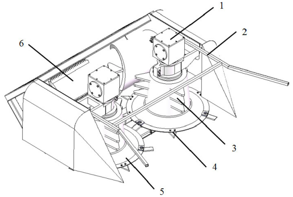
Schematic diagram of the cutting device structure. 1. Gearbox, 2. Tiller, 3. Conical drum, 4. Cutter, 5. Cutter plate, and 6. Spiral twisted dragon.
A double-disc cutter is adopted. The blade length is 120 mm, the extension length is 70 mm, and the top diameter of the cutter is 680 mm. The angle of the header can be adjusted freely from 0° to 8°. In the working of the double-disc cutter, the motion of the cutter is a combined motion of sending motion and rotation motion. The area swept by the cutting edge line to the ground is the cosine band (Figure 3), and its bandwidth is similar to the height of the cutting edge. 19 The motion equation of point a, b of the blade is as follows:


where, xa, ya were the corresponding value of an in the x and y coordinates of the cutter (m); xb, yb were the corresponding value of b in the x and y coordinates of the cutter (m); r is the internal end radius of the cutter (m); R is outer end radius of cutter (m); w is the rotational angular speed of the knife (rad/s); t is the turning time of the knife (s); γ is the Angle between the inner and outer ends of the cutter and the center of the plate (rad); vt is the forward speed of the machine (m/s).
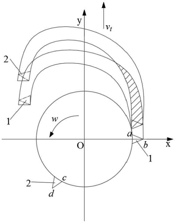
Trajectory of the rotary cutter.
From the test, a minimum speed for cutting the blade root point limits to 30 m/s, to ensure that the cutter work performance is good, and cutting speed vg should be greater than the minimum speed limit, generally take 50–90 m/s, 19 but the greater the speed, heavy cutting, the greater the chances of grass and cutter and guide device speed is consistent, so also the transmission of grasscutter speed, as shown in Figure 4. The speed va at any instant is:

When

Velocity analysis of the internal endpoints of a cutter.
The calculation formula of cutting speed is obtained:

where, n is the knife dish speed (rad/s); vd is the cutting speed of a cutter, vd = 70 m/s; vt is the forward speed of the machine, vt = 5 km/h; r is the internal end radius of the cutter, r = 0.32 m.
The number of cutters in the cutter is determined by the sum of the cutter advance H (the forward distance of the machine when the disc rotates one circle) and the longitudinal width of the remaining swing belt of each blade in one advance is equal to H. The calculation formula for the number of cutters on each cutter plate is:
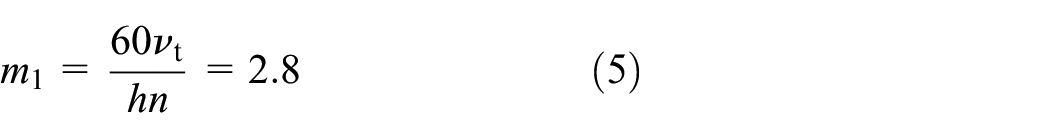
where, vt is the forward speed of the machine, vt = 5 km/h; h is the length of cutting edge line, 0.05 m; n is cutter speed, n = 2131 r/min.
Therefore, the number of cutting knives on each knife plate is three pieces.
Design of conveying flattening device
After cutting the silage crops through the screw auger, it enters the front and rear conveying rollers. The combination of sawtooth and round rollers is selected. The sawtooth conveying roller can increase the grasping ability of the crops so that the crops can be fed smoothly. In the process of entering and working at the same time, it has a certain compaction and combing effect on the crop, as shown in Figure 5.

Conveying flattening device. 1. Upper flattening roller, 2. Rear conveying roller, 3. Front conveying roller, 4. Lower flattening roller, and 5. Adjust the clearance.
The flattening roller has the functions of flattening modulation and feeding. The crop is fed to the chopper roll for cutting. The feeding function of the flattening roller depends on the friction thrust of the rotating flattening roller on the crop, as shown in Figure 6.

Force analysis of feeding roller.
There are two types of forces applied to the crops during the feeding operation: one is the pressure N acting on the midpoint of the contact arc of the crop layer; The second is the friction force f·N, where f is the friction coefficient of the roller on the crop, σ is the angle of friction and the friction force f·N is perpendicular to the positive pressure. The resultant force of pressure N of the two rollers is 2 Nsinα, α is the angle between the rotary center of the upper and lower rollers, and the positive pressure and the direction are horizontal outward, which has an inhibitory effect on the feeding of crops. The frictional force 2 f·Ncosσ is horizontal inward as the feeder. To feed crops successfully, the following requirements should be met:

Namely

Therefore, as long as this condition is satisfied σ ≥ α, the crop can be smoothly fed into the cutting roller.
The flattening effect on crops is accomplished by modulating the power box, universal joint, upper and lower flattening rolls, and gap adjusting device. The modulation power box includes a power output shaft with driving gear, driving shaft, and driving shaft. The main components of the automatic adjusting device are bearing with sliding block and adjusting spring.
The flattening power distribution box provides power for the upper and lower rollers respectively through the universal joint. The rotating speed is the same, but the rotation direction is opposite, to achieve flattening and feeding purposes, as shown in Figure 7.
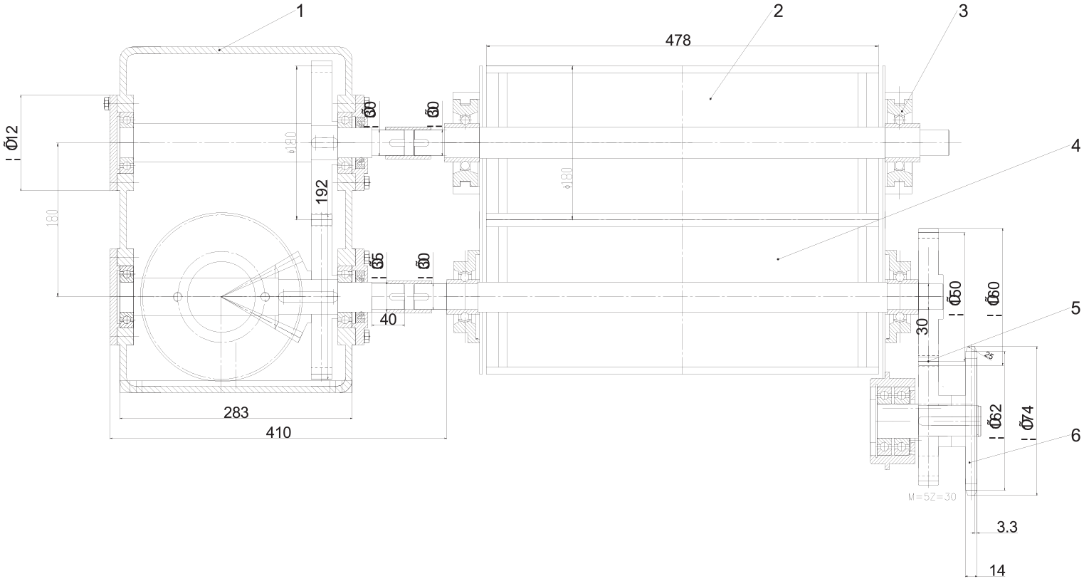
Flattening roller drive. 1. Modulating power box, 2. Upper pressing flat steel roll, 3. Automatic regulating device, 4. Lower pressing flat steel roll, 5. Gear, and 6. Sprocket.
On the premise of flattening under normal feeding conditions, the phenomenon of roller jamming when the feeding quantity increased suddenly is prevented. Therefore, an automatic adjusting device is needed to realize the up and down movement of the flattening roller. The bearing with sliding block seat and the adjusting spring is used to adjust each other. When the feeding amount is large and the pressure reaches a certain degree, the upper roller can move upward automatically, to avoid blocking the roller. When the machine is running, the power transmitted by the engine to the hydraulic pump through the belt is transmitted to the modulation power box. The bevel gear of the lower shaft in the box turns 90° and the lower shaft transmits power to the upper shaft through the gear. The transmission ratio is 1:1. The upper and lower shafts of the box drive the upper and lower rollers to rotate and flatten through the universal joint. The rotation speed of the two rollers is the same, and the rotation direction is opposite, to realize the flattening operation of the two flattening rollers.
The linear speed of the flattening roller is about 3.5–4 times the forward speed of the machine, 20 and the diameter of the flattening roller is 180 mm, so the speed of the flattening roller is:

The speed of the flattening roller can be stepless regulated by the hydraulic speed regulating device.
Design of cutting device
The cutting capacity of the chopping device determines the productivity of the machine. This machine adopts the hob type chopper. Combined with the previous experimental analysis and literature review, it can be seen that for the comminution of crops, when the rotating speed of the shaft is the same, using the straight blade knife under the same working conditions, the energy consumption for processing the same quality of the grass is less and the chopping effect is better. Therefore, the straight blade is selected as the chopping blade. In the process of chopping, it can be divided into tangent and sliding cutting.
Tangent-A cutting method in which the absolute direction of the cutter is perpendicular to the cutting edge. The tangent is divided into three cutting methods: horizontal cutting, oblique cutting, and cutting according to the difference of the straw material, as shown in Figure 8.

Diagram of cutting mode: (a) tangent, (b) crosscutting, (c) oblique, and (d) cutting.
The experiment shows that: due to the different fiber structure of crops, the angle between the direction of the cutter entering the stem and the direction of the structure of the stalk is different due to the different fiber structure of the crop, so the resistance and power consumption will be different when cutting. The cross-cutting resistance is the largest, and the power consumption is also the largest. The resistance of oblique cutting is 30%–40% less than that of cross-cutting and the resistance of cutting is 60% less than that of cross-cutting.
Sliding cutting – A cutting method in which the absolute motion speed of the cutter is not vertical or parallel to the cutting edge. As shown in Figure 9.

Schematic diagram of sliding angle.
where, Vn is the normal velocity of the knife motion (m/s); Vt is the tangential velocity of the knife motion (m/s); α is the angle between the absolute velocity direction and the normal velocity direction of knife motion is the angle of slide cutting.
The mechanical test results show that when cutting the same material and the same depth, the larger the tangential slip, the smaller the force used. This is the famous Goliath constant theorem. 21 The reasonable sliding angle can reduce power consumption and cutting force, and the reasonable range of sliding cutting angle is 5°–20°. 22 If the structure allows, a larger sliding angle can reduce cutting power consumption. The designed sliding cutting angle of the machine is 15°, that is, the included angle between the cutting edge lines of the moving knife and the main axis of the cutting drum is =15°, the cutting front angle is 50° and there are 18 movable blades arranged in two rows in herringbone shape. The width of the knife roller is 380 mm, the diameter of the knife roller is 290 mm, and the rotation speed of the drum is 1400 r/min. The position of moving blade line AB in space is shown in Figure 10.

Spatial position of moving blade line.
As shown in the figure, the rotation axis of a certain blade line AB of the moving knife is OZ, and the rotation trajectory equation of AB is the hyperboloid of a single blade in space. Taking O point as the center, the equation of a hyperboloid of a single blade is:

where, a is the solid half axis of a hyperboloid of one leaf; c is the imaginary half axis of a hyperboloid of one leaf.
The equation of two lines cans be obtained by taking x = a plane:

The second equation is the equation of the blade line AB. It can be seen from the figure that the rotation radii of the endpoints A and B of the blade line are RA and RB. The blade line AB = b and the angle CDB = α.
As shown in the projection of AB on plane XOZ, AC = b2, CB = b1 in the direction of OY, then from the Pythagorean theorem of right triangles, it can be obtained:


Set △BCD area to S, then:

And because

Substitute the above data into equation (9):

Or:

Equations (15) and (16) are the general equations of the hyperboloid of a single blade for the blade line rotation track of a flat drum cutter.
The design of the throwing device
The function of the throwing device is to throw the crops cut by the chopping device into the storage bin. Due to the small density of the crops, only the chopping roller is used to chop the crops before throwing them. The height of the crops thrown out is limited and cannot reach the storage bin. Therefore, the throwing blade device must be added. The working process of the throwing stage is divided into three parts: the first is the high-speed rotating impeller throwing the crops. In this process, the centrifugal force of the crops is greater than the centrifugal force of the airflow, and the material gains the upward throwing force; the second stage is the crops throw up along the straight pipe, at this time the crop will receive the friction of the straight pipe part, at the same time, due to the rotation of the fan, an airflow field will also be generated, the crop will be thrown upward under the action of the airflow field; in the third stage, the crop will be partly thrown through the arc tube to the storage bin, the crop collides with the arc tube wall during this process.23–27 The diameter and width of the designed throwing device are 200, 420 mm, and the number of blades is 4. The installation of the throwing device is shown in Figure 11.

Installation diagram of the thrower. 1. Flip a mouth, 2. Throwing blower, 3. Shred roll, 4. Lower flattening roller, 5. Upper flattening roller, and 6. Clearance regulating device.
The peripheral linear velocity of the feed shredder’s blade is 30–43 m/s, 19 which can complete the throwing process. The rotation speed of the throwing device can be expressed as:

where, Np is feeder speed, r/min; Vp is blade linear velocity, m/s, Vp = 43 m/s; Dp is leaf blade diameter, m, Dp = 0.4 m.
Therefore, the calculation can obtain:
Np = 2054 r/min.
Prototype test
Test preparation
The alfalfa harvest test was completed in Beisu Town, Wuji County, Shijiazhuang, and the Quality Supervision and Inspection Center of Machinery Industry Livestock Machinery Products. Alfalfa was selected as they forage in the experiment. The test was conducted from April 10 to April 14, 2019, and the harvest test was conducted for five consecutive days, as shown in Figure 12(a). Alfalfa was in the budding stage with the moisture ranged from 70.04% to 88.23%. The plot with flat terrain, good growth of alfalfa, even growth of alfalfa, and no obvious lodging phenomenon was selected. At the same time, the harvesting experiments of silage corn and herbaceous mulberry were carried out. The average height of alfalfa was 80 cm. Before the test, check the operation site to ensure that there is no debris such as large stones. The test instruments and materials prepared for the field performance test are 100 cm leather tape measure, benchmark pole, sickle, scissors, sealed bag (for weighing broken grass), electronic scale (0.01 g), and marker. According to the relevant industry or national standards of green feed harvesting machinery, the cutting, flattening, chopping, and throwing tests of the whole machine were carried out.28,29

Field test: (a) alfalfa harvest test, (b) mulberry harvest test, (c) silage corn harvest test, (d) measuring the stubble height, and (e) length of alfalfa chopped and flattening.
The silage corn harvest test was completed in Wuji County, Shijiazhuang, Hebei Province, as shown in Figure 12(b), from August 20 to August 24, 2019, for 4 consecutive days. Silage corn was in the late stage of milk ripening. The flat terrain, good growth, uniform growth, no obvious lodging phenomenon, was selected to test. The average height of silage corn was 280 cm with the moisture ranged from 76.38% to 89.34%. Check the operation site to ensure that there are no big stones and other debris obstacles.
The herbaceous mulberry harvest test was completed in Xingtai County, Hebei Province, as shown in Figure 12(c), from August 28 to August 29, 2019, for 2 consecutive days. The herbaceous mulberry is in the harvest period with the moisture ranged from 66.7% to 79.1%. The flat terrain, good growth, uniform growth, no obvious lodging phenomenon, was selected to test. The average height of herbaceous mulberry was 120 cm. Check the operation site to ensure that there are no big stones and other debris obstacles.
Experimental method
To determine the influence of the machine squeezing roller speed on the alfalfa squeezing rate, by adjusting the speed of the flattening roll through the hydraulic speed regulating device, three different speed ratios of the flattening roll are realized, which are low, medium, and high. The calculated speed ratios are 3.21, 3.61, and 4.13, respectively. Taking into account that the machine’s forward working speed will affect the cutting height, low-speed (1.4 m/s) and high-speed (1.6 m/s) alfalfa harvesting experiments were carried out at three-speed ratios. To test the optimal cutting speed of the machine for harvesting alfalfa, silage corn, and fodder mulberry, referring to previous studies on the speed of harvesting silage crops, three kinds of silage crops were harvested at three different cutting speeds. That is, when harvesting alfalfa, the cutting speeds are 1941, 2131, and 2239 r/min; when harvesting silage corn, the cutting speeds were 687, 836, and 985 r/min; when harvesting herb mulberry, the cutting speeds were 896, 1045, and 1194 r/min, totaling nine group tests, using the stubble flatness as the evaluation index to determine the cutter speed. Five sampling points were randomly selected on the selected plots, each of which was 1 m × 1 m. The test indicators were average stubble height, out-of-tolerance loss rate, grass fragmentation rate, flattening rate, etc.
Experimental results and analysis
The machine carries out a series of operations under normal working conditions. Five sampling points are randomly selected on the selected plot, each sampling point is 1 m × 1 m. The test indexes are average stubble height, out of tolerance loss rate, grass crushing rate, flattening rate, etc.
Average stubble height
The height of the stubble in the test area was measured. During the measurement, the stubble height was measured along the working direction of the machine in the whole cutting width. Twenty stubble height was measured at the same distance each time and the average value was taken, as shown in Figure 12(d).
The high-stubble loss rate
The percentage of the loss mass caused by the average per unit area cutting stubble exceeding the technical requirement and the weight of the herbage to be harvested per unit area was determined as the high-stubble loss rate. According to equation (18):

where, Sz is out of tolerance loss rate, %; gy is quality of herbage per unit area, g/m2; gs is actual forage quality per unit area, g/m2.
Sloppy
The ratio between the mass of grass cuttings (<7 cm) formed in the process of recutting and flattening in a unit area and the mass of grass harvested in a unit area is the loss rate of grass cuttings. According to equation (19):

where, Ssy is broken hasty, %; gsy is grass mass per unit area, g/m2; gy is quality of herbage per unit area, g/m2.
Flattening rate
Among the harvested herbage per unit area, the ratio of the mass of the compressed herbage to the mass of the harvested herbage per unit area is the flattening rate, as shown in Figure 12(e), which is calculated according to equation (20):

where, Yb is flattening rate, %; gw is quality of uncompressed herbage per unit area, g/m2; gs is actual forage quality per unit area, g/m2.
The machine field test results are shown in Tables 2 and 3.
High-speed field operation speed (1.6 m/s) test results.

Low-speed field operation speed (1.4 m/s) test results.

To compare the results of repeated experiments under different speed ratios, a single-factor analysis of variance was used to sort and analyze the data. The sorted data results are shown in Tables 4 and 5.
Analysis of variance of compressibility of different speed ratios in a high-speed field operation (1.6 m/s).

SS: sum of square; df: degrees of freedom; MS: mean square; F: test statistics; p-Value: the observed significance level; F crit: critical value.
Variance analysis of compressibility of different speed ratios in low-speed field operations (1.4 m/s).

SS: sum of square; df: degrees of freedom; MS: mean square; F: test statistics; p-Value: the observed significance level; F crit: critical value.
The harvest test results of three silage crops with different cutting head speeds are shown in Table 6, and the stubble flatness is shown in (Figure 13).
Stubble quality of three silage crops at different speed of the cutting table.


Stubble smoothness of alfalfa under different cutting speeds: (a) 1941 r/min, (b) 2131 r/min, and (c) 2239 r/min.
Analyzing the data in the table can be drawn, when the machine is operating at high speed in the field, and the cutter flattening roller speed ratio is 3.21, 3.61, and 4.13, respectively, F > F crit and p-value <0.01, the flattening rate of alfalfa showed a significant difference, and the specific manifestation was that with the continuous increase of the speed ratio of the cutter flattening roller, the flattening rate of alfalfa showed a downward trend. When the machine was operating at low speed in the field, the alfalfa flattening rate also showed a significant difference, but when the speed ratio was 4.13, the alfalfa flattening rate showed a small trend, at this time the flattening rate was 93.57%. In the case of the same speed ratio, the cutting height of the machine during high-speed operation is higher than that during low-speed operation, and the over-tolerance loss rate increases accordingly. Analyzing the results of three different cutting blade speed harvesting experiments on three silage crops, it can be concluded that the cutting blade speed affects the flatness of the cutting stubble. The suitable cutting speed for harvesting alfalfa is 2131 r/min; the suitable cutting speed for harvesting silage corn is 836 r/min; the suitable cutting speed for harvesting herb mulberry is 1045 r/min
Through the test results, the test prototype can smoothly cut, flatten, chop, and throw silage crops. The cutting height is neat, the flattening effect is obvious, and good shredding effect, the height of the cutting stubble is 40–80 mm, the out-of-tolerance loss rate is 0.36%, the grass fragmentation rate is 2.46%, and the flattening rate is 97.14%. The prototype can smoothly complete a series of cutting, flattening, shredding, and throwing processes, and the operating results have reached national standards. Since the machine can complete the alfalfa harvesting operation completely, the subsequent picking and bundling process of the alfalfa cutting and flattening process is reduced, so the loss rate of shredded grass after the traditional machine operation is avoided, resulting in the loss of alfalfa harvesting yield. The prototype can well complete the alfalfa harvesting work.
Conclusion
In this article, a self-propelled silage harvester was designed. The cutting device, flattening device, chopping conveying device, and throwing device is mainly designed.
The machine adopts a double-disc header. The designed cutting table speed is 2131 r/min, and the machine’s forward speed is 1.6 m/s when it is working. At this time, the cutting work goes on smoothly, and the flattening roller speed is 590 r/min. The speed of the squeezing roller can be adjusted seamlessly through the hydraulic speed regulating device. The gap of the squeezing roller can be changed with the change of the feed amount. The speed of the shredding roller is 1400 r/min, and the shredding length is 6–50 mm, the throwing speed is 2054 r/min, it can be thrown to the storage bin smoothly, and the prototype can better complete the cutting, flattening, modulation, shredding, and throwing processes.
Field tests were conducted on the experimental prototype. The average stubble height of the prototype was 61.6 mm, the high-stubble loss rate was 0.36%, the shredding rate was 2.46%, and the flattening rate was 97.14%. The operation effect reached the relevant national standards. The stubble height of the prototype needs to be for further optimization.
The harvest test of three kinds of silage crops with different moisture by different header speeds on the test prototype, that is, the header speed when harvesting alfalfa is 2131 r/min; the header speed when harvesting silage corn is 836 r/min; when harvesting herb mulberry, the cutting head speed is 1045 r/min.
This research provides a theoretical basis for the design and manufacture of silage machines and a new idea and method for harvesting silage crops.
Footnotes
Handling editor: James Baldwin
Declaration of conflicting interests
The author(s) declared no potential conflicts of interest with respect to the research, authorship, and/or publication of this article.
Funding
The author(s) disclosed receipt of the following financial support for the research, authorship, and/or publication of this article: The authors acknowledged the financial support from the Chinese National Key Research & Development Plan (NO.2016YFD0701701-01).