
Abstract
The manufacturing industries still face the most challenging job at hand to machine nickel-based superalloy, Inconel 718, efficiently and economically. In contrast to the extensive research efforts in secondary machining processes such as turning, milling and drilling, very little or no attention is paid on bandsawing of Inconel 718. This article presents an experimental investigation of machining Inconel 718 using carbide-tipped bandsaw teeth in a custom-made experimental facility. Cutting forces were measured during the bandsawing operation using a dynamometer, and the wear modes and mechanisms in the bandsaw teeth were investigated in a scanning electron microscope. Three different feeds or depths of cut (10, 20 and 30 μm) were employed with a cutting speed of 30 m/min during the machining tests. At smaller feed or depth of cut (10 μm), abrasive wear, adhesive wear and some degree of plastic deformation were identified as the governing mechanisms of tool wear. The higher depth of cut (30 μm) could cause cracking, chipping or premature failure of the carbide tip in bandsaw tooth. Strong welding of workpiece material to the cutting edge formed a built-up edge, which would impair the bandsawability due to the modification of the cutting edge. The higher depth of cut significantly improved the machining performance due to the reduction in specific cutting energy. However, it was not recommended to apply higher depth of cut as there were obvious possibilities of premature tooth failure. Machining force and specific cutting energy results along with chip characteristics were correlated with the tool performance and tool wear. The results of this investigation would be helpful for bandsaw manufacturers and end users to get a fundamental understanding of the bandsawability of Inconel 718 with the carbide-tipped bandsaw.
Keywords
Introduction
Material engineers are continuously facing the challenges to develop high-strength materials for demanding applications such as in aerospace industry. At the same time, the cutting tool industries are facing the challenges to machine the materials at an economic rate with high dimensional accuracy and better cut-surface quality. One such material is nickel-based superalloy Inconel 718, which is commonly employed in the aerospace, nuclear and biomedical industries, owing to its superior mechanical, thermal and chemical properties such as high yield strength, high fatigue strength, good creep and oxidation resistance at elevated temperatures. The aforementioned attractive properties of Inconel 718 alloy are also responsible for its poor machinability, making it one of the most well-known ‘difficult-to-machine’ materials.1–7 The ability of Inconel 718 to retain its strength at elevated temperatures, leads to high cutting forces, which are roughly twice when cutting medium carbon steels. Inconel 718 has low thermal conductivity (11.4 W/mK) which leads to the generation of high temperature at the tool–workpiece interface. Inconel 718 has high affinity to react with almost all tool materials, leading to attrition and diffusion wear of the tool. Moreover, Inconel 718 is sensitive to high strain rate and hence rapidly work hardens causing abrasive wear of the tool.8,9 The presence of hard phases in the micro-structure, such as carbide and oxides, further accelerates abrasive wear of the tool. In addition, the chips are easily welded onto the tool, leading to the formation of built-up edge (BUE). 10 Workpiece geometry can also have great influence on tool wear and machining efficiency when milling of Inconel 718 curved surface parts. 11 It has been shown that change in cutting force due to variation of geometric features affects both tool wear and machined surface quality. All these factors adversely affect the tool life for machining Inconel 718. Inconel 718 is stated to be 16, 6 and 4 times more difficult to machine than aluminium, mild steel and stainless steel, respectively. 12 Higher cutting forces in machining Inconel 718 demand tool materials which have high wear resistance and toughness in order to avoid rapid tool deterioration or premature failure.
In order to achieve an economic tool life, it is vital to select right tool material, favourable tool geometry and optimum machining parameters (i.e. feed, speed and depth of cut). Machining of Inconel 718 in an efficient and economical way is always a challenge for the cutting tool industry owing to the short tool life. Tool materials for machining Inconel 718 include cemented carbides, ceramics, polycrystalline diamonds and cubic boron nitride (CBN). Cemented carbide tools are preferred, as they possess higher toughness compared to the other tool materials and are also economical to manufacture. Therefore, evaluation of machining performance of various carbide tools was subject to many scientific studies.5,10,13 A detailed overview of the tool wear characteristic for different tool materials used to machine nickel-based alloys is given by Zhu et al. 14 and Akhtar et al. 15 Flank wear, crater wear, chipping or fracturing and notching at the tool edge are found to be the dominating wear and failure modes when machining Inconel with the carbide tools due to a combination of high thermal and mechanical stresses. In general, abrasion, adhesion, BUE formation, diffusion and cracking were observed, which are the common wear mechanisms in carbide tools during widely used Inconel machining processes such as turning,1,5,16–18 milling3,10,13,19–21 and drilling.22–24
In contrast to other sawing techniques, bandsawing is widely used in cutting-off operations and offers competitive advantages of higher metal removal rate, lower kerf loss, better straightness of cut, competitive surface finish and a longer tool life. A number of scientific studies have been reported in the literature to provide an insight about bandsaw tooth design, mechanics of bandsawing, bandsaw performance and wear modes and mechanisms in bandsaw cutting edges.25–28 Majority of these studies were focused on the bandsawing of steel workpieces with bi-metal high-speed steel (HSS) bandsaws. 29 However, very limited literature is available in public domain related to machining with carbide-tipped bandsaws.30,31
Bandsaw blades for metal cutting are mainly of two kinds, bi-metal blades with the cutting edges made of HSS and carbide bandsaws with tungsten carbide teeth. While carbide-tipped bandsaws have been developed for cutting difficult-to-cut materials, bi-metals are still the most widely used bandsaws for cutting-off operations. The initial cost of a carbide bandsaws is approximately twice that of the bi-metal bandsaws, but the cost per cut for carbide blades in most of the cases is much less than that for the bi-metal bandsaws. 32
Carbide-tipped bandsaws are very popular in cutting nickel-based superalloys such as Inconel 718. The main benefits of the carbide bandsaws over the bi-metal bandsaws are long blade life owing to harder and more heat resistant carbide tips, higher productivity owing to higher feed rate, lower cost per cut owing to higher sawing rate and lower downtime for blade changing. The sawing rate could be three times higher with carbide-tipped bandsaw compared to bi-metal bandsaw when machining Inconel.32,33
With the requirements of new materials to meet demands of new and innovative products, the manufacturing engineers and hence the bandsaw users and suppliers have the tasks of cutting these new materials efficiently and economically. Some progress has been made in the development of carbide bandsaws such as introducing improved carbide tip material, quality of tip surface and edge characteristics and tooth design. 33 However, it is important to gain an understanding of the fundamental nature of the cutting process, wear and failure modes and how they are influenced by depth of cut, tool material, workpiece materials and tool design associated with carbide-tipped bandsawing. Although considerable efforts have been invested by the scientific community on the secondary machining (e.g. turning, milling and drilling) of Inconel 718, very little or no attention is paid on machining of the same by the primary machining processes such as bandsawing. The aim of this investigation is to study the machining characteristics of Inconel 718 with carbide-tipped bandsaw teeth under interrupted orthogonal turning condition.
Experimental procedure
Workpiece material
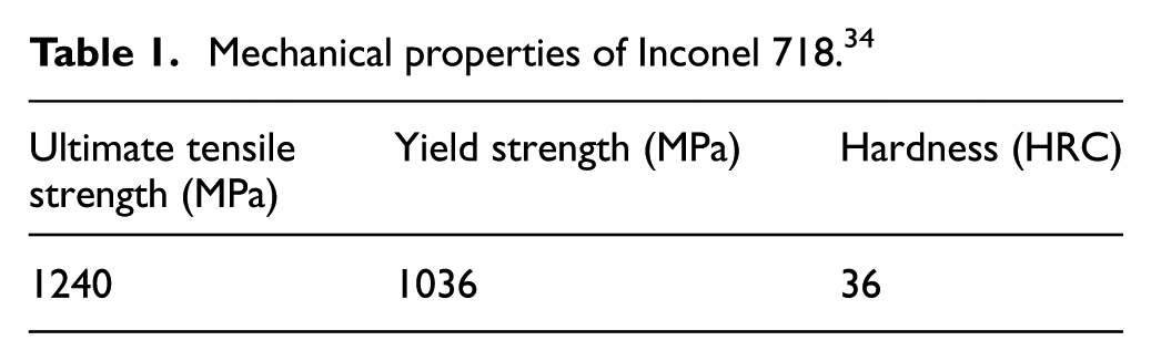
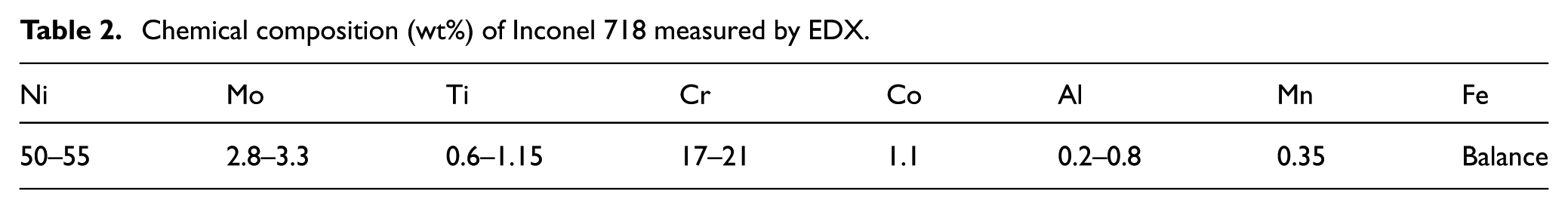
Inconel 718 was selected as the workpiece material for this investigation. The mechanical properties of Inconel 718 are presented in Table 1. The chemical composition of the workpiece material was measured by energy dispersive X-ray spectroscope (EDX; Table 2).
Mechanical properties of Inconel 718. 34
Chemical composition (wt%) of Inconel 718 measured by EDX.
Cutting tool
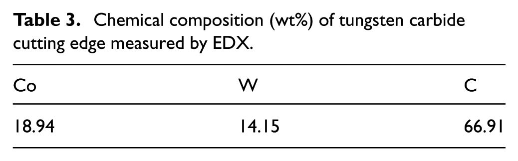
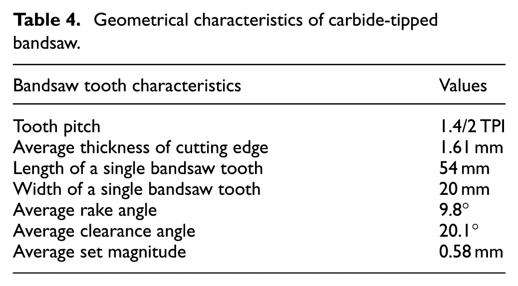
Single bandsaw teeth made of tungsten carbide tips were employed for the machining tests. Figure 1 presents a schematic diagram of a bandsaw tooth highlighting the tooth geometry. The tooth geometry is designed to efficiently cut large and difficult-to-cut materials such as Inconel for production cutting end users. High-grade backing steel and carbide tip materials in the teeth with optimum cutting edge produced by fine grinding give superior workpiece surface finish, maximum tool life and premium bandsawing performance. All teeth were examined under an optical microscope and a scanning electron microscope (SEM) for identifying any defects. The chemical composition of the carbide tooth was measured by EDX (Table 3). The geometrical features of the bandsaw teeth were measured by a shadowgraph, and average values are presented in Table 4.
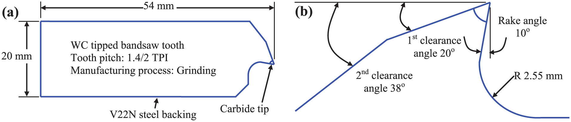
Schematic diagrams of (a) bandsaw sample and (b) carbide tooth tip geometries.
Chemical composition (wt%) of tungsten carbide cutting edge measured by EDX.
Geometrical characteristics of carbide-tipped bandsaw.
Cutting test procedure
It is well recognised that metal cutting testing and hence the acquisition of useful data for tool evaluation and tool design and development is time consuming and costly. The problem is further exacerbated when attempting to gather useful data by carrying out scientific tests on tools having more than one cutting edge. As a multipoint cutting tool, it is not very convenient to conduct full product testing of bandsaw owing to the high cost associated with the workpiece, lengthy machining time and complexity of extracting information from the measured data. At the moment, no national or international standard for bandsaw performance testing is available. From the manufacturing point of view, even the most rigorous quality control system will not be able to maintain the consistency in tooth geometry in every single tooth of a band with hundreds of cutting edges. Therefore, it is not surprising that bandsawing test results obtained from blades using commercial bandsaw machines will vary. The performance and life of bandsaw blades can also be influenced by the bandsaw machine characteristics (machine dynamics) and operating parameters (feed and speed). This could influence test data and contribute to inconsistency in the test results. As a general practice, time per cut as well as monitoring indirect parameters such as increase in cutting forces, or amount of run-out of the saw kerf from the vertical plane are often used as bandsaw performance criteria. However, this only gives global data, which is difficult to apply to individual tooth. Therefore, a single tooth simulation test representative of a full product performance test can give fundamental understanding of cutting mechanism, tool wear and so on and data required for optimising cutting conditions.
In this research work, the performance of carbide-tipped bandsaw tooth while cutting Inconel 718 was evaluated using a ‘single tooth technique’. 35 A schematic diagram of the machining test facility is presented in Figure 2. Separate workpiece sections were attached to the chuck to simulate the interrupted cutting action in bandsawing. Single tooth concept was also employed to understand other multipoint machining behaviour such as grinding of Inconel with a CBN grit. 36 A single tooth test needs to be fully representative of the ordinary bandsaw product testing. The results that are produced need to be meaningful in order to replace the full bandsaw testing. Previous research dealt with the initial cutting action of single bandsaw teeth and correlated the performance of single tooth to the performance of the full product. It was found that a single tooth test can be employed to simulate the initial cutting action of the full bandsaw. 35 However, despite having much similarity between the single tooth and full product tests, one should recognise some basic differences. For example, feeding bandsaw into workpiece is different in nature from that of a rigid lathe structure. The bandsaw can deflect under high feed rate pressure, which usually is not the case in more rigid set-ups such as lathe. In bandsawing, the depth of cut is determined by the force from the bandsaw and its cutting ability. Moreover, the width of the bandsaw can affect its cutting ability. Special attention should have been paid to the cross slide system in tool holder. Poor stiffness in the lathe cross slide system can produce backlash and hence there will be some degree of inconsistency in setting the depth of cut. Chips can move freely as no gullet was included in the single tooth and cutting takes place on the side of the workpiece in an open kerf situation unlike in actual bandsawing. These differences can affect the single tooth test results to some degree when compared with the full bandsawing.
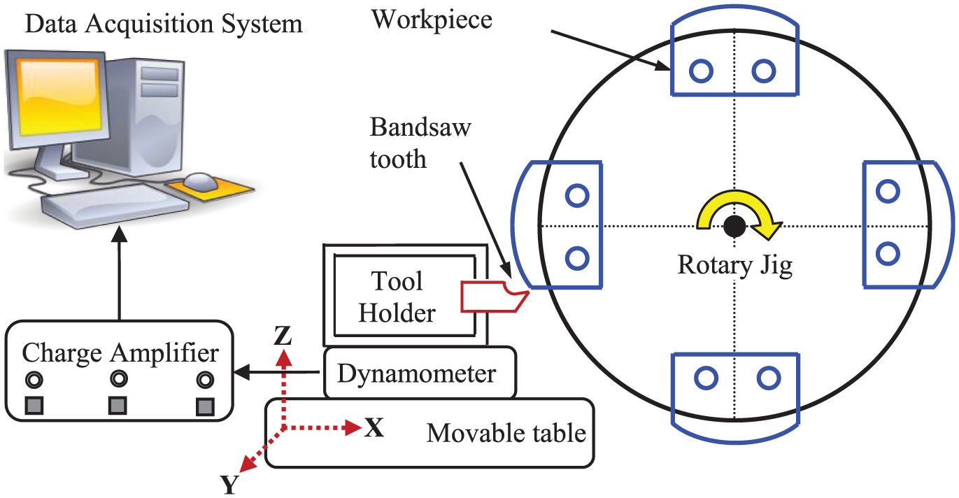
Schematic diagram of the machining test facility.
Three different feeds per tooth or depths of cut (10, 20 and 30 µm) with a constant speed of 30 m/min were chosen for the cutting tests. The width of cut was set to approximately 1 mm. Machining forces were measured during the bandsawing operation with a Kistler dynamometer and associated data acquisition equipment. Specific cutting energy was calculated from the force and material removal rate data. 27 The wear modes and mechanisms in the bandsaw teeth were investigated in the SEM. General characteristics of chips and their surface morphology were studied under an optical microscope.
Results and discussion
Characteristics of new bandsaw tooth
Figure 3(a) presents a typical SEM image of a bandsaw tooth, showing both the clearance and rake faces. The close view of the cutting edge appears to be free of any defects such as chipping. The average edge radius of the cutting edge was 13 μm when measured in the SEM. No sign of chipping was also observed in both rake and clearance faces. Horizontal grinding marks were clearly visible on the clearance face. However, no grinding marks were observed on the rake face due to an additional finishing operation performed during the bandsaw manufacturing process. This helps easy chip flow over the smooth rake face.
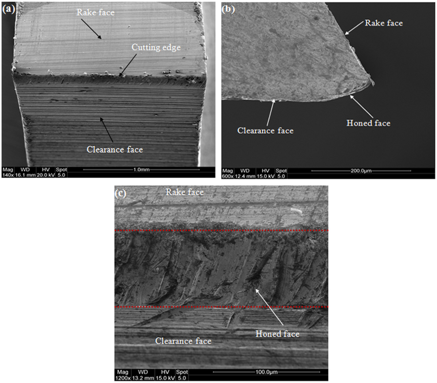
(a) Close view of the bandsaw cutting edge, (b) side view of honed face and (c) top view of honed surface.
During the manufacturing process, the carbide bandsaw teeth were processed by a special edge modification operation to produce a small flat on the cutting edge. A diamond pad was pressed against the teeth while the band travelled slowly. 37 On average, the operation created a flat length of approximately 120 ± 20 μm. The modified edge reduces the vibration at the beginning of cutting with a shorter running-in period and a much lesser chance of chipping the brittle carbide tip. The generation of flat was clearly visible from the side view of the magnified edge creating a new angle with the rake face (Figure 3(b)). However, the flat surface appeared to be substantially rougher than both the rake and clearance faces. The surface was characterised by ploughing marks created by the diamond particles (Figure 3(c)).
Wear modes and mechanisms of bandsaw tooth
SEM image of the worn bandsaw tooth clearly revealed that flank wear was the dominant wear mode (Figure 4(a)). The image also showed that chipping occurred on the rake face due to the interrupted nature of the cutting process. Furthermore, the flank wear at the right-hand corner of the tooth was more prominent than the rest of the cutting edge. This corner wear was caused due to the cutting action by the set tooth. Flank wear developed at the cutting edge due to the abrasive action between the flank face and machined workpiece (Figure 4(b)). There was also a clear evidence of adhesion of workpiece material onto the worn flanks promoting the adhesive-type wear. This is also evident from Figure 5, which shows adhering workpiece on the side face as well as on the flank face. Evidence of plastic deformation at the corner of the tooth was also found possibly due to the high mechanical and thermal stresses generated at the cutting edge.
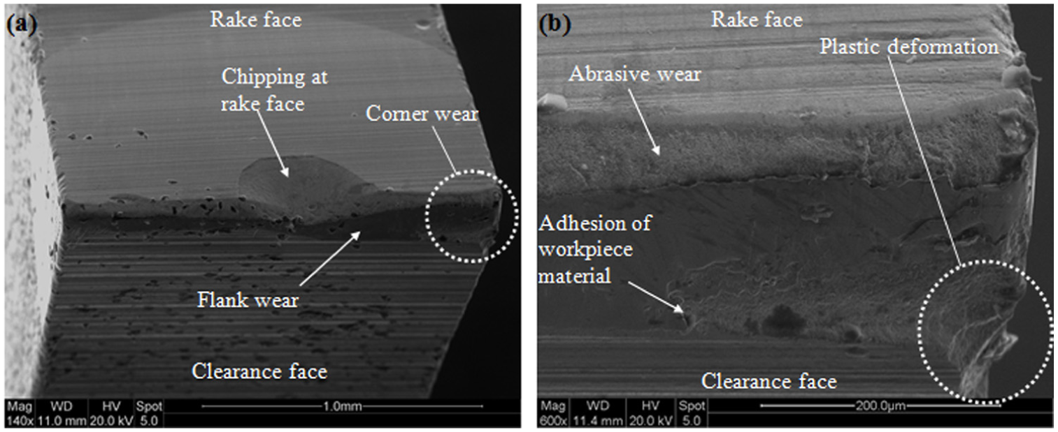
(a) Wear modes and (b) wear mechanisms in carbide-tipped bandsaw teeth.
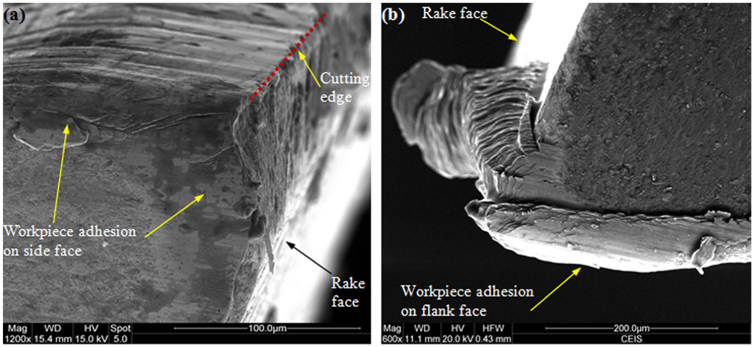
Adhesion of the workpiece (a) on the side face of tooth corner and (b) on the flank face.
The formation of micro-cracks in carbide tool is often observed in intermittent machining operation and has been reported previously. Micro-cracks observed in the bandsaw cutting edges (Figure 6(a)) could further extend into the carbide tip during prolonged machining and finally leading to chipping of the edge, thus modifying the tooth geometry.38–40 The micro-cracks around the region of chipping propagate and can lead to subsurface fatigue cracks during prolonged machining. Owing to the poor thermal conductivity of the Inconel 718, very little heat is carried away by the chips or workpiece material. Therefore, a high temperature is generated at the tool–workpiece interface leading to welding of chips with the cutting edge as seen in Figure 6(b). 41 The high chemical affinity of the Inconel further accelerates the welding and adhesion of the workpiece material onto the cutting edge. This welding process again accelerates the tool wear through the gradual removal of tool material with the chip during the machining process. Figure 6(c) shows that, in certain cases, the strongly welded chip can remove a big chunk of the tool material leading to a significant modification of the cutting edge. It was also noticed that after prolonged machining at high feed rate (30 μm), the carbide tip was completely detached from the backing material as evidenced in the SEM image of the broken tooth (Figure 6(d)).
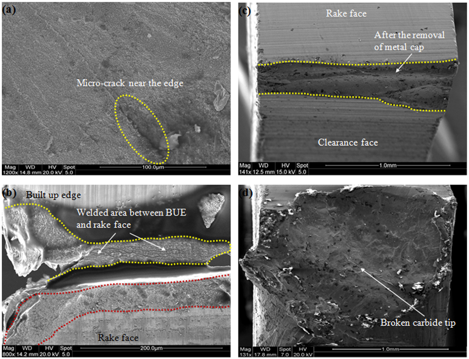
(a) Micro-crack formation on the rake face, (b) welded area between rake face and built-up edge (BUE), (c) cutting edge after removal of the BUE and (d) catastrophic failure of carbide tip.
BUE characteristics
After cutting approximately 500 sections (∼75-m length of cut), a metal cap or BUE started to form on the rake face of the tooth due to the welding of workpiece material by the high stress and temperature generated at the cutting edge (Figure 7(a)). As the machining progressed, the BUE gradually grew bigger in size as seen in Figure 7(b). The formation of BUE modified the cutting edge geometry leading to an effective blunt cutting edge with a higher edge radius, which would negatively affect the efficiency of the machining process. After continuing further cutting, it was observed that once the BUE reached a critical size, it was detached from the edge along with a fraction of tool material. This process further increased the wear at the cutting edge. Literature also reports the similar dynamic and cyclic BUE formation in three distinct stages (initiation, growth and breakage). 42 BUE formation can also be related to the periodic machine vibration possibly due to the significant reduction in the cutting ability of the modified cutting edge. The EDX analysis of the BUE revealed that the chemical composition of the BUE was similar to the workpiece material (Figure 7(d)). It was also interesting to note that on the rake face close to the carbide tip, the attached workpiece material apparently flowed in the gap between the BUE and rake face and formed a strong bond.
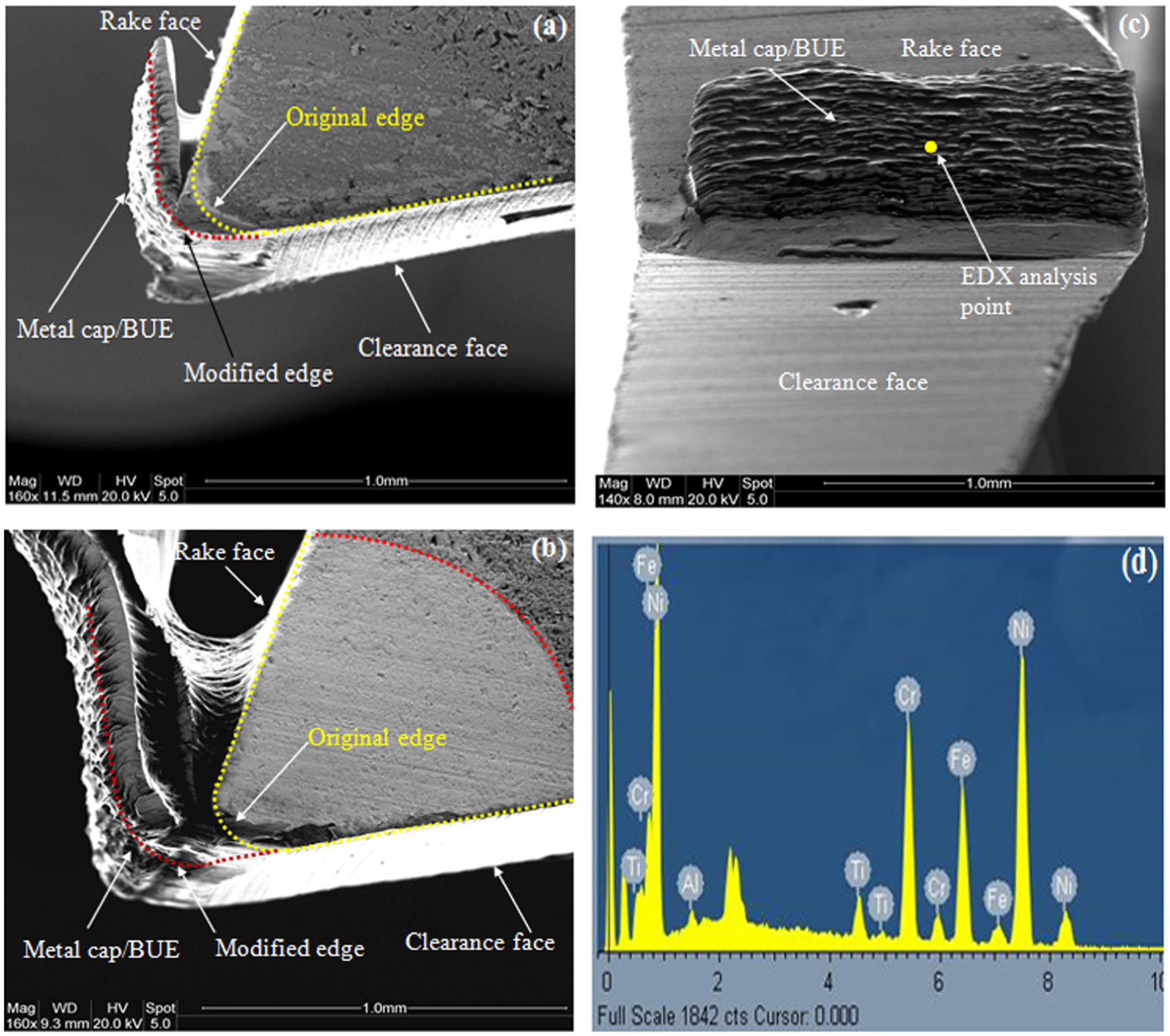
Metal cap or BUE formation due to the adhering of workpiece material to the carbide tooth when machining Inconel 718: (a) side view – starting of BUE, (b) side view – fully formed BUE and (c) top view of BUE and (d) EDX elemental map of BUE.
Chip characteristics
Chip formation mechanism plays an important role in determining the cutting forces, machining efficiency and the generation of the resulting machined surface. The chip formation mechanism in machining of Inconel 718 has been investigated in the past by a number of researchers.18,43–45 It is generally agreed that machining of Inconel produces serrated or saw tooth–type chips, which are very different compared to that formed during machining of conventional materials such as copper, steel and aluminium. The localised shear deformation in the primary deformation zone causes adiabatic shear, which is responsible for the formation of serrated chips. The chip formation process is influenced by tool geometry (e.g. edge radius) and the machining parameters (e.g. feed, speeds and depth of cut).
The cutting edge condition of the bandsaw affects the chip formation process. At the new condition of the tooth, sharp cutting edge led to the formation of continuous chips indicating an efficient cutting process (Figure 8(a)). However, short lumpy chips were formed when the cutting edge became blunt with a higher edge radius (Figure 8(b)). By observing the chips formed during bandsawing under the SEM, it can be seen that the back surface of the BUE (Figure 9(a)) is smoother and shinier compared to the free surface (Figure 9(b)). This can be attributed to the high contact stresses and friction between the rake surface and the flowing chip. 45 On the free surface and side of the chip, it was noticed that very thin and closely packed lamellas were formed possibly due to micro-level localised shear deformation (Figure 9(b) and (c)). In this case, the absence of pronounced serrated-type chips can be explained by the fact that depth of cut, cutting speed and the ratio between depth of cut to edge radius are much smaller in bandsawing compared to the conventional machining operations.
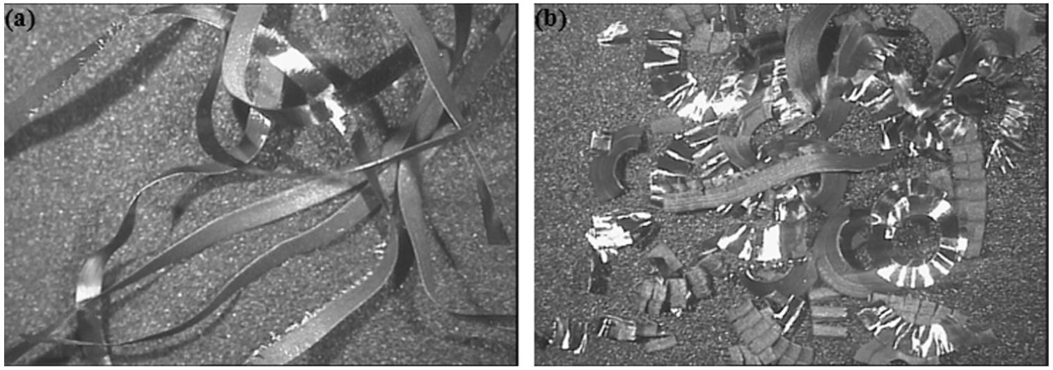
(a) Continuous chips and (b) fragmented chips generated at the new and worn conditions of the bandsaw teeth, respectively (magnification ×10).
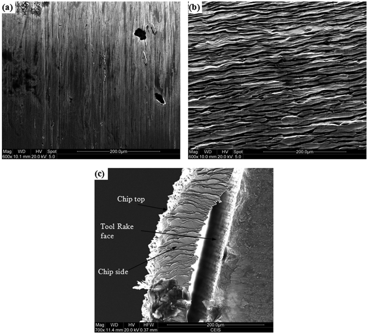
Chip surface morphology: (a) top surface (not in contact with rake face), (b) rear surface (in contact with the rake face) and (c) side view.
Cutting force measurement
It is a well-known fact that forces are strong indicator of cutting performances such as tool wear, surface finish and specific cutting energy. The development of cutting forces in the bandsaw teeth during the selected length of cut (150 m) at different feeds or depths of cut is plotted in Figure 10. The force components increased steadily with the length of cut, which indicated the gradual degradation and wear in the cutting edge. At the beginning of the machining test, the tool edge is relatively sharp and hence produces lower cutting forces. 46 As the test progresses, the edge wear increases leading to a blunt edge with increased contact area between the edge and the workpiece and also produces higher cutting forces. Therefore, the forces served as a good indicator of the degradation of the cutting edge throughout its life. Similar results were found by Sarwar et al.25,26 during the machining of steels with HSS bandsaws.
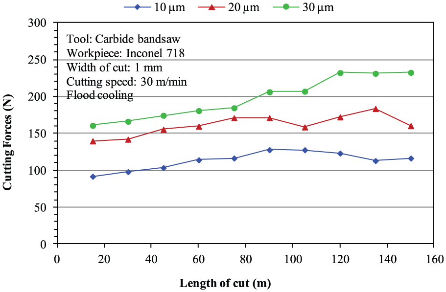
The variation in cutting forces with the length of cut at different depths of cut.
It was also noticed that at 10-µm depth of cut, the cutting forces reached the peak point after cutting 90 m and then gradually decreased to lower values. It was evident that after cutting approximately 75 m, the workpiece material started adhering to the rake face forming a metal cap or BUE (see Figure 7). The BUE modified the geometry of the cutting edge (i.e. blunting and formation of higher edge radius) leading to higher forces in the tooth. Once the BUE was removed from the cutting edge, the forces started to decrease owing to the improved condition of the cutting edge or a decrease in the depth of cut resulting from chipping or fracturing of the cutting edge.3,46 However, the forces at this point were still higher than the forces experienced by the carbide tooth at the start of the cutting operation possibly owing to the wear or chipping taken place at the cutting edge. Similar fluctuations in the cutting forces were also noticed during the tests with the other depths of cut employed.
The variation in force ratio (cutting force, Fc/thrust force, Ft) with the length of cut is shown in Figure 11, and it is considered an important parameter since it can affect tool performance, tool wear and surface integrity of the machined surface. In all cases during the machining tests, the force ratio was less than one suggesting that the thrust force was higher than the cutting force. A number of factors can be associated with this unusual phenomenon with respect to bandsawing.
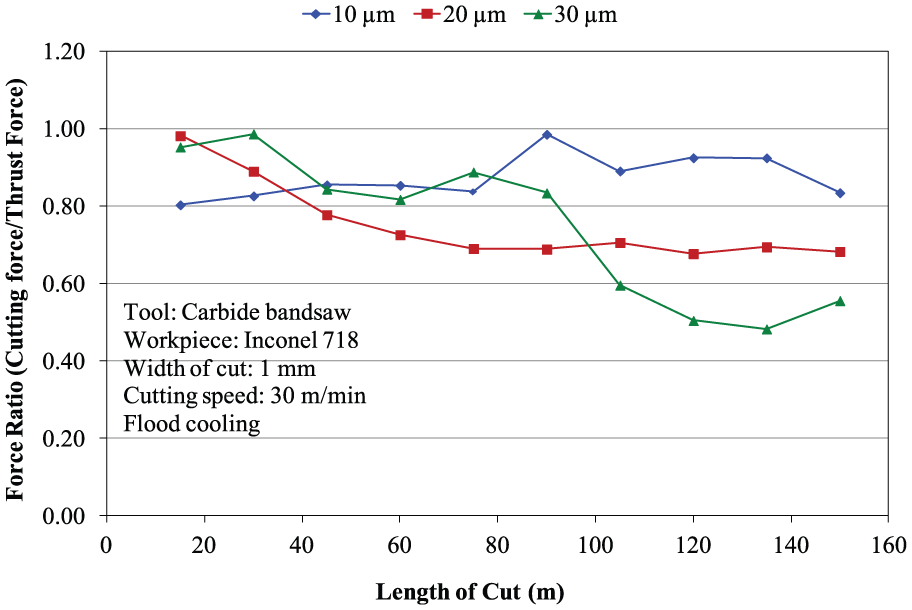
The variation in force ratio (cutting force/thrust force) with the length of cut at different depths of cut.
First, it has been established that a rubbing or ploughing action could take place in the close proximity of the cutting edge, which in practice is not perfectly sharp. 47 This is the case in bandsawing where edge radius could be equal to or higher than the depth of cut. The wear generated on the cutting edge leads to edge blunting with further increase in the edge radius. This results in a substantial increase in the thrust force component owing to the increased rubbing or ploughing action by the blunt edge. 46
Second, the carbide bandsaw teeth in question have already a small flank ‘wearland’ owing to the honing operation. This could be responsible for higher thrust force than the cutting force even at the beginning of the cutting operation. With the increase in the cutting length, the extended flank wearland led to even higher thrust force. Furthermore, it has been established that the thrust force is more sensitive to flank wear than the cutting force component, and therefore, the greater is the flank wear, the higher is the thrust force.
Finally, the unique material characteristics of Inconel 718 could also play a role in showing force ratio smaller than 1.45,48–50 A number of studies in the literature8,9,23,51,52 confirmed that Inconel 718 is sensitive to strain rate and gets rapidly work hardened. It was also found that the work hardening effect could be pronounced when the cutting tool is worn, 53 thus making the removal of material even more difficult. The combination of higher edge radius compared to the depth of cut and worn tool condition in bandsawing can cause workpiece surface hardening and thus making the tool penetration into the workpiece difficult.
Specific cutting energy
Specific cutting energy (Esp) is defined as the energy required to remove a specific volume of workpiece material. Esp is a quantitative way of measuring machining efficiency and can be used for assessing the condition of the cutting edge during cutting operation. 27 The Esp parameter is particularly suitable for measuring bandsawing efficiency due to the low depth of cut compared to the bandsaw edge radius. Figure 12 presents the variation in specific cutting energy with the depths of cut at different cutting lengths. It is very clear from the figure that higher depth of cut reduces the specific cutting energy or improves the bandsawing efficiency. On average, a 45% decrease in the specific cutting energy was observed with the increase in the depth of cut from 10 to 30 μm. However, it should be noted that higher depth could result in a premature failure of the bandsaw teeth. This condition is not desirable in practical bandsawing point of view due to the fact that the failure of one tooth in a bandsaw loop can cause catastrophic failure of the entire bandsaw loop. It was also observed that Esp at a particular depth of cut increases with the length of cut due to the wear and degradation of the cutting edge. Esp is also more sensitive to a lower depth of cut as evidenced by a greater change in the Esp values at 10 µm depth of cut compared to that at 30 µm. At 10-µm depth of cut, cutting edge radius is equal to or even higher than the depth of cut.
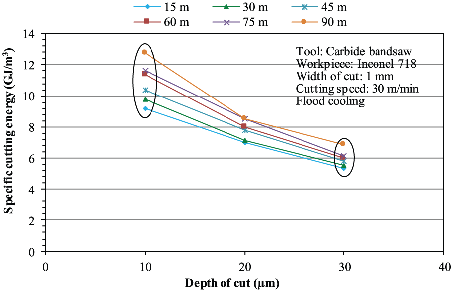
The variation in specific cutting energies with the depths of cut at different lengths of cut.
The higher depth of cut (30 μm) is clearly beneficial in terms of machining efficiency but not suitable for machining Inconel 718. This can be explained by the fact that at a higher depth of cut, a combination of high cutting force and heat generated in the cutting tool causes the rapid degradation of the cutting edge and finally catastrophic failure of the tooth results. However, at a lower depth of cut, tool life can be significantly extended. Therefore, based on the Esp results obtained with the range of parameters investigated, it can be concluded that depth of cut in combination with the other fixed cutting parameters should be lower than 20 µm in order to achieve the reasonable productivity with minimum tool failure.
Conclusion
Comprehensive machining tests were carried out with carbide-tipped bandsaw teeth in a specially designed test facility to ascertain the bandsawability of Inconel 718. During the machining tests, flank wear was identified as the dominant wear mode and evidence of chipping on the rake face and corner wear were also found. The mechanisms of flank wear involved a combination of abrasive and adhesive wear with some degree of plastic deformation. A BUE formed during the course of a machining test and increased the edge radius leading to an increase in the force components and a reduction in the machining efficiency. Although with the removal of the BUE, the force components decreased periodically, the carbide tip geometry was significantly altered due to the loss of edge material through chipping or welding with the BUE. The formation of micro-cracks on the cutting edge leading to chipping or fracture also played a significant role in the degradation of the carbide teeth. The wear and degradation of the cutting edge was indicated by the general trend of continuous increase in the cutting forces and specific cutting energies with the length of cut. The effect of the wear in the cutting edges was also observed through the change in generation of continuous chips at the new condition of the cutting edge to short lumpy chips at the end of the cutting test. Furthermore, it was evident that selection of higher feed could improve the machining efficiency due to the reduction in specific cutting energy; however, this could cause premature failure of the carbide tip in the bandsaw tooth.
It should be noted that this preliminary bandsawability investigation was limited to only one cutting speed setting, which is generally used for practical bandsawing of the Inconel 718. In future, the effect of a full range of cutting speeds will be explored.
Footnotes
Declaration of conflicting interests
The author(s) declared no potential conflicts of interest with respect to the research, authorship and/or publication of this article.
Funding
The author(s) disclosed receipt of the following financial support for the research, authorship, and/or publication of this article: This work was supported by the SNA Europe and Northumbria University, UK.