
Abstract
In self-propelled rotary tool machining, a circular cutting tool insert is used that continuously rotates about its axis during machining, as the tool is fed into the workpiece. The continuous rotation of the insert allows the insert to cool between engagements and improves tool life. In order to make use of this methodology for rough machining and bulk material removal in machining of aerospace materials, a self-propelled rotary face milling cutter is developed at Defence Research and Development Laboratory, Hyderabad. This cutter was developed to study the influence of inclination angle on the cutting forces generated during machining, and hence the cutter is provided with the provision to have the inclination angle of the insert for 20°, 30°, 40° and 50°. This article discusses the performance of the developed self-propelled rotary face milling cutter in face milling of titanium alloy at different inclination angles. The cutting forces developed in FX, FY and FZ directions are evaluated at different cutting speed, feed, depth of cut and inclination angles. The cutting forces obtained in self-propelled rotary face milling cutter is compared with that of conventional face milling cutter and the results are presented and discussed. Finally, regression models for prediction of cutting forces are developed.
Keywords
Introduction
In rotary tool machining, a circular profiled cutting tool insert is used. Unlike conventional milling with circular profiled tool insert, in rotary tool machining, the insert continuously rotates about its axis, as the tool insert is fed into the workpiece during machining. The continuous rotation of the tool insert allows each portion of the tool insert to rest and cool between engagements. This motion is in addition to the usual motions of cutting speed and feed relative to workpiece. Thus, rotary tools employ continuous indexing of cutting edge to enhance tool life during machining. In this rotary tools, the cutter axis and the cutting edge at the point engaging with the workpiece are inclined to the absolute workpiece velocity by the static inclination angle so that the forces and velocities during the chip formation will result in components tangential to the tool cutting edge which can propel the tool insert to rotate about its axis. Such tools are referred as self-propelled rotary tools. Alternatively, the cutting edge motion may be provided from an external source leading to driven rotary tool. In late 1950s, detailed investigations on kinematics of driven rotary cutting tool were carried out. It is stated that a rotary tool of 10° inclination angle is capable of reducing 30% of the total power required to make a cut by conventional method. 1 Later, in 1960s experiments were carried out on self-propelled rotary tool. It was found that the average tool–chip interface temperature decreased as the inclination angle increased in the self-propelled cutting process. 2 Venkatesh et al. 3 studied the effects of various machining parameters on tool life, surface finish and the type of chip generated during a face milling operation performed using a self-propelled round insert face milling cutter. The method of cutting that can be employed for cutting with rotary tools can be explained in two configurations—Type I and Type II. 4 In Type I, the orientation of the insert is such as to make the tool end face as the rake face. In Type II, the peripheral surface of the insert is the rake surface. Extensive investigation on the mechanics of driven and self-propelled rotary cutting tool processes was carried out. Force components, shear stress, friction angles, chip flow angles and chip length ratios were calculated and experimentally verified. It was also reported that the machining temperature in rotary tools operation is lower than that of machining with stationary tools.5–8 In rotary tools, because of the rotation of the cutting edge, the tool has a burnishing effect in addition to cutting. The unique movement of the tool and the combination of cutting and burnishing action distinguish the cutting process of self-propelled rotary tool from that of a conventional tool. 9 The rotary tools can be employed for machining of hard and “difficult-to-machine” materials such as titanium alloy used widely in aerospace applications.10,11
In metal cutting, the temperature generated in the tool–chip interface depends on the balance between the heat generation and the heat dissipation at that point. In conventional metal cutting, the consumed power is largely converted into heat. In rotary tool machining, some energy is required to drive the tool and is turned into kinetic energy. Thus, the heat generation is reduced. Moreover, nowadays, the use of cutting fluids is less desirable because of its adverse effect on the environment and human beings. In rotary tool, as the continuously rotating cutting edge distributes the cutting temperature along the entire cutting edge, these tools can be used for dry machining. It is recommended in the literature for dry machining to avoid biological and environmental hazard due to coolants. 10 Rotary tools have been applied in turning, facing, shaping and face milling operations.
Due to certain benefits of rotary tools in machining of exotic materials for aerospace applications, a self-propelled rotary face milling (SPRFM) cutter was designed and developed at Defence Research and Development Laboratory (DRDL), Hyderabad. 12 SPRFM tool can be used at much higher cutting speeds and feed rates than conventional cutting tools without significant adverse effect on the performance of the cutting tool and machine tool. The SPRFM process is only viable for oblique cutting configuration where the static inclination angle α is nonzero while the orientation (or sign) of α determines the direction of rotation of the self-propelled tools. The SPRFM cutter is designed with Type I configuration, that is, the orientation of the insert is such as to make the tool end face as the rake face. The pictorial representation of the SPRFM cutter–tool interface with Type I configuration is shown in Figure 1.
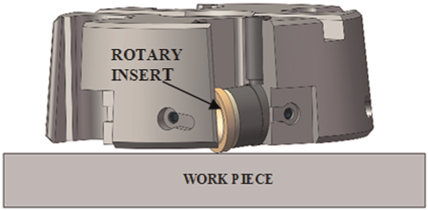
Schematic sketch of SPRFM cutter with Type I configuration and its workpiece interaction.
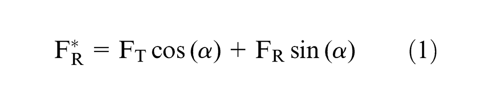
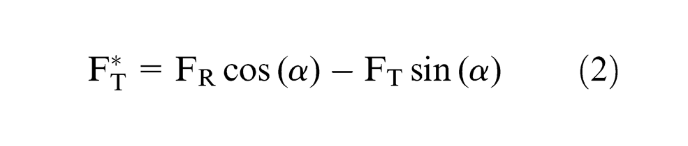
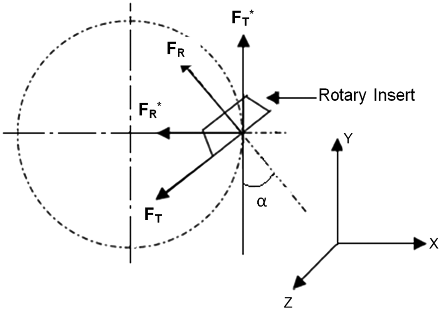
In face milling operation, the cutting forces can be resolved into three components—tangential force (FT), radial force (FR) and axial force (FA). Rake angles for milling cutters are specified in two directions, axial and radial. Axial rake is the cutting insert’s angle with respect to the central axis of the cutter/spindle assembly. Radial rake is the cutting insert’s angle with respect to the periphery of the cutter. The radial rake angle on a stationary insert in conventional face milling is considered to be inclination angle in rotary milling cutter which has great importance while dealing with the mechanics of rotary machining. Lead angle is the approach angle of the cutting edge as it enters the workpiece. The lead angle controls the direction of the radial cutting force and axial cutting force. When viewed from the side of milling cutter, the angle that is formed between the outer edge of the insert and the center axis of the cutter/spindle assembly is termed as lead angle. Mostly, the lead angle will be constant in face milling cutters. Lead angle has importance in chip thinning action and tool pressure. This lead angle is variable in the case of SPRFM cutter due to the circular edge of the insert and depends on the depth of cut provided. The diameter of the round insert used in a rotary tool operation is analogous to the tool nose radius of a stationary insert. The diameter of a round insert is usually very large (e.g. 27 mm) as compared to the tool nose radius which is usually of the order of 0.8 mm. The geometry of insert changes the geometry of cut and the lead angle on the milling cutter and consequently influences the cutting forces.13–15 As the lead angle changes, the cutting forces also changes. As the lead angle increases, the chip thickness decreases, but the length of contact (i.e. chip width) increases. Any increase in the lead angle also reduces or minimizes the breakout of material or burr. Hypothetically, when the insert is at the maximum depth of cut (i.e. one half of the insert diameter), the axial and radial forces are balanced. When the depth of cut is reduced, the radial forces decrease and the axial forces increase. At a very light depth of cut, the forces would be almost totally in the axial direction. The schematic diagram of the round insert and the lead angle is shown in Figure 2. Cutting forces in rotary milling operation are expressed into three components, that is, tangential force (FT), radial force (FR) and axial force (FA). In order to have rotary motion in the circular inserts, the inclination angle (α) is provided. Due to the influence of inclination angle, the forces can be resolved to obtain the effective tangential, radial and axial forces as follows 15

The effective axial force (
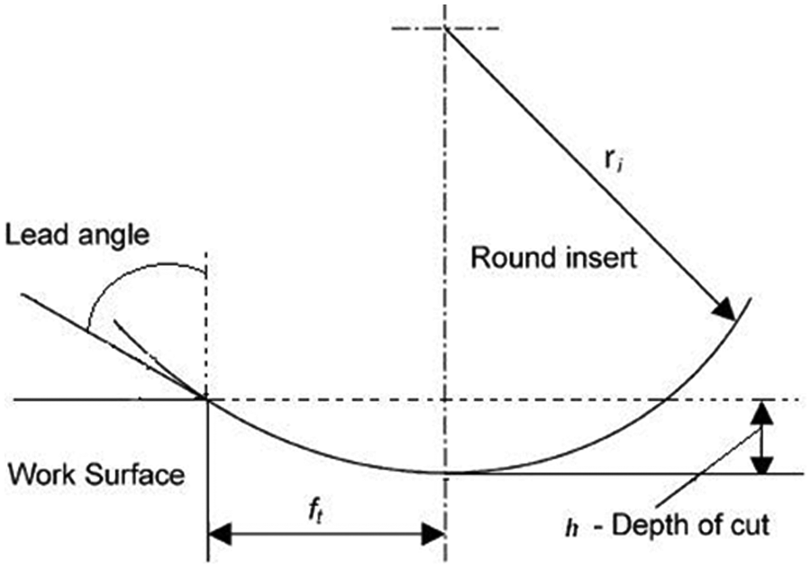
Lead angle on rotary inserts face milling cutter.
Effect of inclination angle on cutting forces in rotary face milling.
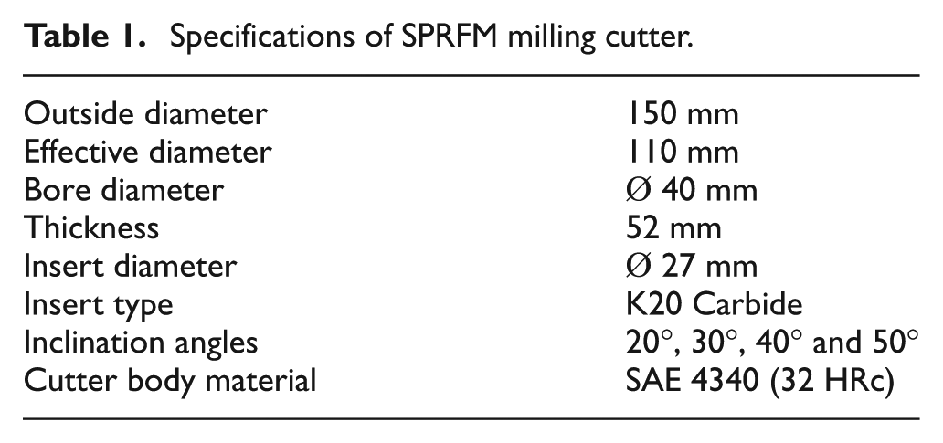
The SPRFM cutter is designed to have the rotary insert cartridges (M/s Rotary Tool Corporation, USA) at any of the four inclination angles—20°, 30°, 40° and 50° unlike the commercial cutter from M/s Rotary Tool Corporation with fixed inclination angle. Figure 4 shows the photograph of the SPRFM cutter developed at DRDL, Hyderabad. This cutter is useful to study the influence of inclination angle in face milling operation and also the effect of inclination angle in milling of different materials. The specifications of the rotary milling cutter developed in DRDL are given in Table 1. Figure 5 shows the actual cutting process by SPRFM cutting captured by a high-speed camera. A stable cutting with continuous chip formation is noticed in machining of titanium alloy (Ti6Al4V) with SPRFM cutter.
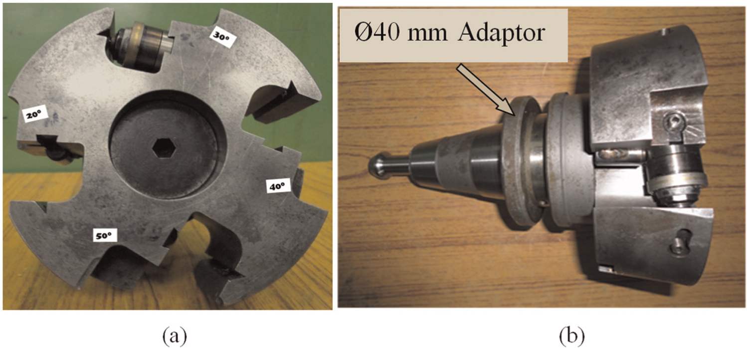
Photograph of SPRFM cutter developed at DRDL: (a) cutter body showing different inclination angles and (b) cutter with adaptor.
Specifications of SPRFM milling cutter.
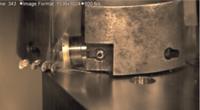
The chip formation with SPRFM cutter.
Experimentation
Experimentation methodology
In order to evaluate the performance of the developed SPRFM cutter and to study the influence of the inclination angles on machining of titanium alloy, full factorial experiments are planned to study the cutting forces in three perpendicular directions, that is, FX, FY and FZ considering the factors speed, feed, depth of cut and inclination angle. The levels of the factors considered for experimentation are shown in Table 2. In the experimentation, three levels are selected for the spindle speed, feed and depth of cut and four levels for the inclination angle. The cutting speed is derived from the spindle speed and the effective diameter of the cutter. The performance of this cutter is studied and also compared with that of the performance of conventional face milling cutter. Dry machining can be effectively used in open-faced operations such as face milling as the chips can be removed easily from the tool–chip interface. Considering the biological and environmental hazards due to coolants and to study the effectiveness of green manufacturing with rotary tools, during this experimentation, no coolants are used and the experimentation is carried out in dry machining condition.
Process parameters and their levels.
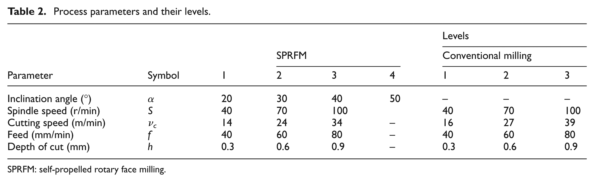
SPRFM: self-propelled rotary face milling.
Equipment, tools and material used
Experiments to study the cutting forces are conducted on a vertical machining center (VMC; Hinumerik 3100). The material used for investigating the performance of the cutter is titanium alloy Ti6Al4V with hardness of 32 HRc. This material is one of the most commonly used aerospace materials due to its attractive property of high strength-to-weight ratio. Also, it is one of the difficult-to-cut materials because of its unique machining properties such as high chemical reactivity and low thermal conductivity. The tools, equipments and material used are given in Table 3.
Tools, equipments and materials used.
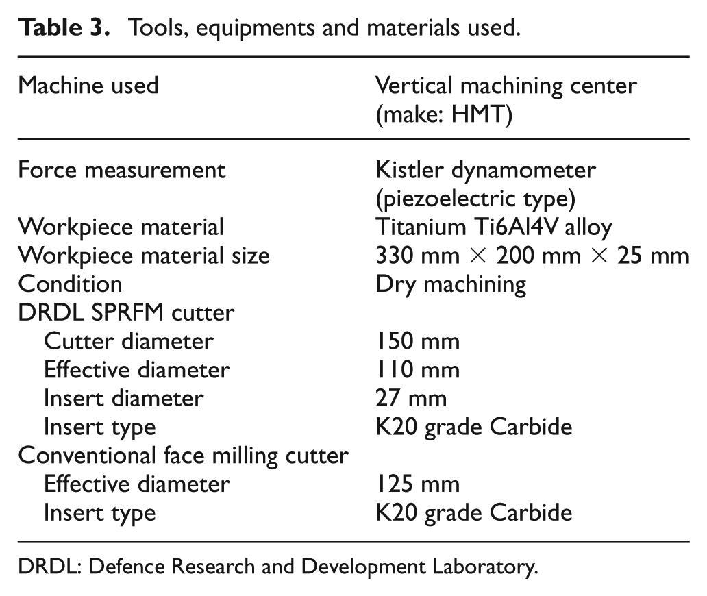
DRDL: Defence Research and Development Laboratory.
To measure the cutting forces, piezoelectric type 3 component dynamometer (make: Kistler, Switzerland; model: 9257B) was used. The work material is mounted on the dynamometer. The dynamic cutting force data were captured using a data acquisition system. The photograph of the experimental setup is shown in Figure 6.
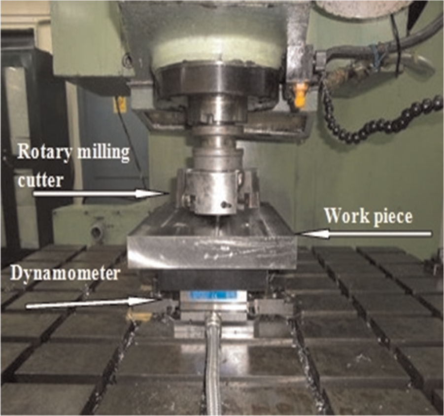
Photograph of experimental setup.
Results and discussion
Effect of parameters on cutting forces in SPRFM cutter
The variation in the cutting forces in FX, FY and FZ directions with the variations in speed, feed and inclination angle for depth of cut of 0.3, 0.6 and 0.9 mm is shown in Figures 7–9, respectively. It can be observed from the figures that as the feed and depth of cut increase, the cutting forces in all the three directions are increased. This could be due to an increase in the area of undeformed chip cross section with increase in depth of cut and feed rate. However, as the cutting speed increases, the cutting forces in all the three directions are decreased. This could be due to decrease in shear plane angle with increase in cutting speed. This is a common phenomenon that also occurs in conventional face milling operation.
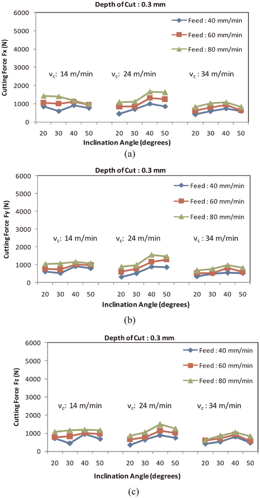
Variation in cutting forces with SPRFM cutter for depth of cut of 0.3 mm: (a) FX, (b) FY and (c) FZ.
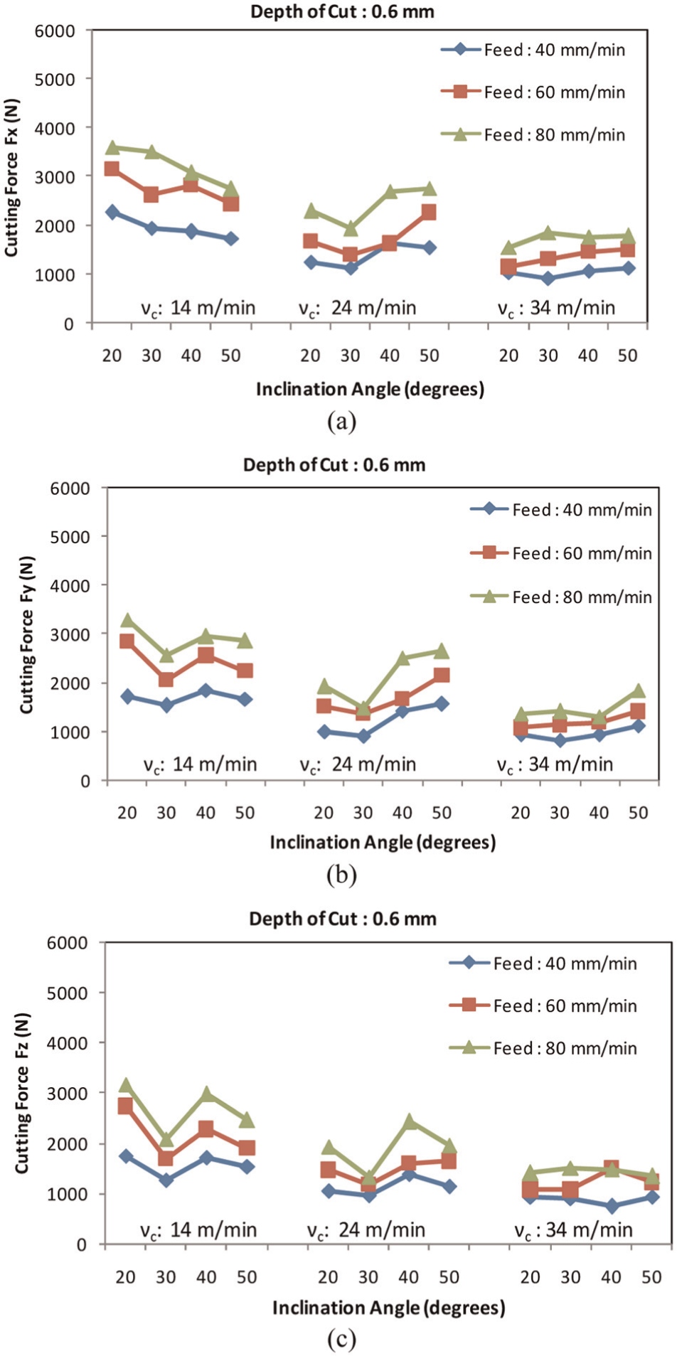
Variation in cutting forces with SPRFM cutter for depth of cut of 0.6 mm: (a) FX, (b) FY and (c) FZ.
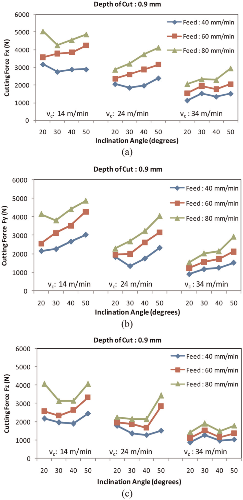
Variation in cutting forces with SPRFM cutter for depth of cut of 0.9 mm: (a) FX, (b) FY and (c) FZ.
However, it can be noticed that the inclination angle also influences the cutting forces during face milling. The influence of inclination angle is less significant in the case of low depth of cut. But its influence increases with increase in depth of cut. Mostly, these rotary face milling cutters are used in aerospace industry for machining at high depth of cut and feed rates. It can be noticed from the results that at high depth of cut and high feed rates, the cutting forces show low value for the inclination angle of 30° and 40° in most of the cases. Furthermore, the mean response curve for the cutting forces FX, FY and FZ as shown in Figure 10 depicts the trend in the cutting forces for variation in inclination angle, cutting speed, feed and depth of cut. The trends show that the mean cutting forces are low for the inclination angle of 30°. The decrease in the cutting forces can be attributed due to reduction of coefficient of friction at the chip–tool interface and free rotation of the rotary insert when compared with cutting with other inclination angles. This reduction in coefficient of friction and free rotation of the insert also results in smooth free cutting of Ti6Al4V alloy with continuous chips.
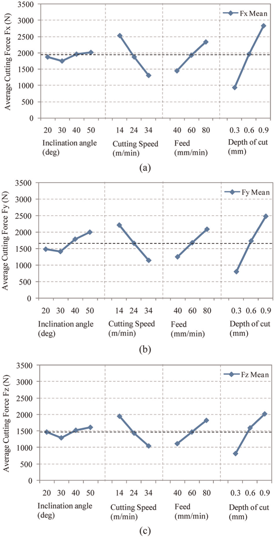
Mean response curve for cutting forces: (a)FX, (b) FY and (c) FZ.
Comparison of cutting forces obtained in SPRFM cutter with conventional face milling cutter
The variation of cutting forces with conventional face milling cutter at different combinations of input parameters is shown in Figure 11. The general trend of increase in cutting forces with increase in feed and depth of cut and decrease in cutting forces with increase in cutting speed is observed.
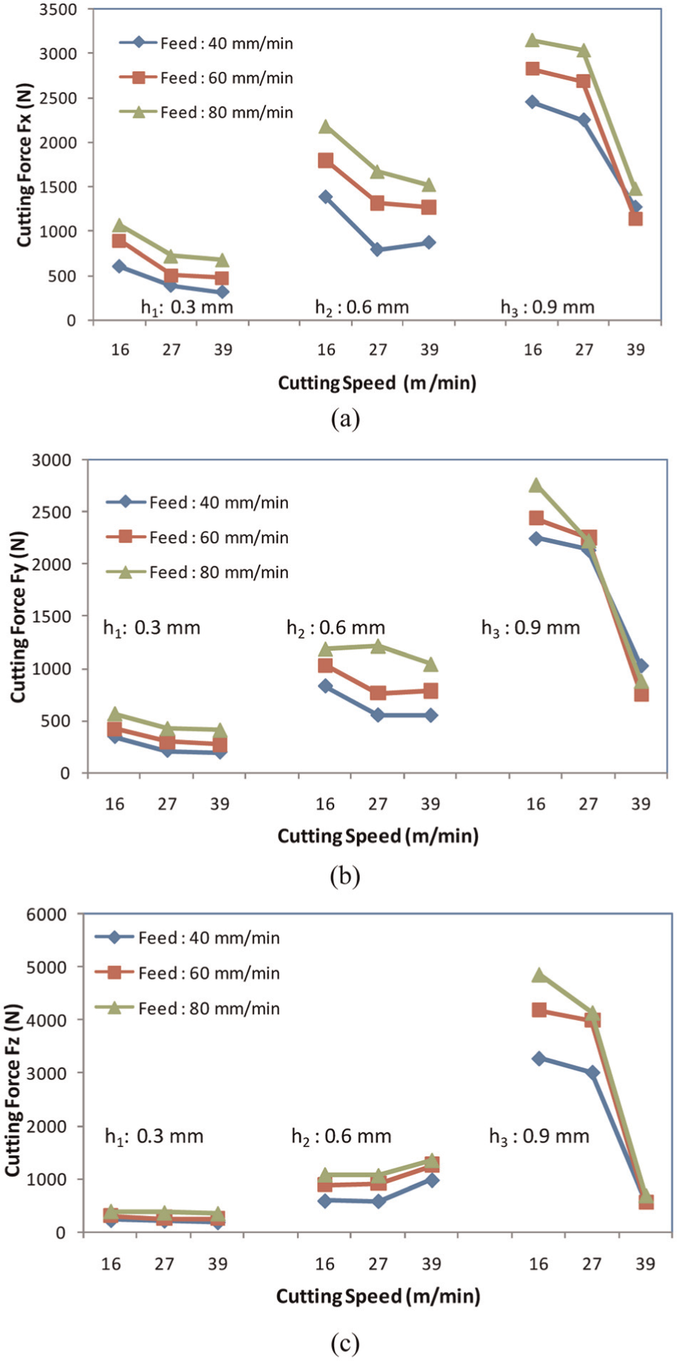
Variation in cutting forces with conventional milling cutter: (a) FX, (b) FY and (c) FZ.
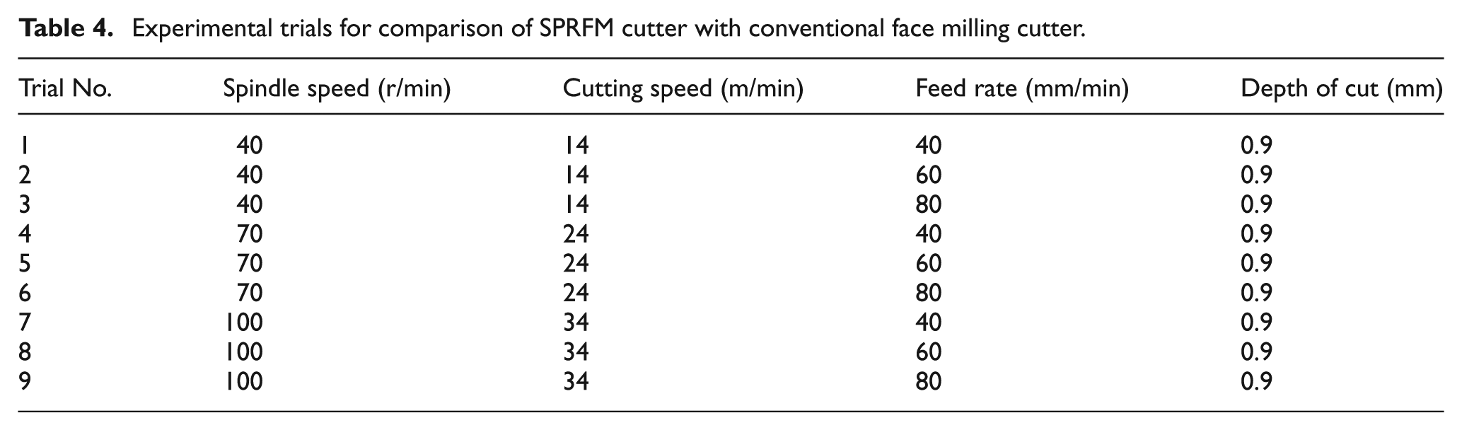
The data collected are employed for comparing the cutting forces obtained during face milling of titanium alloy with SPRFM cutter and conventional face milling cutter. Table 4 shows the list of experimental trials and the set of parameters considered for the comparison. In this data set, only the experimental trials with high depth of cut of 0.9 mm are considered for comparison. The comparison of cutting forces FX and FY observed in the case of SPRFM cutter and conventional face milling cutter is shown in Figure 12(a) and (b). The comparison of thrust cutting forces FZ is shown in Figure 12(c).
Experimental trials for comparison of SPRFM cutter with conventional face milling cutter.
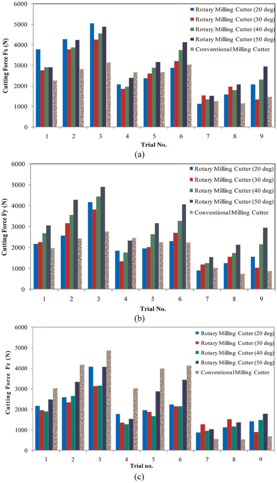
Comparison of cutting forces in SPRFM cutter at different inclination angles and conventional face milling cutter: (a) FX, (b) FY and (c) FZ.
From Figure 12(a) and (b), it can be observed that the forces FX and FY are high in the case of SPRFM cutter when compared with conventional face milling cutter. This could be due to larger nose radius in the case of SPRFM cutter. From Figure 12(c), it can be noticed that at low cutting speeds, the thrust forces observed in the case of SPRFM cutter are lower than the cutting forces obtained in conventional face milling cutter. But, at high cutting speed, the thrust forces are observed to be lower in the case of conventional face milling cutter. The higher cutting force in the case of SPRFM could be attributed to the increase in the frictional force from the work material for the rotation of the insert due to low thermal conductivity of material and high temperature buildup at the cutting edge leading to welding of chip to the insert and retards the rotary motion of the insert and also the smoothness of rotation. This reduction in insert velocity with respect to the propelling cutter speed leads to rubbing action in the cutting zone. However, the effectiveness of SPRFM at higher cutting speeds needs to be further investigated.
Development of regression equation models for cutting forces
In order to establish the mathematical relationship between the cutting forces FX, FY and FZ for various input parameters considered such as inclination angle, speed, feed and depth of cut, a second-order polynomial regression equation in the following form (equation (1)) is fitted 16
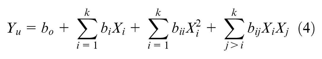
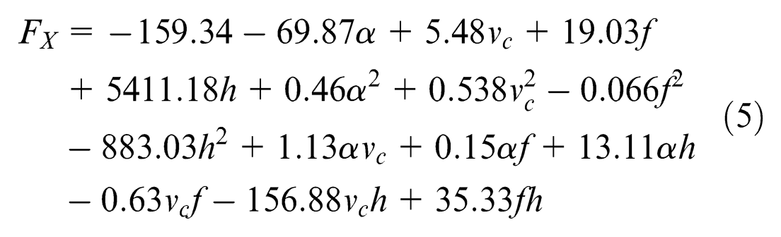
where Yu is the dependent variable or response and the Xi (1, 2, …, k) are coded level of k quantitative variables. The coefficients bo, bi, bii, bij are called regression coefficients. The coefficient bo is the constant term, the coefficients bi are the linear terms, the coefficients bii are the quadratic terms and the coefficients bij are the interaction terms. In the development of the regression model, the regression coefficients are estimated using SPSS statistical software package. The coefficients obtained and the regression model for cutting forces FX, FY and FZ are shown in equations (5)–(7), respectively
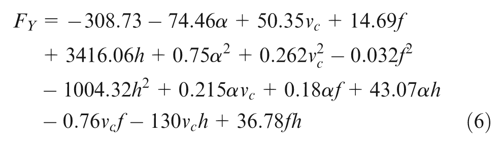
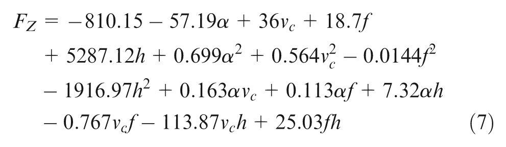
To analyze the effectiveness of these models for predicting the performance of the SPRFM process, coefficient of determination (R2) is calculated. The coefficient of determination (R2) is used to identify the closeness of fit. Figure 13 shows the comparison of the predicted cutting forces FX, FY and FZ with respect to the experimental cutting forces FX, FY and FZ. The estimated R2 value for cutting forces FX, FY and FZ are 0.9, 0.89 and 0.81, respectively. The estimated coefficient of determination R2 value indicates that the predicted cutting forces by the developed second-order regression model are in good correlation with the experimental values. The cutting force models can further be improved with the application of modern soft computing techniques.
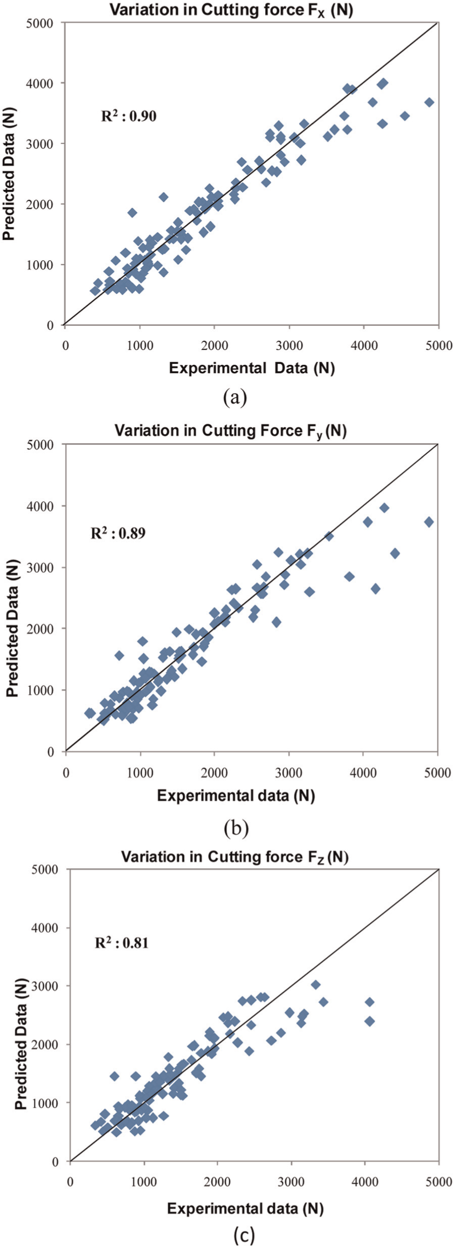
Comparison of predicted and experimental cutting forces: (a) FX, (b) FY and (c) FZ.
From this investigation, SPRFM cutters are recommended for bulk machining of difficult-to-machine titanium alloys (Ti6Al4V) for aerospace applications with inclination angle of 30° and at low cutting speed. Another merit in using the SPRFM cutter for machining of Ti6Al4V alloy is that it can be used at dry machining condition with considerable good tool life. Moreover, due to the rotation of the insert during cutting process, the surface finish can also be improved in machining with rotary tools. The regression models developed can be employed for predicting the cutting forces in machining of Ti6Al4V alloy with SPRFM cutter and to develop any control strategy to minimize the cutting forces.
Conclusion
Rotary tool machining has potential applications in machining of aerospace materials. In order to utilize this technology for machining of exotic materials, an SPRFM was developed by DRDL, Hyderabad. Experimental studies on the cutting forces (FX, FY and FZ) developed during machining of titanium (Ti6Al4V) alloy with the developed cutter for variation in inclination angle, speed, feed and depth of cut are carried out and the optimum inclination angle is obtained. The performance of the developed cutter in terms of cutting forces is compared with that of conventional milling cutter and found that SPRFM cutter generates lower thrust cutting force when compared with conventional face milling cutter for lower cutting speeds. Also, the regression equation models for cutting forces (FX, FY and FZ) are proposed. Finally, it is recommended that the SPRFM cutter is more suitable for dry bulk machining of difficult-to-machine materials such as titanium alloy for aerospace applications.
Footnotes
Acknowledgements
The authors wish to express their sincere thanks to the Director, Defence Research and Development Laboratory, Hyderabad, and staff, especially Mr P. Raghunandan, Junior Research Fellow for the support rendered to carry out this research work.
Declaration of conflicting interests
The authors declare that there is no conflict of interest.
Funding
This research received no specific grant from any funding agency in the public, commercial, or not-for-profit sectors.