
Abstract
In 3½½-axis machining, the machined part surface is partitioned in pre-processing in order to calculate the tool position and patch boundaries and then machined in patches, thereby minimizing the intermediate manual part re-positioning and the overall machining time. Each patch requires a constant, but different, tool orientation. In previous research, local properties have been used to subdivide surfaces into patches. For an ideal tool position and orientation, however, the tool’s shape and curvature should exactly match the shape and curvature of the part surface. The rolling ball method, originally developed for 5-axis machining, considers the regional characteristics of tool positioning. This work extends the rolling ball method to 3½½-axis machining, thereby successfully delivering 5-axis quality with currently installed 3-axis computer numerical control milling machines. The pseudo-radius of curvature provides a novel geometrical subdivision criterion. Two Bézier curved surfaces are tested and compared with the 5-axis rolling ball method. Two additional surfaces are presented to further demonstrate the partitioning capability of the method. The results suggest that the rolling ball method for 3½½-axis machining is comparatively competitive in performance and quality.
Keywords
Introduction
The so-called 3½½-axis machining combines the flexibility of positioning offered by 5-axis machines, as well as the low cost and ease of programming offered by 3-axis machines. Recent work has shown methods for 3½½-axis machining that resulted in time savings over 3- and 5-axis machining.1,2 Time savings are even being considered in high-speed machining. 3 These methods are based on the partitioning of the surface into patches and determining an adequate tool orientation and tool path strategy for each patch. The parameters used for partitioning include the surface coordinates and normal vectors, which provide only local information at the sample points. Nevertheless, tool orientation is a regional issue, and both the tool surface and the part surface must be considered for adequate or optimal tool positioning, as demonstrated by Warkentin et al. 4 The method developed by Warkentin et al., called multi-point machining (MPM), exploits the regional nature of tool position to find multiple contact points. However, the MPM is too complex in calculations. To address this issue, the rolling ball method (RBM) was developed to take into account additional information for each contact point, and then it evolved into a more robust method for tool positioning.
The RBM introduced by Gray et al.5,6 positions a spherical ball tangent to the point of contact of the cutter on the surface and inflates an imaginary ball until the ball contacts a second point on the surface, thereby obtaining the largest ball that can sit tangent to that point without invading the part surface elsewhere. Thus, the RBM closely relates to MPM but results in a changing radius of the ball at each matching point with a delta distance along the tool path. The ball approximates the surface in the neighborhood of the cutting tool. This imaginary ball encapsulates the tool and determines both the tool position and orientation at each step along the tool path. The regional nature of the RBM coupled with simplicity of its calculations makes it an ideal choice, even over MPM for use in the 3½½-axis machining.
The implementation of the RBM offers a novel option for surface partitioning in addition to extending prior work in tool positioning within the 3½½-axis machining method toolkit. The differences in the radius of the ball at each possible tool position provide a new geometrical criterion with which to identify the patches. The inflated ball represents the largest sphere that can sit at any point without gouging the surface at another point. After the surface is subdivided into patches, the RBM is again used to compute a gouge-free tool position at each point of the previously defined patches. The most inclined tool axis computed along the chosen feed direction is selected and set to be the tool orientation, orientation required to compute the tool path and to machine the considered patch, thereby avoiding any possibility of gouging.
In this article, we present the implementation of the RBM for 3½½-axis machining. This implementation uses the RBM for both patch partitioning and the determination of the optimal tool orientation for all points on each patch. The RBM can be applied for different types of surfaces, surfaces such as Bézier surfaces, scanned surfaces, or triangulated surface data, all of which can support a future industrial implementation. This improved method is tested with two different Bézier surfaces and compared—via machining time—with RBM for 5-axis machining. Two additional surfaces, one algebraic and one triangulated, are considered and presented but only in simulation to further verify the flexibility of the patch partitioning method.
Previous research has attempted to take advantage of the tool positioning of 5-axis methods without using the expensive 5-axis machines. Moreover, the complexity of determining the optimal or even adequate lead and tilt angles for each surface point in 5-axis machining is, itself, a challenging issue,7,8 thereby leading to implementation failures in 5-axis machining. When these pseudo 5-axis methods are applied to 3-axis machines, they are commonly based on a fixed tool orientation which is then optimized for machining a region with no tool or part re-orientation. The 3½½-axis machining strategies subdivide the surface into regions and find adequate tool orientations for those regions. 9 Ralph and Loftus, 10 Suh and Kang, 11 and Suh et al. 12 developed 3½½-axis machining strategies that can be conducted on 3-axis machines. Yet, these techniques require significant computer pre-processing and partitioning optimality is not guaranteed. Gray et al. 13 introduced a different approach called 3½½ axis arc-intersect method (AIM). AIM uses a tool orientation that is optimized for each tool pass and not for a specified region, thereby requiring a large number of orientation changes, changes that increase considerably the total machining time for indexable 5-axis machines. Ding et al. 14 employed the concept of “isophotes” and “light region” for surface partitioning, which partitions the region of sculptured surfaces into regions according to the slope obtained from the normal vector of the intersecting planes. Since the isophotes method relies on the “light regions” for partitioning a surface, in certain cases the “light region” can be both a concave region and a convex region, thereby making more complex the selection of the best cutting tool. Park and Choi 15 conducted a partitioning of a free-form surface employing the Z-map method, which yields partitions with similar slopes and curvatures. Radzevich16,17 presented an approach to divide a surface into cutter-accessible and cutter-not-accessible regions, which was only convenient for particular cases, but his method was extended for all the cases of smooth, regular, and free-form surfaces employing multi-axis machining. Safka et al. 18 and Van Tuong and Pokorn 19 also partitioned free-form surfaces into convex, concave, and saddle regions based on the Gaussian curvature and the mean curvature. Other more recent 5-axis machining path smoothing techniques such as Bézier smoothing 20 and local jerk smoothing 21 are not compatible with 3½½ machining.
Significant prior work developed by our group follows the concept proposed by Chen and extended by Roman et al. 1 Both methods categorize regions with similar surface properties by employing the existing clustering algorithms. Although both methods confirmed the effectiveness of 3½½-axis machining, they also revealed limitations, limitations that included the use of local parameters. To avoid this, this work replaces the partitioning parameters with the radius of the contact sphere obtained via the aforementioned RBM. This modified version of the RBM provides information of the shape and radii of curvature for each contact point. The theory and implementation will be presented in the following two sections followed by a section which presents the experimental results.
Theoretical framework of the RBM
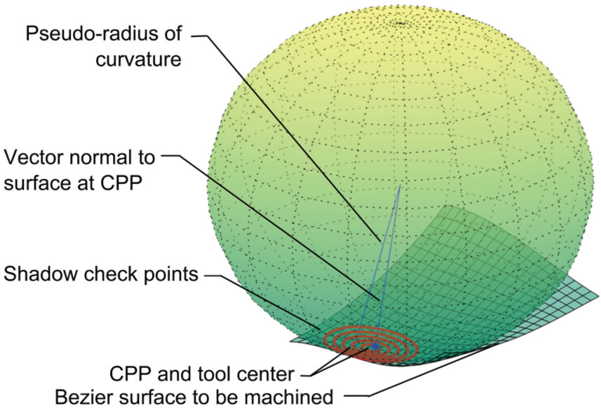
The RBM approximates the surface around the machining point with an imaginary portion of a sphere. The tool is placed inside this sphere in order to make coincident the cutter contact point (CCP) and the machining point. The radius of the sphere is determined by the largest ball possible prior to establishing a second point of contact and prior to surface gouging in the vicinity of the surface. This portion of surface is called the shaded area or the region where the tool casts a shadow. For each point on this shaded area, the radius of the ball creates a pseudo-radius for secondary contact point evaluation. At the contact point, the sphere fits the local surface without gouging the surface anywhere, although it leaves excess material elsewhere up to the established epsilon thickness. Now the tool can be positioned and oriented within the sphere such that it forms a circular line of contact. 22
Shaded area
The part surface area located inside the shadow of the tool represents both the region of the tool and the surface that must be taken into account when computing a gouge-free tool path. The size and location of this area depend on the tool’s positioning and its final orientation and are therefore over-estimated. The shaded area is divided into five concentric circles called “shadow circles” and each comprises 100 data points, called shadow-check points, as shown in Figures 1 and 2. Additionally, Figure 2 shows the CCP, the pseudo-radius of curvature, and the estimated tool center. The sphere represents the rolling ball. Afterward, the pseudo-radius of curvature is computed for each of these shadow-check points.

Shadow area (top view) is an over-estimation of the tool contact area in order to ensure a gouge-free path.
Shadow area showing the desired Bézier surface and the shadow-check points in concentric circles overlaid on the surface.
Pseudo-radius of curvature
The pseudo-radius of curvature is defined as the radius of the circle whose center lies on the surface normal, normal to the CCP, and the circle passes through both the CCP and each of the shadow-check points. 5 For each one of the CCPs, the pseudo-radii are calculated in each of the shadow-check points; afterward, the radii are compared in order to identify the most concave radius possible. The most concave radius is selected to be the pseudo-radius of the sphere that will be employed in the tool path generation. Figure 2 shows, and equation (1) gives, the pseudo-radius of curvature

where
Tool positioning
Tool positioning cannot be considered only as a local because the cutting tool can affect the area surrounding the contact point. This regional nature of tool positioning is the foundation for the RBM. Warkentin et al. 4 show that any toroidal or flat-ended cylindrical tool, when placed inside a sphere, forms circular line of contact, thereby guaranteeing a gouge-free tool path. Unfortunately, there is an infinite number of ways to position the tool into the sphere. Yet, there is only one contact point between the sphere and the surface, and the cutter contact point (CCP) is defined by this intersection; hence, the contact between the tool and the surface is ensured at that one point. Tool position also depends on the sign of the curvature. For a positive curvature, the tool is positioned inside the ball, and for a negative curvature the tool is placed outside the sphere, as shown in Figure 3(a) and (b), respectively.

Positioning the tool outside or inside the sphere for either negative or positive curvature machining: (a) tool inside for positive curvature and (b) tool outside for negative curvature.
In the RBM, the tool is positioned at the contact point and maintains a circular line of contact with the ball.
5
Inside the sphere, the tool center position (

Equation (4) defines the distance to the tool center (“

Calculating the “
The vector

The previous section gave a brief description of the RBM, but a more detailed description can be found in Gray et al.5,6
Methods
The following section describes the extended RBM for 3½½-axis machining, which includes the clustering algorithm for subdividing the surface into patches, the tool path generation method, and the experimental setup designed to compare the performance of the proposed 3½½-axis machining method against the conventional 5-axis machining.
Extension of the RBM for 3½½-axis machining
The first step of the RBM consists of extracting the pseudo-radii for a set of sample points. These pseudo-radii describe significantly the shape of the geometry that will be divided. Additionally, the spatial location of the sample points is described using the surface coordinates. In the second step, the clustering algorithm employs the pseudo-radii and the surface coordinates to calculate the surface patches; subsequently, these will be machined separately and with the most suitable feed direction, tool orientation, and step-over. We choose to employ the RBM for tool path planning because we had already implemented it. Nevertheless, other path planning techniques such as curvature, isophote, configuration, or polyhedral-based techniques could be employed. 9 The tool path is generated for both machining within a patch and the indexing movement from the current patch to the subsequent one. Although the RBM can subdivide a surface into a specified number of patches, it does not necessarily yield the optimal number of patches, thereby resulting in the shortest machining time. Hence, calculating an adequate number of patches currently requires dividing the surface into a varied number of patches for subsequently calculating the machining time for each patch. The third step consists of calculating the machining time required for a range of patches defined by the user off-line or in pre-processing (although this could be automated in future work). Afterward, the partition with the smallest machining time is selected as adequate for the final tool path.
Clustering
In this work, the geometrical criteria used for clustering are the surface coordinates and the pseudo-radii versus prior work that only used surface coordinates. The surface coordinates provide information about the location of the point required not only to maintain the neighboring points in one patch but also to avoid disjointed patch boundaries. These disjointed patches can lead to machining defects on the patches’ boundaries. The pseudo-radii provide data used to group points on the surface where the curvature is similar, and thus, this can be machined using the same tool orientation and varying only the tool position in three axes.
The first step in the clustering process is to calculate the rolling ball radius for each sample point. The RBM algorithm employs the surface coordinates and the surface normals to compute the pseudo-radii of curvature for each point of the 500 points of the shaded area. The second step consists of creating a feature vector employing the surface coordinates and the corresponding pseudo-radii. This feature vector is normalized and used as the input to the standard k-means clustering algorithm. Chosen for implementation simplicity, the algorithm divides the data set into a predetermined number of patches. The objective function that the algorithm employs is based on the square-error distance as defined by equation (7)

where
The k-means algorithm starts by randomly positioning
Tool path generation
Once the surface is subdivided, the tool path for each patch must be generated. The generation process of tool path starts by finding the optimal tool orientation and feed direction. The calculation of these two parameters is performed employing the projection of the surface normals of each patch into a two-dimensional (2D) plane. The area comprised by the surface normal is approximated using common statistical tools. This strategy is developed to minimize the deviation between the tool axis and the surface normals within a patch, thus allowing a better match of the tool’s geometry to the part surface. This close match of the tool’s geometry results in a larger step-over between passes and a shorter overall tool path length, thereby reducing total machining time.
The example below shows the method developed for finding an adequate, if not the optimal, feed direction and tool orientation per patch. After the surface subdivision, each patch is composed of a group of sample points. Each sample point contains the surface coordinates and the normal vectors. The projection of the surface normal is obtained by moving the normal vectors of the patch’s points to the same origin. The tips of the surface normals are projected to a 2D plane and then approximated by an ellipse, which fits the data, within one sigma, as shown by Roman et al. 23
The parameters of the ellipse are defined by the eigenvalues (

Projected surface normals plane.
After defining the projection of the normal vectors and the ellipses, the feed direction is determined using one of the two axes of the ellipse. If the feed direction is determined by the minor axis (
Once the feed direction for each patch is calculated, the tool axis position for each sample point is computed employing the method described above. This process starts by determining the most inclined tool axis (
The next step in the tool path generation is the calculation of the step-over distance for each tool pass. To calculate the step-over, first it is required to calculate the effective radius of the tool at each contact point (equation (9))

The step-over is defined as the largest allowable distance between two consecutive passes so that the largest scallop height does not exceed a user-specified tolerance (

To calculate the angle (


The tool path is generated after partitioning the surface and determining the tool orientation for each patch. Generating the tool path requires to define the path pattern, which can be zigzag or parallel. After defining the tool path pattern, the tool path for each patch is generated. All the contact points are classified to determine whether they belong to the patch.
23
The classification is conducted using the minimum intra-class distance (MICD). In the MICD, the patches are represented by the mean (

where CCP represents the cutter contact point,
The mean is calculated from

where

and the covariance is calculated from

Setup for machining tests
Tests were conducted on two Bézier surfaces in order to validate the effectiveness of the extension of the RBM for 3½½-axis machining. Bézier surfaces were selected as the testing case due to their complex curvature and yet simplicity to generate adequate G-code without much effort. Bézier path smoothing could also be employed. 20 Working with parametric surfaces allows for easy replication to other surfaces. The machining experiments were conducted on a Deckel Maho 80 P Hi-dyn 5-axis machining center. Although this machine-tool supports simultaneous interpolation along its five axes, for the 3½½-axis test it was used as an indexable 3½-axis machine. Each patch was machined using the three linear axes X, Y, and Z, and the two additional axes A and C were only used to set the orientation of each patch.
The cutting experiments were conducted using the same machining parameters for all configurations. The feed rate and spindle speed were specified as 2000 mm/min and 6000 rev/min, respectively. The maximum scallop height was defined at 0.0254 mm. For comparison purposes, 5-axis machining tests are also conducted in this work. The 5-axis method is conducted using the “Sturz” method, where a fixed inclination angle (5°) of the tool with respect to the surface normal is used for tool positioning. The cutting experiments were conducted using a toroidal end-mill. The 3½½-axis tests were machined using a 1.5-in toroidal end-mill (shank radius R1 = 13.05 mm, nose radius R2 = 6 mm). The 5-axis tests using this same tool resulted in gouging, so it was necessary to use a smaller radius. Alternatives to use a larger tool require recalculating appropriate tool orientations for the contact points that have a small radius of curvature. This can be achieved using larger angles of inclination (between the tool axis and the normal) that result in smaller effective radius of the tool or by orienting the tool to match the radius of curvature at the contact point. This process, however, requires the implementation of other 5-axis positioning methods or exhaustive searches of appropriate tool positions. Therefore, the 5-axis tests were machined using a 1-in toroidal end-mill (R1 = 6.7 mm, R2 = 6 mm).
The test surfaces are shown in Figures 6 and 7. These bi-cubic Bézier surfaces are plotted using an iso-parametric grid of 50 × 50 points. The control points used for generation of the test surfaces are presented in Table 1.
Control points for Surface 1 and Surface 2.

Results
The results include first—for the two Bézier surfaces—the patch creation simulation, the visual inspection of the machined surfaces, and the comparison in run-time and tool path length, and second—for the two additional algebraic and triangulated surfaces—the patch creation simulations, all reported in the following three sections.
RBM patch creation simulation
To find the best partitioning, both surfaces were divided with as few as two patches and as many as eight patches. We found that for more than eight patches, the estimated machining time continued to increase and therefore the partitioning process was not continued. Table 2 lists the simulation tests results, whereas the best partitioning for both surfaces and the two test surfaces with their respective number of partitions are shown in Figure 5(a) and (b), respectively.
Simulation results.


Surfaces (a) 1 and (b) 2 each simulated with its adequate partitioning (figure units are mm).
Figures 6 and 7 show the two Bézier test surfaces after machining. Finally, these machining tests verified the effectiveness of the RBM implemented for 3½½-axis by identifying either the optimal or an adequate number of patches that not only yield a smaller machining time than the 5-axis RBM but also continue to satisfy the surface finish requirement of 1 tau (0.0254 mm) which is a common automotive industry standard. The surface finish results were validated utilizing a coordinate measuring machine (CMM) machine. The next section compares the modified RBM for 3½½ versus the 5-axis RBM by analyzing the machining time expended in machining the same surfaces.

Result of machining Surface 1 with the modified RBM proposed in this article.
Result of machining Surface 2 with the modified RBM proposed in this article.
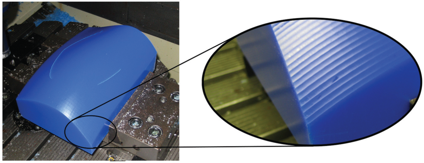
Studies in this work focused on improving the quality of the surface finish. After running some preliminary machining and measuring tests, improved methods for tool path planning between patches were developed. The tool path strategy that lifts the tool between passes and overlaps passes helped to reduce the boundary marks. Also, the constant feed rate obtained in the 3½½-axis machining tests helps to obtain a consistent surface finish. Additionally, considerations are taken into account if the last point of the pass is inside the surface, that is, when the surface is partitioned, where the tool is lifted and moved in the air to the next tool pass to reduce boundary marks between patches. Small marks in the surface were generated between the patches boundaries, as can be seen on the surface in the inset of Figure 7. The machined surface had a good surface finish, although the boundaries could be easily identified because of different feed directions used for each patch. Tests conducted with CMM machines verified that the unevenness was still within tolerance.
RBM 3½½-axis machining strategy versus the 5-axis machining RBM
The implementation of 3½½-axis machining with the RBM for tool positioning is compared to the traditional 5-axis RBM machining. The comparative experiment consisted of machining the two surfaces described above employing both methods: the extension of the RBM for 3½½-axis and the 5-axis RBM; afterward, the time expended manufacturing each surface is compared. Both experiments were conducted under the same machining conditions: feed speed, indexing speed, and tooling. Table 3 shows the machining time required for manufacturing each surface. The table also demonstrates the smaller time expended with the RBM 3½½-axis for machining one surface as compared to the time expended for manufacturing the same surfaces when employing the 5-axis RBM. For both surfaces, the proposed strategy achieved a machining time of about 17% lower than 5-axis RBM (the machining time for Surface 2 using the 5-axis RBM was estimated because the tool orientations required to machine it were off the limits of the machine). The estimated time was determined by extrapolating the time obtained to machine 80% of the surface.
Experimental machining times (min).
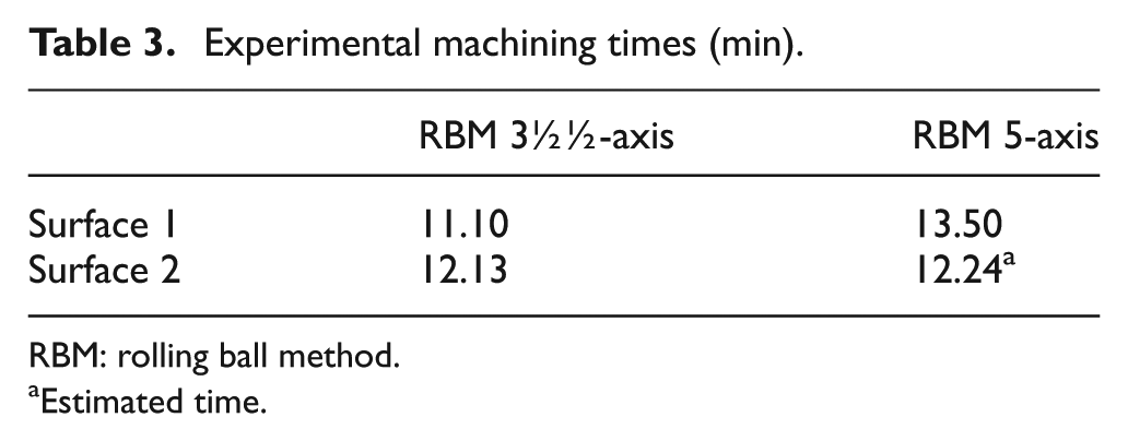
RBM: rolling ball method.
Estimated time.
Based on the results obtained on the machining tests, it can be concluded that the RBM is a useful tool to identify the adjacent sections of a surface where a large radius of the tool could be applied to maximize the removal of material per pass and thus minimize the machining time. It can also be concluded that the surfaces with low curvature or convex surfaces should be machined as a single patch, where larger tool diameters of the cutting tool can be used to match the shape of the surface. For example, the rolling ball radius calculated for Surface 2 and shown in Figure 8 indicates that the machining section largely comprises a region with a negative radius (convex sections) and concave points with a large radius (for visualization purposes, all the radii larger than 500 are plotted using the same dark red color). In this case, the minimum radius of the surface (top left corner) can be used as the limit to determine the maximum allowable effective tool radius to machine the whole surface.

Calculated rolling ball radius for Surface 2 shows both negative (convex) and positive (concave) radii (figure units are mm).
RBM applied to machining strategies
The results obtained on the machining tests presented in this work demonstrate the validity of the proposed method. Considering that the partitioning of surfaces is frequently conducted subjectively by the operator, this methodology provides guidelines to support identifying machining parameters such as the tool orientation for a particular region, surface patches that share similar geometric properties, and maximum allowable radius of the tool for adjacent points that can help reduce the machining times without interfering with the required tolerances. Therefore, the 3½½-axis machining method can be used as a guide for the computer numerical control (CNC) operator through the process of generating tool path trajectories for machining complex surfaces.
Additional to the machining tests conducted on parametric surfaces based on Bézier curves, the experiments were conducted on two other types of models to show the robustness of the proposed method. These supplementary tests are conducted using common methods in the industry to generate models using computer-aided design (CAD) systems. A third model, Surface 3 shown in Figure 9(a), is defined using an algebraic equation (19), where x runs from 0 to 100 and y runs from 0 to 40. For this case, a grid of surface points and surface normal was calculated using the equation. For each point, a rolling ball radius was calculated and used in conjunction with the surface points to run partitioning tests. Based on the methodology, the optimal partitioning proposed for this surface is the two-patch subdivision shown in Figure 9(b)


Surface 3 was generated from an algebraic equation having concave and convex surfaces, and it was adequately partitioned with the RBM: (a) simulated algebraic surface and (b) RBM partitioning (subfigure b units are mm).
The RBM can also be useful toward understanding the geometric properties of the surface. For example, the tests conducted on Surface 3 (Figure 9) show that the red patch (Patch 1) with larger curvature has larger radius on each point compared with the other patch (Figure 9). In this case, the minimum radius in Patch 1 is almost the double compared with the minimum radius of Patch 2. Calculating the minimum radius for each patch allows the operator to identify the maximum effective radius that can be used to machine the patch without gouging the surface, while still allowing to improve the efficiency of the process.
Considering that the most significant quantity of parts machined in industry are generated using commercial CAD packages, a final simulation was conducted on a complex surface modeled in such a CAD package (SolidWorks) and shown in Figure 10. It was exported using the STereoLithography (STL) file format (Figure 10(a)) and partitioned using the proposed RBM (Figure 10(b)). The STL format conveniently already provides the unit normal vectors of each triangulated area as required by the RBM.
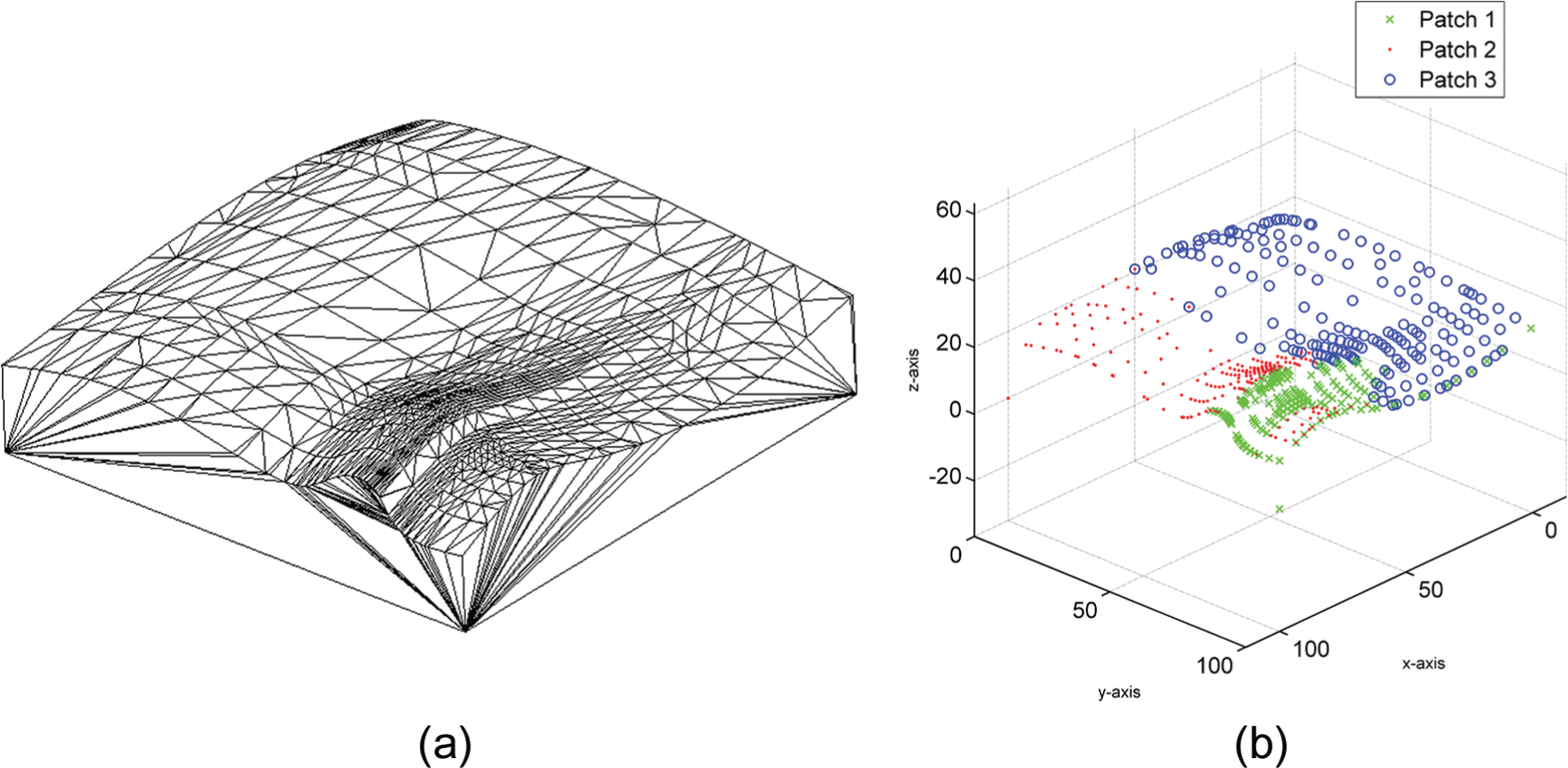
Surface 4 was generated and converted into STL format having significant concave and convex surfaces, and it was adequately partitioned with the RBM: (a) CAD-based STL surface and (b) RBM partitioning (subfigure b units are mm).
It is important to note that the CNC operator must take some considerations during tool path generation where disjointed patches may occur and the tool may be forced to be lifted up and down during machining depending on the feed direction. Nevertheless, Figure 10 shows the results obtained for Surface 4 validating that the method correctly partitions regions that share similar geometric properties.
Conclusion
The work presented in this article demonstrated that 3½½-axis machining can be an efficient and practical alternative for surface machining. The 3½½-axis machining not only offers a reduced capital investment and operator training but also produces machining times comparable with 5-axis machining methods.
The implementation of the 3½½-axis machining with the RBM provides improvements in surface partitioning and tool positioning. The proposed method was first tested on two Bézier surfaces and compared to the 5-axis method implemented with the RBM for tool positioning. The two test surfaces were machined using an adequate partitioning that leads to shorter machining time. For both test surfaces, the machining time was shorter using the proposed strategy than using 5-axis method implemented with the RBM. Two additional surfaces, one algebraic based and the other triangulation based, were simulated to demonstrate the novel surface partitioning capabilities of the RBM.
Although the machining conditions for the 3½½-axis machining and 5-axis machining were the same, 3½½-axis machining operations can be optimized with the use of higher machining feed rates. Because the tool axis remains fixed during cutting, the tool can offer a better surface finish and constant feed rates. Moreover, the tool supports higher feed rates that can result in further improvements, but discussions about speed are beyond the scope of this work. 6 Certainly, this work has demonstrated that 3½½-axis machining can provide a competitive solution to complex surface machining, a solution that is comparable in quality and performance to the higher cost 5-axis machines.
Footnotes
Academic Editor: Duc T Pham
Declaration of conflicting interests
The author(s) declared no potential conflicts of interest with respect to the research, authorship, and/or publication of this article.
Funding
The author(s) disclosed receipt of the following financial support for the research, authorship, and/or publication of this article: Partial financial support was from grants of NSERC, CONACYT, CFI, and OIT. Further support for this work came from the Tecnologico de Monterrey (ITESM), Center for Robotics and Intelligent Systems (CRIS), Laboratorio de Robotica del Area Noreste y Centro de Mexico, the E-Robots Research Group located in Eugenio Garza Sada 2501, Monterrey, Nuevo Leon, Mexico and the Fablab Chihuahua, in Chihuahua, Mexico.