
Abstract
Blisk is a difficult processing part with complex structure. The polishing quality and accuracy of the blade surface will significantly affect its performance and life. A new abrasive belt system is developed to grind and polish the blade on the blisk. In view of the problem that the abrasive belt is easy to interfere with the adjacent blades in the grinding and polishing process, an algorithm for judging the critical interference state is proposed based on the structural characteristics of the abrasive belt tool system and the actual grinding and polishing process of the blades. On the basis of above, a new algorithm is developed to calculate the range of interference-free wrap angle of the abrasive belt tool system. This paper established a simulation model based on VERICUT software and simulated the process of the blisk polishing. The simulation and experiment results verifies the effectiveness of the algorithm.
Introduction
As the core part of the aircraft and the source power to promote the development of aerospace industry, the aerospace engine has a direct impact on the performance of the aircraft. A comprehensive performance index of aeroengine is the ratio of the engine thrust to the engine weight, known as the thrust-weight ratio. At present, the integral blisk structure in the turbine compressor can greatly improve the thrust-weight ratio and the reliability of the aeroengine. 1 The blisk is composed of the blade and the wheel disc, which reduces the weight by about 50% and avoids the loss of airflow in the gap of the connecting parts. However, the structure of the blisk is complex and the manufacturing process is difficult. The technology of precision forming of the blisk mainly includes CNC milling,2,3 electrochemical machining (ECM),4,5 and electrical discharge machining (EDM). 6 After the forming of the blisk, the surface quality of the blade on the blisk is poor, which still cannot meet the manufacturing accuracy requirements of the blisk.
Traditionally, the blade surface finishing technology relies mainly on manual polishing process. The efficiency of manual polishing is very low and the workload is very high. The quality of products depends on the skill, experience, and operation proficiency of the workers. In addition, manual polishing is easy to cause damage to the blade surface, and the quality of the polished surface cannot be guaranteed, which will reduces the reliability of the blisk. 7
The polishing methods of the blade mainly include the grinding wheel polishing and the abrasive belt polishing. The grinding wheel polishing is mainly applicable to the simple blade profile, while for the complex blade profile like blisk, the abrasive belt polishing is more suitable. In addition, compared with the grinding wheel polishing, the abrasive belt polishing has advantages of the fast heat dissipation, good surface quality and high grinding efficiency, 8 thus it is widely used in polishing blade. Zhang et al. 9 studied the contact between the contact wheel and the curved surface in the polishing process and used Signorini contact model to model the contact of the abrasive belt polishing. Considering the complicated contact between the contact wheel and the workpiece, Wang and Yun 10 proposed a new polishing path planning method for the belt polishing process by optimizing the curve interval to generate more cutter locations at the local surface with large curvature and less cutter locations at the local surface with small curvature. In order to ensure a stable polishing effect, it is necessary to control the normal polishing force of the abrasive belt during polishing. Wang and Sun 11 propose a method which uses interference-free tool paths to predict and compensate for deformation error during the spiral milling of blades. A finite element simulation of the blisk blade milling process was conducted using an interference-free spiral milling NC machining tool path based on the curvature attribute of the blade twisted surface. Wei et al. 12 proposed a non-interference cone area detection method. For the global interference that may occur between the handle of the polishing grinding head and the adjacent blades, an angle range can be planned in advance, and the axial orientation of the grinding head will not occur within this range.
The configuration of the blisk is complex, and a common belt tool system is easy to produce the interference between the cutter and the blade. Zhao et al. 13 and Chen et al.14,15used a method of “five axis numerical control + flexible grinding head + elastic abrasive (emery cloth wheel)” to carry out the self-adaptive polishing of the blisk, and studied the trajectory planning and the process parameter optimization. This method can effectively avoid the phenomena of “over-polishing” and “lacking-polishing.” But the small elastic grinding head is particularly prone to abrade and lead to poor polishing effect. The abrasive belt is less easy to abrade, because it is a long strip and there are many abrasive grains participating in polishing process. Li et al. 16 and Xiao and Huang 17 used the belt grinding technology to polish the blisk on a seven-six axis CNC machine tool. Based on the analysis of the grinding technology of the blade tip, profile, edge, and runner surface of the blisk, a kind of the abrasive belt grinding machine and the tool system suitable for the inner and outer surface of the blisk was developed. They also analyzed the optimization of the process parameters and the polishing trajectory planning. The main problem is that the abrasive belt is easy to interfere with the blades during the polishing process because of the small gap between the adjacent blades. At present, few studies have been reported on the interference problems of the abrasive belt polishing. 18
When the abrasive belt polishing tool system is polishing a blade, the suspended belt on both sides of the contact wheel is likely to interfere with the polished blade and the corresponding adjacent blade. This paper proposed a new algorithm to calculated the range of the interference-free angle of the abrasive belt in the contact wheel. The remainder of the paper is organized as follows. Section 2 introduced a new developed grinding and polishing system of the blisk. Section 3 presented a new algorithm to judge the critical interference state of the abrasive belt. Section 4 established a simulation model based on VERICUT and simulated the process of the blisk polishing, which verified the effectiveness of the proposed algorithm. Conclusions are presented in Section 5.
Abrasive belt grinding system of blisk
As shown in Figure 1(a) and (b), the research target of this paper is the open blisk. The sample of the blisk is made of stainless steel. The diameter of the blisk in Figure 1 is 466 mm and the thickness is 40 mm. A total of 34 blades are arranged around the wheel. The blade surface is free-form surface. As shown in Figure 1(c) and (d), a blade mainly includes the basin surface (concavity), the back surface (convexity), the inlet edge, the exhaust edge, and the blade root. This paper mainly studies the polishing of the concave and convex blade.

Blisk model. (a) Model of the integral blisk. (b) Real integral blisk. (c) Concavity (basin surface) model. (d) Convexity (back surface) model.
According to the requirements of the polishing and measuring process, a CNC machine tool with seven-five axis was developed as shown in Figure 2. The machine tool is a vertical CNC machine with double columns, which can be divided into the polishing side and the measuring side. It can be used to polish and measure a workpiece at one time, so as to realize in-place measurement of the blisk and avoid repeated clamping error of the workpiece.

A polishing and measuring CNC machine tool with seven-five axis.
The abrasive belt polishing tool system is shown in Figure 3. Due to the close distance between adjacent blades, the abrasive belt may interfere with blades during polishing process, thus it is necessary to determine the range of the interference-free wrap angle for two contact wheels.
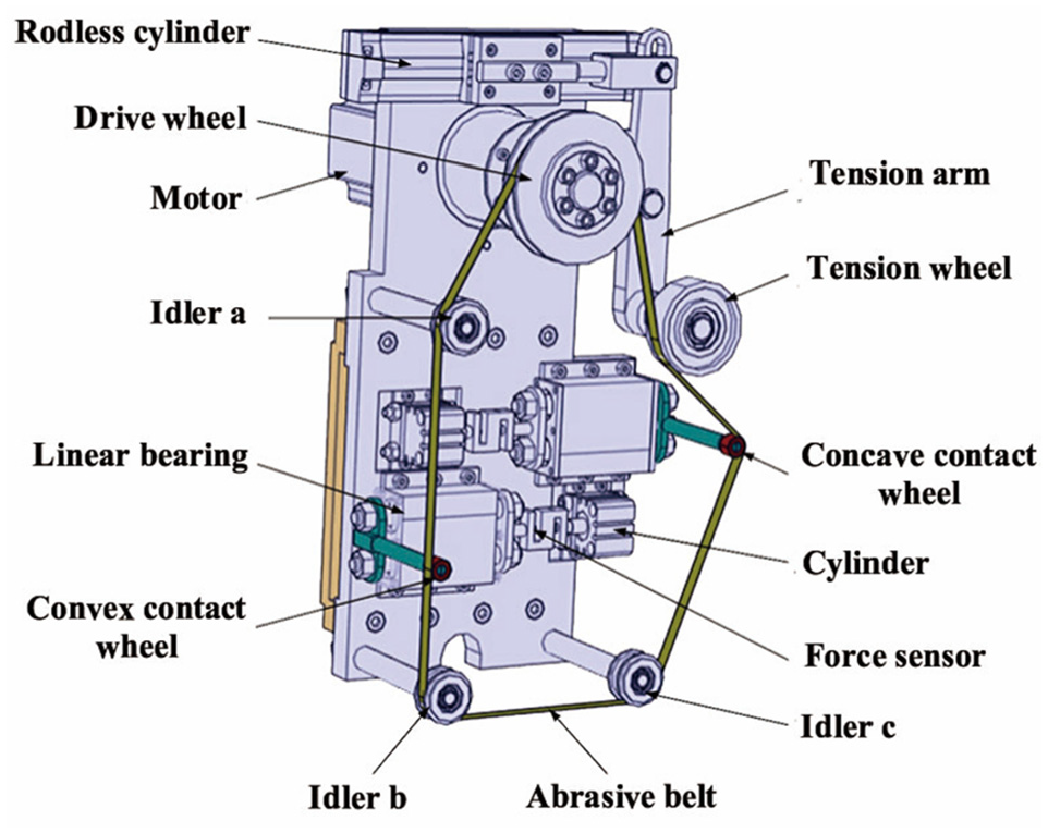
Structure of abrasive belt polishing tool system.
Interference analysis of the abrasive belt polishing
Interference problems of the abrasive belt polishing
Figure 4(a) shows the polishing state of the concave blade. When the abrasive belt is polishing a blade surface, the suspended belt on both sides of the contact wheel is likely to interfere with the polished blade and the adjacent blades. The abrasive belt supported by concave contact wheel is divided into S1 and S2 sections with the boundary of polishing point. According to the analysis, there may be four kinds of interference, such as the interference between the abrasive belt in S1 section and the exhaust edge of the polished blade, the interference between the abrasive belt in S1 section and the exhaust edge of adjacent blade 1, the interference between the abrasive belt in S2 section and the inlet edge, and the interference between the abrasive belt in S2 section and the inlet edge of adjacent blade 1.

Polishing state of the concave and convex blade. (a) Polishing state of the concave blade. (b) Polishing state of the convex blade.
Figure 4(b) shows the polishing state of the convex blade. The abrasive belt supported by convex contact wheel is divided into S3 and S4 sections with the boundary of polishing point. According to the analysis, the abrasive belt will not interfere with the polished blade itself when polishing the convexity. There are only two kinds of interference, which are the interference between the abrasive belt in S3 section and the exhaust edge of adjacent blade 2, and the interference between the abrasive belt in S4 section and the inlet edge of adjacent blade 2.
Figure 5 is a simplified two-dimensional plan of the abrasive belt polishing tool system. Let the angle between the abrasive belt in S1 section and the concave virtual axis Na be α, and let the angle between S2 section and the concave virtual axis Na be β. Let the angle between the abrasive belt in S3 section and the convex virtual axis Nt be γ, and let the angle between the abrasive belt in S4 segment and convex virtual axis Nt be δ. In order to prevent the interference of belt in the process of polishing, it is necessary to calculate the range of the interference-free angle of α, β, γ, and δ. Then the interference-free angle of the belt on the both sides of the contact wheel is selected within the range of the interference-free angle, which is an important basis for the structural design of the belt polishing system.

Simplified plan of abrasive belt polishing system.
Calculation of interference-free angle
Analysis of interference-free angle
The selection of the points needs to be adjusted according to the actual situation, including the size of the blades and the spacing between points. X polished points are respectively extracted from the seven sections of the concavity and convexity of the blade theoretical model, which are recorded as M, and the corresponding normal vector is recorded as Nm. The center point of the contact wheel should coincide with the cutter point when polishing the blade, and the vector of virtual cutter axis should be parallel to the spatial normal vector of each polished point. The point M′ is rotated from the polished point M through C axis during the actual polishing process. The normal vector after rotation is recorded as Nm′. The point M and the point M′ are the same point on the blade with different coordinate. Because the plane of concave virtual cutter vector Na and convex virtual cutter vector Nt is parallel to the XOZ plane of the machine coordinate system, the normal vector Nm′ corresponding to the polished point M′ is also parallel to the XOZ plane after rotation. The interference-free angle of α, β, γ, and δ can be converted into the interference-free angles between the abrasive belt S1, S2, S3, S4, S5, S6, and the vector Nm′. When the belt tool are polishing at the point M′ on the blade surface, the section drawing is shown in Figure 6.

Plan of polishing interference judgment.
The center point of the contact wheel is point O, the radius of the contact wheel is r (r = 7 mm), and the thickness of the abrasive belt is h = 0.5 mm. Line L1, L2, L3, and L4 are four interference boundaries of the concavity. L1 and L4 are the critical interference boundaries between the abrasive belt and the polished blade when polishing at the point M′. L2 and L3 are the critical interference boundaries between the abrasive belt and the adjacent blade 1 when polishing at the point M′. L5 and L6 are the critical interference boundaries between the abrasive belt and the adjacent blade 2 when polishing at the point M′ on then convex surface. When polishing at the point M, point Am′, Bm′, Cm′, Dm′, Em′, and Fm′ are the extreme points of Z coordinate in the range of the abrasive belt where the inlet and exhaust edge points are concentrated. The calculation method will be introduced detailedly in the following section. The angles between the critical interference lines L1, L2, L3, L4, L5, L6 and the virtual cutter vector are α1, α2, β1, β2, γ1, and δ1, respectively. In order to ensure that the abrasive belt does not interfere with the blade, the abrasive belt in S1 section should be between the critical interference line L1 and L2, and the abrasive belt in S2 section should be between the critical interference line L3 and L4 when polishing the concavity of the blade. Therefore, when polishing at the point M of the concavity, the interference-free condition of the belt polishing system is

When polishing the convexity, the abrasive belt in S3 section shall not exceed the critical interference line L5, and the belt in S2 section shall not exceed the critical interference line L6. Therefore, when polishing at the point M of the convexity, the interference-free condition of the belt polishing system is

Extract data points of the inlet and exhaust edge
In the blisk model, data points are extracted from the inlet and exhaust edge of the polished blade, adjacent blade 1 and adjacent blade 2, as shown in Figure 7. The workpiece coordinate system is recorded as OXYZ. Y points are extracted by the equal arc length method on the exhaust edge of the polished blade, which are recorded as the point set Ai. By using the same method, the points on the exhaust edge of adjacent blade 1 are extracted as Bi, Ci, Di, Ei, Fi.

Schematic diagram of data point extraction for the theoretical model of blade.
Coordinate transformation of polished points and data points of the inlet and exhaust edge
In order to ensure that the abrasive belt polishing tool system is parallel to the space normal vector of the point M, C axis of the machine tool needs to turn an angle when polishing at the point M. Since the polishing side of the machine tool is a five-axis CNC system with swing turntable structure, the Y-axis component of the normal vector Nm′(lm′, mm′, nm′) at the point M′ after rotation is zero. Let the rotation angle of C axis be θm.
For machine tool, the rotation transformation formula with the rotation angle θ around the Z axis is given by

Then the rotation formula is Nm′ = Rot(z, θm)·Nm, which gives

And the solution of the equation is given by

Let mm′ = 0. When polishing at the point M, the angle that the C axis needs to rotate can be expressed as

Then, after the point M rotates around the C axis, the calculation formula of the point M′ is M′ = Rot(z, θm)·M, which gives

Finally, the formula for calculating the coordinate of the point M′ is

When calculating the interference-free angle of the point M, the point set of the polished blade, adjacent blade 1, adjacent blade 2, inlet edge, and exhaust edge must also turn the same angle. By using the same calculation method, we can calculate the coordinate transformation formulas of point set Ai′, Bi′, Ci′, Di′, Ei′, and Fi′. The formulas are shown in Table 1.
Coordinate transformation formulas of point set of the inlet and exhaust edge.

Selection of extreme points on the inlet and exhaust edge
When calculating the interference-free angle of the point M′ after rotation, we need to select the extreme points of the inlet and exhaust edge of the polished blade and the adjacent blade corresponding to the point M′, which are recorded as Am′, Bm′, Cm′, Dm′, Em′, and Fm′, from the point sets of the inlet and exhaust edge of the blade after coordinate transformation, which are Ai′, Bi′, Ci′, Di′, Ei′, and Fi′. The width of the belt should be considered in the calculation of interference-free wrap angle. Taking the selection of the extreme point Bm′ from the exhaust edge of adjacent blade 1 as an example, we will introduce a method of selecting extreme points of the polished blades and adjacent blades. When polishing at the point M′, the point with the largest Z coordinate value in the point set Bi′ first interferes with the belt. Therefore, the point with the maximum Z coordinate value in the point set Bi′ is selected as the extreme point Bm′, as shown in Figure 8.
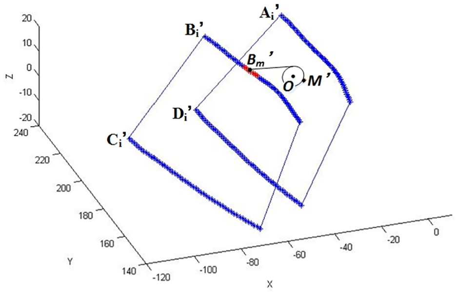
Schematic diagram about extreme point selection of the exhaust edge of adjacent blade 1.
According to the same method, we can calculate the extreme points Am′, Cm′, Dm′, Em′, and Fm′ of the inlet and exhaust edge of the polished blade, adjacent blade 1, and adjacent blade 2.
Solution of interference-free angle
As shown in Figure 9, the critical interference-free angles of the belt can be calculated by the mathematical algorithms. The concentric circle in the figure is a simplified diagram of the contact wheel and the belt. In XOZ coordinate system, taking the calculation process of α2 as an example, this paper introduces a calculation method of critical interference-free angle of abrasive belt. In XOZ coordinate system, the coordinate of point M′ is (xm′, zm′) and the coordinate of the normal vector Nm′ is (lm′, nm′). The contact wheel radius Rj = 7 mm and the belt thickness h = 0.5 mm. The formula for the coordinate of center point O on the contact wheel can be expressed as


Calculation schematic diagram of critical interference-free angles. (a) Calculation schematic diagram of critical interference-free angles α1, α2, and γ1. (b) Calculation schematic diagram of critical interference-free angles β1, β2, and δ1.
Let the vector from point O to extreme point Bm′ on the exhaust edge of adjacent blade be

Let the angle between the vector

Let the angle between the vector

The critical angle α2 can be expressed as

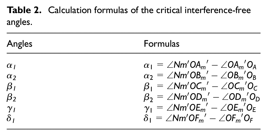
Using the same method described above, we can calculate the remaining critical interference-free angles α1, α2, β1, β2, γ1, and δ1, and summarize the calculation formulas in Table 2.
Calculation formulas of the critical interference-free angles.
Simulation and experiment
Analysis of calculation results
The blade of blisk is free-form surface. When calculating the interference-free angles of the concave belt, take seven section lines with coordinates of y = 170, y = 180, y = 190, y = 200, y = 210, y = 220, and y = 230 and take 100 polished points on each section line. First calculate the interference-free angles of 100 polished points on each section line separately and then take the intersection as interference-free angles of this section line. Finally, take the intersection of the calculation results from each section line as interference-free angles of the polished blade. The results are shown in Figure 10. The points in areas A, B, C, D, E, and F are extreme points on the inlet and exhaust edge of the polished blade and the adjacent blade, which are corresponding to different polished points. The straight lines are the critical interference lines corresponding to different polished points, and the concentric circles are simplified diagrams of the contact wheel and the abrasive belt.

Calculation results of critical interference-free angle. (a) Interference-free angle of y = 170 on concavity. (b) Interference-free angle of y = 170 on convexity. (c) Interference-free angle of y = 180 on concavity. (d) Interference-free angle of y = 180 on convexity. (e) Interference-free angle of y = 190 on concavity. (f) Interference-free angle of y = 190 on convexity. (g) Interference-free angle of y = 200 on concavity. (h) Interference-free angle of y = 200 on convexity. (i) Interference-free angle of y = 210 on concavity. (j) Interference-free angle of y = 210 on convexity. (k) Interference-free angle of y = 220 on concavity. (l) Interference-free angle of y = 220 on convexity. (m) Interference-free angle of y = 230 on concavity. (n) Interference-free angle of y = 230 on convexity.
It can be seen from the result diagrams that the interference-free angles of each polished point changes gradually, which can preliminarily verify the correctness of the program and algorithm. At the same time, in the calculation process, the critical values of interference-free angle corresponding to the polished points of each section line may not be the starting and ending polished points of the section line. Similarly, the critical values of interference-free angle corresponding to seven section lines are not necessarily the head and tail section line. Therefore, it is more accurate to calculate the interference-free angle by calculating the interference-free angles of all polished points on seven sections.
The calculation results of the critical interference-free angles are summarized in Table 3. When polishing the section line y = 230 on the concavity, there is no interference between the belt and the inlet edge of the adjacent blade 1, so the angle β1 in the table has no value. After obtaining the critical interference-free angles of seven section lines, α1 and β2 are taken as the maximum critical interference-free angle in each section line, and α2, β1, γ1, and δ1 are taken as the minimum critical interference-free angle in each section.
Critical inteference-free angle of the abrasive belt polishing.

It can be seen from the table that the range of the interference-free angle of the concave belt is 28.23° < α < 76.82° and 68.64° < β < 69.28°. The range of the interference-free angle of the convex belt is 89.60° < γ < 90° and 68.08° < δ < 90°.
Simulation by VERICUT and experimental verification
The polishing process of the concavity and convexity of the blisk is simulated respectively, as shown in Figure 11. In the simulation part view, the contact area between the simplified polishing cutter model and the workpiece will be displayed in red. During the entire grinding and polishing process, the grinding and polishing trajectory is consistent with the planned trajectory, and the CNC program is error-free. The belt did not interfere with the polished blades and the adjacent blades, and further verified the calculation results of the interference-free angle of the belts described in Section 3. The actual polishing process also verified the correctness of the simulation, as shown in Figure 12.
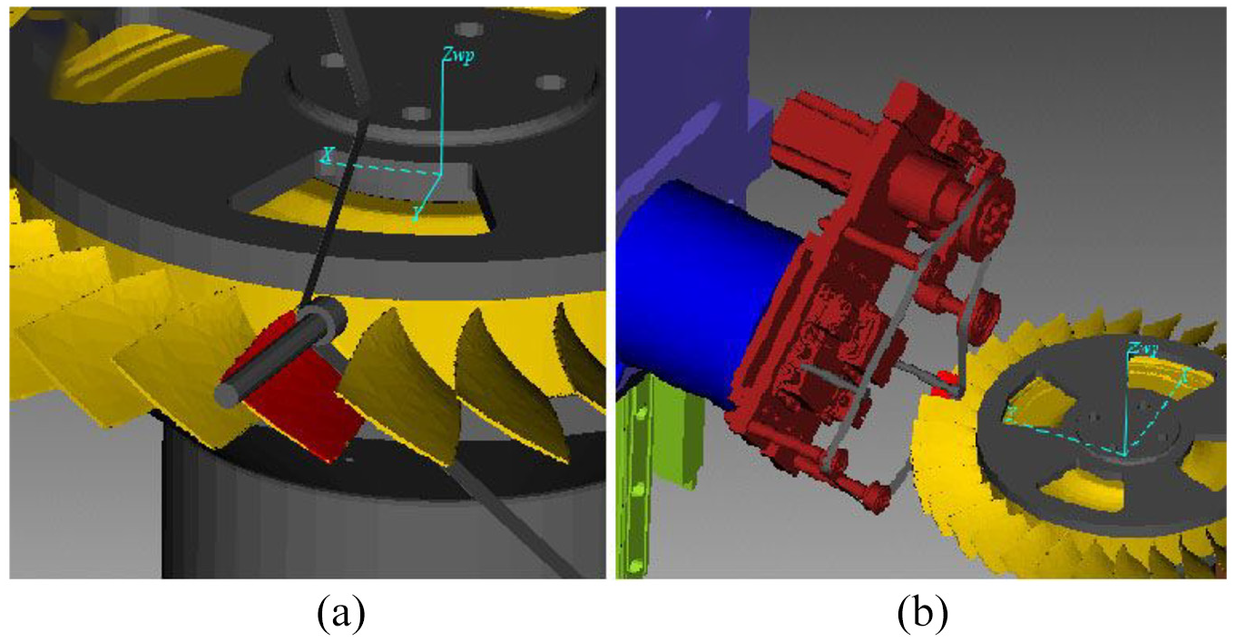
Numerical control simulation of grinding and polishing of blisk. (a) View of workpiece. (b) View of machine tool.

Diagram of actual polishing process. (a) Interference checking for the concave blade surface. (b) Interference checking for the convex blade surface.
After polishing, the roughness of the blade surface is required to reach Ra 0.4 μm and the surface accuracy is required to be controlled between −70 μm ∼+80 μm. The measurement results of surface roughness are shown in Table 4 and the measurement results of surface precision are shown in Table 5. The picture of the comparison before and after polishing is shown in Figure 13.
Surface roughness of blisk.

Surface accuracy of the blisk.


Comparison before and after polishing.
Conclusion
In this paper, a new abrasive belt tool and a new type of seven-five axis CNC machine tool is developed for the grinding and polishing of the blisk. The abrasive belt is likely to interference with the blisk in the blade polishing process. According to the structure of the abrasive belt tool and the condition of the abrasive belt in the actual blade polishing process, this paper proposed an algorithm to judge the interference and calculate the interference-free wrap angle of the abrasive belt in the contact wheel. In the algorithm, the calculation process is transformed into the XOZ plane through coordinate transformation, which simplifies the solving process. For the blisk and the proposed belt tool in this paper, the range of interference-free angles of concave belt are 28.23° < α < 76.82° and 68.64° < β < 69.28°, and the range of interference-free angles of convex belt are 89.60° < γ < 90° and 68.08° < δ < 90°. The effectiveness of the algorithm is proved by the VERICUT simulation and the polishing experiment.
Footnotes
Handling Editor: James Baldwin
Declaration of conflicting interests
The author(s) declared no potential conflicts of interest with respect to the research, authorship, and/or publication of this article.
Funding
The author(s) disclosed receipt of the following financial support for the research, authorship, and/or publication of this article: The authors would like to express their sincere thanks for the financial support from the National Natural Science Foundation of China [Grant No. 51975392], the Natural Science Foundation of the Jiangsu Higher Education Institutions of China [Grant No. 19KJA220001], and the Postdoctoral Science Foundation of China [Grant No. 2015M571800].