
Abstract
Blisk, as the key component in the aero-engine, is hard to be fabricated for the complexity geometry in comparison with separable impeller. In the process, cutter interference is easy to occur because of the narrow groove between adjacent blades. To solve this problem, the paper proposed a dynamic adjustment method for the cutter, through which a cutter interference can be avoided dynamically realized when the cutter approach to the potential interference zone and a smooth transition between two adjacent cutter traces can be realized instantly. Finally, with the proposed method, a polish experiment is conducted, showing its effectiveness in improving the precise and reducing the roughness.
Introduction
Blisk is an important part of the aero-engine, of which the precision plays an important role in the overall performance of the engine and its operation efficiency (shown in Figure 1). In order to make its surface smooth, belt polish-grinding processing is often used for its finishing. Nowadays, the traditional manual polish-grinding process is replaced by the automotive processing in a machine tool; many works have focused on it.1–8

Blisk.
Feldmann et al. 9 proposed a flexible grinding scheme suiting for the structural features of the blisk based on the manual processing. Ren et al. 10 proposed a four-axis vector control method based on the tool axis control line for the interference problem in the grinding process and also proposed a five-coordinate branch axis processing method. 11 Zhu et al. 12 studied the trajectory planning and programming techniques of the blisk based on five-axis computer numerical control (CNC) polishing machine. Duan et al. 13 used the six-axis CNC abrasive belt grinder to polish the open integral blade, and they get a leaf shape with a high surface quality.
The above literatures show that most scholars in this field focus on improving the processing quality and machining efficiency of the blisk surface, while the tool axis interference avoiding method has not paid attention to. In processing, tool interference is occurred when the tool handle contacts with workpiece. For the processing of blisk, this interference is hard to be avoided since the groove between two blades is always narrow.
Focused on this, the paper proposed a dynamic tool adjustment method based on the geometry of adjacent blades. In this method, tool interference is avoided by adjusting the cutter swing angle. The principle and mathematical models of the proposed method are all discussed. Finally, a cutting experiment is conducted, showing the availability of the method in tool axis avoidance. 14
Grinding machine structure and tool analyzes
Blisk special grinding machine basic structure
In this article, 13 aix CNC abrasive belt grinding machine with symmetrical double polished tool is used to fulfill the structure of the blisk. Since V-axis is common used for either symmetrical part, each part contains seven-linkage machine axis, which is configured with three linear axes and three rotating axes as shown in Figure 2. Three linear axes are used for the position control, and three rotating axes are used for orientation control, so that the grinding wheel can be kept contact with blade surface, contact normals can be kept following the surface normals, and the contact force can be controlled through surface remains, the X-axis, Y-axis, Z-axis moves relative to the machine bed.15–17

Blisk machine structure.
Flexible grinding tools
Since the gap between the blisk blades is narrow, in order to minimize the interference of the polishing tool, a new type of grinding head is designed as shown in Figure 3, and the polish is realized by the outer side of the grinding wheel. With this grinding head, the tool interference can be reduced and the polishing efficiency is relatively improved; the wheel side polish can avoid the surface overcast or ablative defects caused by excessive pressure in the processing. Besides, pressure sensors are also added to the floating pressure device to realize real-time the monitoring and control of floating pressure.18,19

Flexible polishing tool.
The polish device is composed of fresh belt wheel, transit wheel, tension wheel, floating pressure mechanism, support rod fixing mechanism, grinding belt tightening device, and so on: (a) the polishing tool abrasive belt can be updated in real time, which is achieved by combining the belt wheel with the tension wheel. (b) The main function of the tension roller is inverting the abrasive belt and increasing the contact wheel so that the sliding phenomenon in the polishing process can be effectively reduced. (c) Floating pressure mechanism is composed of two spring components, which can help the contact wheel float toward the right and left sides to ensure the grinder contact with the convex and concave sides of the blades.
The method of dynamic adjustment of the grinding tool
Main curvature of blade surface
In order to obtain the best contact performance between the contact wheel and the blade, and improve the machining efficiency of the work piece, it is important to ensure that the axial direction of the contact wheel along the direction of the limited principal curvature of the contact point (Figure 4). In reference of the main curvature

where the blade surface is defined by parameters u and v, namely
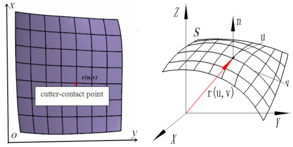
Blade parametric surface.
Thus, the main curvature direction at contact point can be obtained by the following equations
where the unite normal vector of the surface can be

Principle for the control of tool axis
The polishing tool path is u-parameter-curve of v-parameter-curve. The contact point between the cutter and blade is discretized by the path curve based on the machining accuracy. As shown in Figure 5, the position the cutter center is calculated by the contact normal vector.
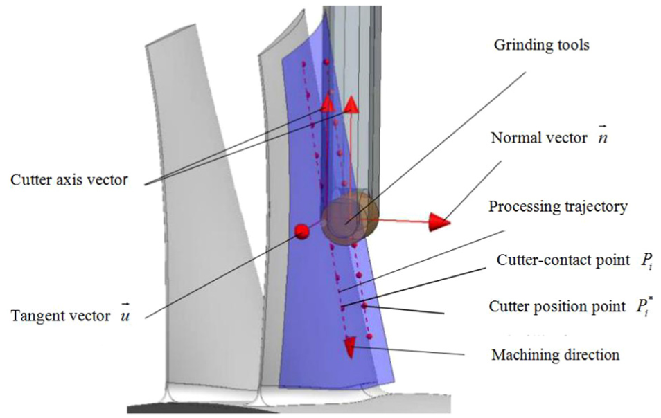
Relationship between normal vector and tangential vector at polishing tool.

where n is the unit normal vector of cutter contact point

Relationship between cutter contact
In order to avoid the cutter interference, a dynamic adjustment of the angle
The optimized cutter swing angle
Based on the above discussion, for dynamical cutter adaption, the optimized cutter swing angle can be solved based on limitation of tool swing angle θi. The detailed solving processing is as follows:
1. Based on the machining precision and machining quality of blade profile, the equal parameter method is used to make the machining trajectories and equidistant discrete knife contacts, and offset surface of two adjacent blade surfaces is obtained, in which the offset distance is
2. The parameter curve and the cutter contact point are projected into the XOY plane. In order to show the processing, for example, 10 tool paths are defined as


Critical cutter axis between adjacent blades.
Then taking the derivative of the equations above, the slope of each of the cutter contact points can be obtained as shown in Figure 8, which will be used to judge the interference later.

The curvature of each point on the trajectory.
Through a simulation in the environment of VERICUT, the interference position is found closely related to the surface slope, meaning that the grinding tool interference can be judged by the slope. As shown in Figure 8, if
3. As shown in Figure 9, the current cutter position point and the cutter position point at the blade tip get two critical tool axis vectors, the critical tool axis vector can rotate angle of scope is
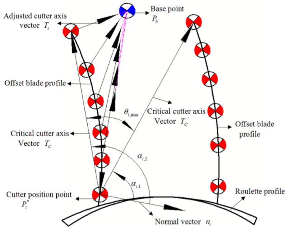
Tool axis vector
4. The optimal rotation angle

5. According to the length of tool axis d, combining the adjusted knife axis vector to get the diameter vector of the tool endpoint, and taking this point as a base point

where
6. Tool axial vector after rotation, as well as the normal and the tangent vectors for cutter contact point, is first calculated.
We can first obtain the initial position of the polishing tool at the cutter contact point. Subsequently, with the polishing tool l thrown around

If the number of discrete knife sites is N, the single parameter curve of the cutter contact is

Through analyzing the machining tool path after the offset blade profile, the first process tool path is found to be driven from top to bottom by the polishing tool; setting as point

Polishing experiment and result analysis
Blade profile polishing tool path planning
Since the blade profile is complex, the rational processing path will directly affect the quality and efficiency of the grinding process. If the machining path is divided by the proposed polishing method, it can be divided into lateral polishing and vertical polishing. Through considering the grinding quality of blade surface, this article adopts the vertical polishing method (as shown in Figure 10(a)).
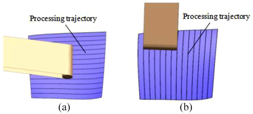
Processing trajectories: (a) longitudinal and (b) transverse.
Solution of the axis motion of machine tool
In order to realize automatic polishing, it is necessary to further understand the composition of each axis of NC abrasive belt grinder, which is based on the Y1-axis, the X1-axis, and the Z1-axis, as shown in Figure 1.
It set the tool coordinate system is

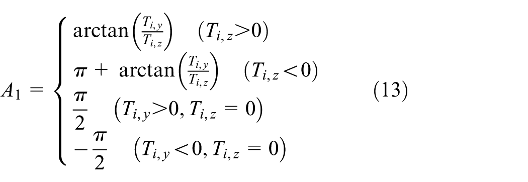
where tangential unit vector is unit Uti, and unit normal vector is unit ni. Thus, the

Finally, A1 axis can be represented as follows
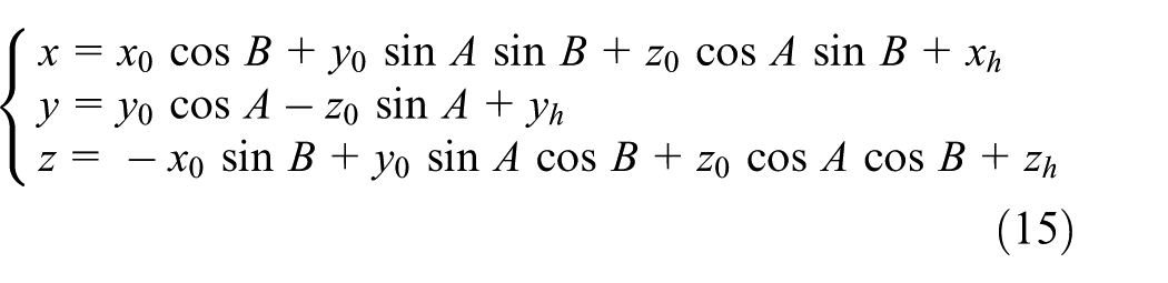
After solving three rotating axes, then we need to solve for the remaining three straight axes; thus solving three straight axis mathematical expressions is necessary. Supposed that the blade surface cutter contact point is P, according to the normal vector

R is the contact wheel radius, H is the distance between the centerline of the contact wheel and the intersection of the three axes of rotation, so the expression for the straight axes x, y, z can be represented as
Experiment analysis
Here four titanium alloy blisk specimens are used for CNC abrasive belt grinding. After polishing, the surface roughness is less than

Grinding results comparison chart: (a) blisk grinding, (b) FM surface, (c) BG surface, (d) deviation report before grinding, and (e) deviation report before grinding.
Conclusion
This article developed a new polishing machine tool, which has the function of intermittent update grinding belt and thus guarantee grinding precision in the while surface.
The paper proposed a method to dynamically adjust the position of the polishing tool to avoid tool interference, and hence proved to be feasibility and reliability by processing experiment.
In order to improve the surface quality, reasonable collocation of the polishing process parameters was used in the experiment.
Footnotes
Handling Editor: James Baldwin
Declaration of conflicting interests
The author(s) declared no potential conflicts of interest with respect to the research, authorship, and/or publication of this article.
Funding
The author(s) disclosed receipt of the following financial support for the research, authorship, and/or publication of this article: This study was supported by the Chongqing Science and Technology Bureau (cstc2018jszx-cyzdX0061).