
Abstract
Blisk is an important component for the aero-engine, whose surface quality plays a significant role in its performance. So it is necessary to develop a novel and viable method to improve the blisk leading and trailing edge profile shape precision and surface quality. In order to achieve these aims, the method of adaptive belt precision grinding is used to the precision manufacture for weak rigidity deformation of blisk leading and trailing edge in this article. First, the methodology of adaptive belt precision grinding for blade deformation and material removal precision is analyzed by the characteristics of blisk leading and trailing edge, the blade deformation errors are compensated by the detection and control of the contact pressure, and the precision grinding is achieved by controlling rotating speed of the contact wheel according to the contact between the belt and blisk leading and trailing edge. And then, the experiment of the belt grinding technology for the blisk leading and trailing edge is applied to verify this method, and at the same time, the device for adaptive belt precision grinding is illustrated. The experimental results show that for the leading and trailing edge after adaptive belt precision grinding, the surface roughness is less than 0.4 μm, the profile shape errors are less than 20%, and the surface glossy transition between the blade surface and the leading and trailing edge. It is proved that the method of adaptive belt precision grinding might be considered as a viable process for blisk precision manufacture.
Introduction
As the improvement of the aircraft aero-engine performance on bypass ratio, thrust–weight ratio and service life, the design trend of the blisk including, the structure is more complex (thin, wide chord, swept, etc.), the shape precision is higher and the materials are difficult to cutting, so the higher requirements for high efficiency and precision manufacturing technology are proposed. 1 At present, the main processing technology of blisk is linear friction welding, semi-precision milling, finishing milling, pretreatment, polishing, and shot peening. 2 However, because of the temperature and cutting force is very high between the tool and the chip or the tool and workpiece, the inconsistent serious deformation of blisk is resulted. On the other hand, due to the higher and inconsistency of material residual on the blisk surface, the position and precision of polishing is difficult to obtain. 3 Through the analysis of the failed blisk, the results show that the main reason for the failure of the blisk is the surface quality unmeet the requirements. Therefore, the blisk surface must be polished after precision milling.
Due to the complex shape, deep and narrow channel, it is difficult to use the conventional polishing method for the blisk leading and trailing edge. 4 First, the blisk surface is easily damaged by the poor accessibility of grinding tool and the blisk surface. Second, the deformation of blisk is easy to occur by the effect of higher polishing force and then the “less polished” would be resulted. Finally, the vibration is easy to occur when polishing due to the waviness of blisk surface after milling, and then the precision polishing is difficult to obtain. 5
For the characteristics of blisk, including integrated structure, complex surface, and difficult-to-cut material, the polishing technologies for blisk are studied, including the abrasive flow machining and computerized numerical control belt polishing. Gao et al. 6 established an experimental platform of abrasive flow polishing for blisk, and then the simulation and practicability are analyzed; the surface roughness is 0.14–0.45 μm. The robot grinding for the blisk is used with belt or other polishing tools by the companies, ACME, Huck, and so on. 1 Xu and Shi 7 studied the cutter path generation and interference detection applied in robot polishing based on blisk structure and analysis of blisk modeling method. Shi and colleagues8,9 designed a new air-operated flexible grinding head; at the same time, a method of adaptive sliding mode control is proposed, which is based on the extended state observer; after experimental research, the waviness and roughness of blisk are reduced nearly 50%. Lin et al. 10 researched the NC polishing path planning and programming of blade surface for open blisk. Zhang et al. 11 designed a blisk polishing device, which integrated with polishing and contact online testing, and then the positioning and clamping times are reduced; the errors caused by multiple positioning and clamping are eliminated. Xiao and colleagues12,13 presented a method to improve the profile precision and surface integrity for blisk, and in order to increase the consistency of blisk blade, which including the profile accuracy and surface integrity, the new belt grinding method is introduced.
The belt grinding for aero-engine blade leading and trailing edge is studied. Zhang et al. 14 analyzed the problems existing in polishing process for leading and trailing edges to reduce the profile errors and improve the surface quality, and the profile error is less than 0.01 mm. Zhang and Wang 15 planned the machining trajectory of grinding tool based on the structure characteristics of blade surface and grinding characteristics of belt. Tian and Song 16 adopted section method and curvature difference method to plan the robot trajectory for leading and trailing edges combining the robot and belt grinding technologies. Xiao and colleagues17,18 analyzed the grinding characteristics and process planning for the leading and trailing edge, and then the methodologies of equivalent or self-adaptive belt grinding are illustrated. And then, the methods of bob polishing and belt polishing are integrated for different regions of the compressor blade, where the leading and trailing edge is polished with belt, and after belt polishing, the profile errors of the leading and trailing edges were less than 20%.
Through the above analysis, there have no relevant reports on the polishing for blisk leading and trailing edge. So, for improving the surface integrity and profile precision of blisk, it is necessary to develop a novel and viable method to improve the blisk leading and trailing edge profile shape precision (PSP) and surface quality. In order to achieve these aims, the method of adaptive belt precision grinding (ABPG) is used to the precision manufacture for weak rigidity deformation of blisk leading and trailing edge in this article. First, the methodology of ABPG for blade deformation and material removal precision is analyzed by the characteristics of blisk leading and trailing edge, the blade deformation errors are compensated by the detection and control of the contact pressure, and the precision grinding is achieved by controlling rotating speed of the contact wheel according to the contact between the belt and blisk leading and trailing edge. And then, the experiment of the belt grinding technology for the blisk leading and trailing edge is applied to verify this method
ABPG for blisk leading and trailing edge
Adaptive control for blade deformation
Because of the weak rigidity for blisk blade, the blisk blade deformation especially for the leading and trailing edge would be appeared from the manufacture, the inner stress, and other external force, as shown in Figure 1(a).

Comparison the different methods for the leading and trailing edge: (a) deformation of the blisk blade, (b) machine for blade edge, (c) edge allowance, and (d) result analysis.
As shown in Xiao and Huang, 12 the method of constant-load adaptive belt polishing (CABP) is used to adaptive the deformation of blade under the larger grinding force, but it is difficult to realize the precision grinding for different allowance of blade, especially for the weak rigidity deformation of blisk leading and trailing edge. So the method of ABPG is proposed in this article. At the same time, because of the excessive grinding, the blade would have the second deformation with the bigger force. The traditional method polished the blade with the theoretical trajectory, the excessive grinding would be happened in upper blade face, and the above blade surface would not be polished, as shown in Figure 1(b). And the method of ABPG is to compensate the blade deformation, so the dimensional precision would be guaranteed. At the same time, the precision would be realized, because of the unequal allowance of the blade edge, as shown in Figure 1(c). When the deformation of blisk leading and trailing edge is recovered, the previous method would have larger errors for deformation compared with the ABPG, and the profile precision errors and closed angle have happened in traditional method, as shown in Figure 1(d).
ABPG principle for the blisk leading and trailing edge manufacture is shown in Figure 2(a). The blisk blade is polished with the parameters of constant-load F, the belt speed Vs, and so on. Micro-displacement movement is controlled by the accurate cylinder, and then the constant force F is controlled to adaptive the deformation of blisk leading and trailing edge; the contact angle γ is between the constant force and the adaptive rod. The precision control of angle Δγ and pressure difference
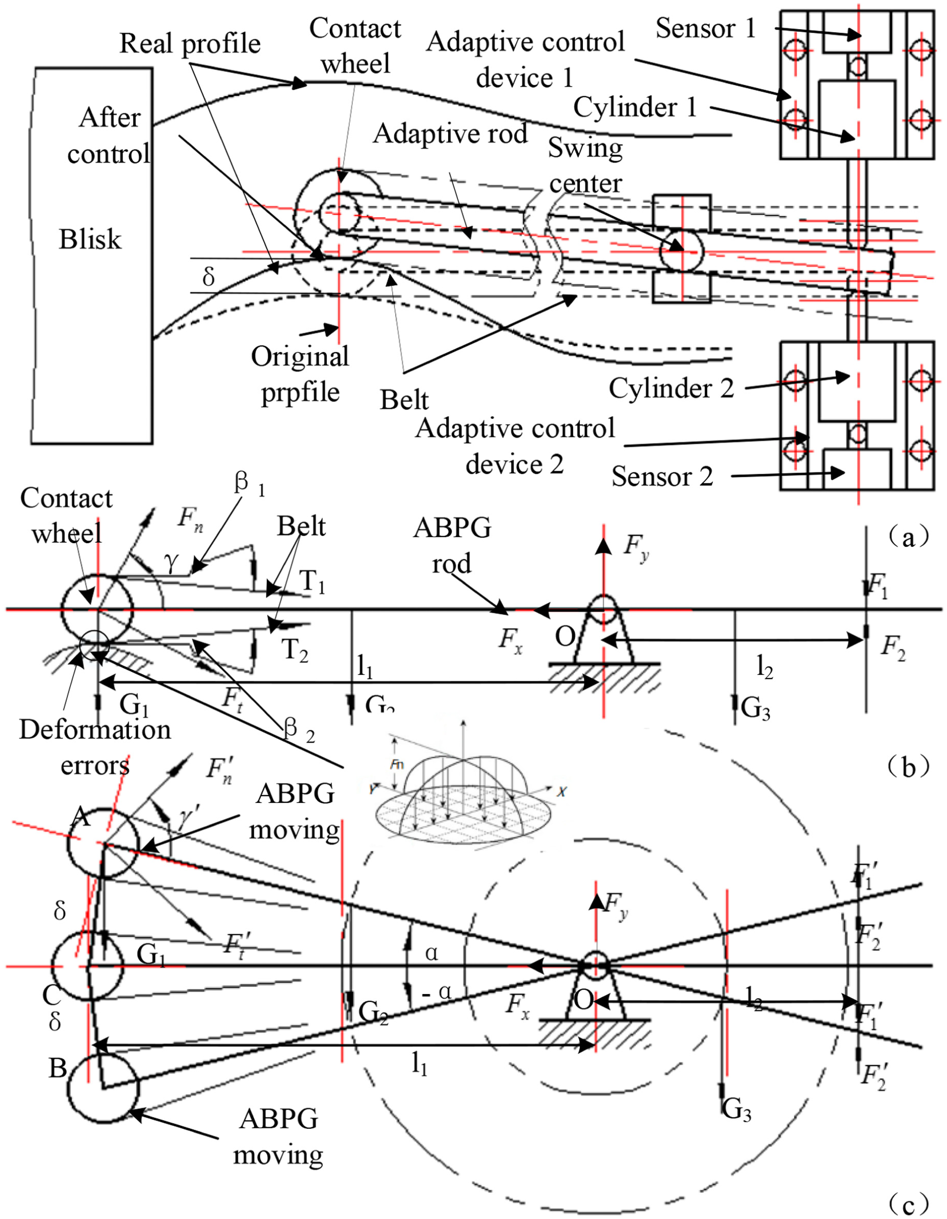
ABPG principle and the force analysis: (a) instruction for the mechanism, (b) force analysis, and (c) moving analysis.
As shown in Figure 2(b), the contact force
As shown in Figure 2(c), the force of the abrasive belt grinding for the blisk under the deformation synthetic errors δ, where state A is the force condition that the synthetic errors of blisk are positive, state B is the force condition that the synthetic errors of blisk are negative, and states A and B are analyzed respectively in this article. The pressure force rod would have tendency to move clockwise under state A, the pressure sensor 2 would have deformation, so the synthetic errors
Normally,


In

So

Because

According to equation (6), the length
The variation rule of axial force by synthetic errors and adaptive control parameters is shown in Figure 3. As shown in Figure 3(a), under different forces, synthetic errors have little effect on the axial force, but the influence of axial force on the material removal is very large, and the difficulty of force control is seriously increased; therefore, the calculation method of the axial force must be precisely controlled. As shown in Figure 3(b), under different errors, the axial force is proportional to the amount of force control, so it can be used to control accurately.

Change rule of axial force: (a) synthetic errors and (b) adaptive control parameters.
The variation rule of force differences by synthetic errors and adaptive control parameters is shown in Figure 4. As shown in Figure 4(a), the adaptive control is different from errors, and then the errors are increased with the increase of force control parameters. As shown in Figure 4(b), the force difference is proportional to the adaptive control parameters. As shown in Figure 4(a), the errors are changed from −0.1 to +0.1, and the force range is changed from 0 to 0.01; it has little effect on the pressure by the errors, so the four different δ have a same control line as shown in Figure 4(b).

Change rule of force range: (a) synthetic errors and (b) adaptive control parameters.
As shown in equation (6), the contact angle of axial force is

The axial force control errors

In the actual belt grinding process,
Adaptive control for precision material removal
The principle of belt precision grinding for the blisk leading and trailing edge is shown in Figure 5. The principle diagram of belt grinding of the blisk leading and trailing edge is shown in Figure 5(a). Belt grinding is a type of flexible grinding. The material removal is influenced by many factors, including belt speed Vs, grinding depth ap, grinding force F, elastic force FE, and centrifugal force Fω, as shown in Figure 5(b).
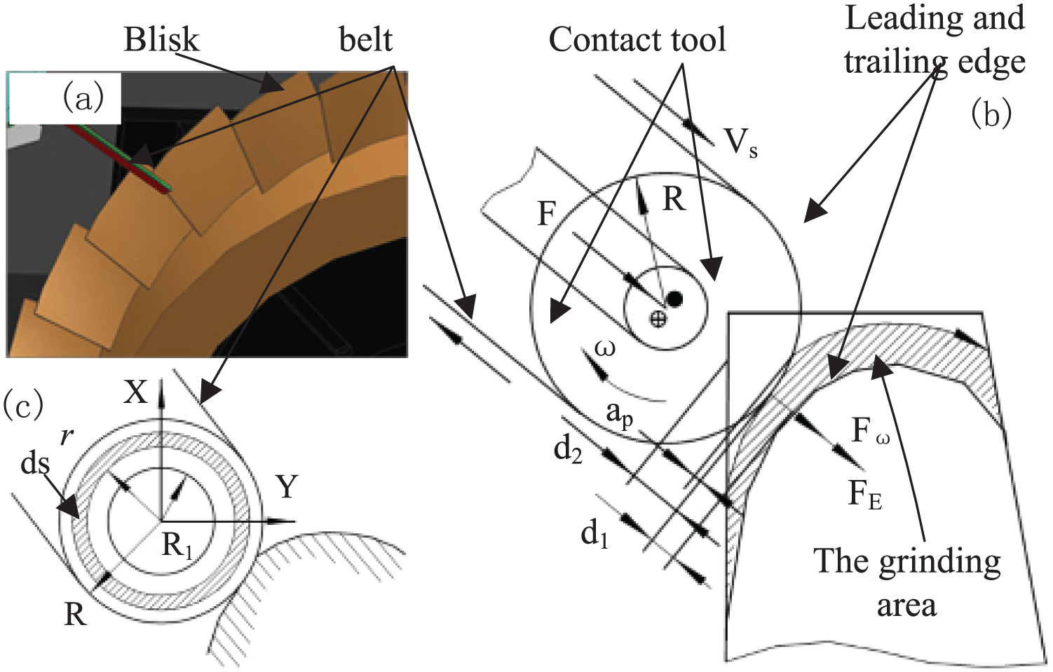
The principle of leading and trailing edge grinding: (a) blisk belt grinding mechanism, (b) edge grinding moving, and (c) mathematics modeling of grinding moving.
The motion model of the belt grinding for blisk is shown in Figure 5; the force is obtained

And then

And then

According to the contact theory of rigid cylinder and elastic hemisphere space

In order to realize the accurately control of force, when

The

Due to the micro-feed of the belt grinding process, it can be set,

When
When
According to the above analysis, the deformation of the blisk leading and trailing edge is huge with the heavy belt grinding, so it is difficulty to precision control the material removal of, and it should be avoided for the small allowance of blisk leading and trailing edge, but it is useful for efficiency. So, the heaving and elastic complex grinding should be used for the precision manufacture of the blisk leading and trailing edge.
Experiment aims and methodology
Equipment for experimental research
The belt grinding experiment for blisk leading and trailing edge was carried out on an independent made belt grinding equipment with a high precision computerized numerical control system for six-axis linkage movement, as shown in Figure 6. The experimental equipment, which including the new belt grinding head, high precision rail and turntable, lightweight bed and column, and so on. The blisk leading and trailing edge could be grinding under disposable clamping with this equipment, and the influence of the repeated clamping errors on the surface precision could be reduced.
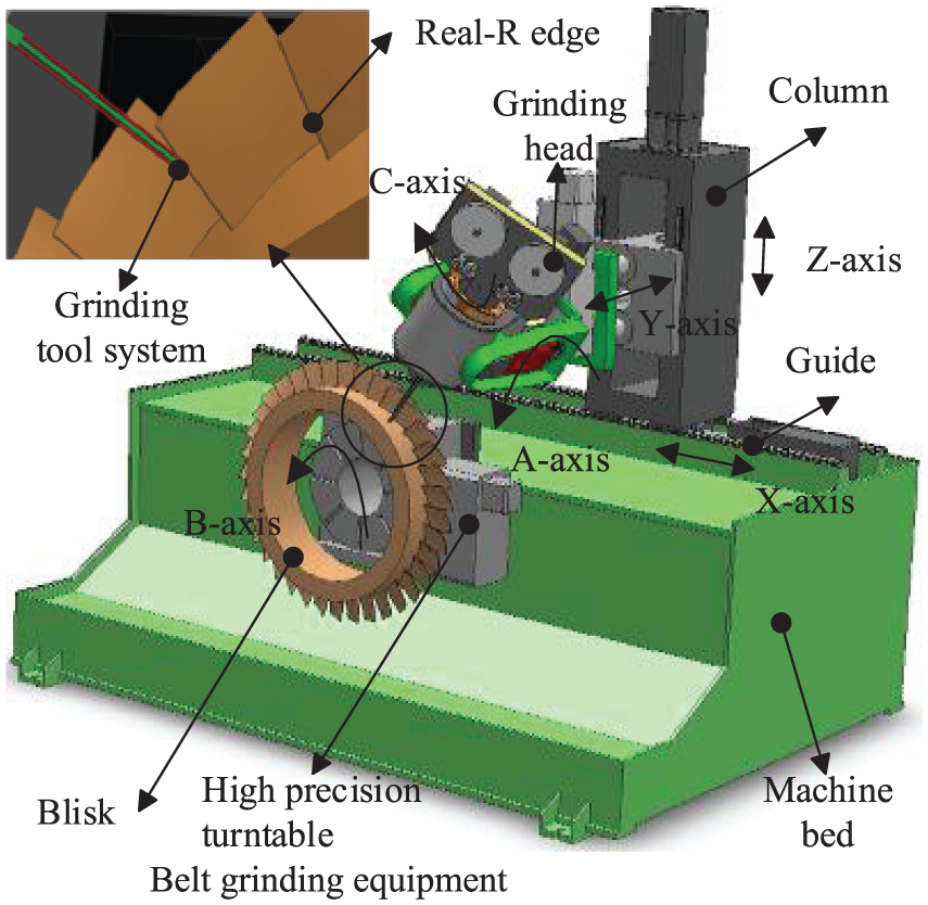
Belt grinding equipment.
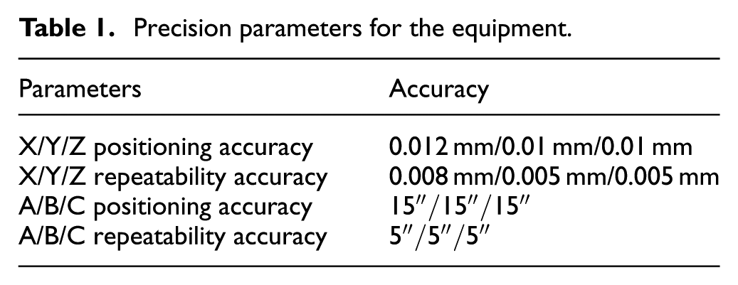
The equipment is designed by the structural of the blisk, and the realized method including. (1) The grinding feeding, grinding head, and workpiece azimuth angle are rationally allocated. (2) The rigidity of grinding head and workpiece clamping are ensured with the short transmission chain of 6° moving. (3) The stable contact between the contact wheel and the workpiece is guaranteed under high speed of contact wheel, through the contact wheel and belt could penetrate into the narrow gap of blisk between two blades. The parameters used for the precision grinding of the root fillet of blisk are shown in Table 1.
Precision parameters for the equipment.
Device for adaptive control
Belt grinding with double functionality of polishing and grinding, and also it has the characteristic of flexibility and adaptability. So, the excellent high-efficiency material removal properties and good surface machining quality can be fully realized for curved surface machining. The process also has a good fitting effect in terms of smooth curved surface transitions, and in combination with the elastic grinding characteristics of abrasive belt grinding, it is a very effective method to meet the small margin and area, high surface integrity requirements for the complex surface of blade.
The accuracy requirements for aircraft engine blade machining are very high, and thus, the blade grinding pressure must be controlled precisely during grinding process. In order to meet the technological requirements of blisk leading and trailing edge with belt grinding, the grinding equipment scheme must have a function such that it is able to provide feedback and the pressure must be adjustable.
Based on the method of six-axis linkage movement, for the characteristics of flexible contact between the blisk surface and belt, in order to adaptive control for blade deformation, the double force control method is shown in Figure 7. A mathematical model of the material removal process in blade edge grinding is set up based on grinding experiments, from which grinding parameter values at the grinding point can be obtained.

Device for adaptive control.
Experimental parameters and testing method
The blisk is clamped on the high precision turntable, and the belt grinding head is mounted on the lightweight column, which is shown in Figure 8(a). The precise positioning for this equipment is realized through the high precision computer numerical control system. The grinding manufacture is shown in Figure 8(b).

Belt grinding experiment: (a) blisk belt grinding, (b) contact condition, and (c) testing planning.
The experimental blisk sample is a part of an aero-engine blisk; its material is nickel-based superalloy (GH4169) and has passed the precision milling manufacture. The testing planning is shown in Figure 8(c). The blisk leading and trailing edge with Num. 1#–6# are tested to analysis the profile accuracy and surface quality for trailing and leading edge. A three-coordinate measuring instrument (Global Silver 05.07.05) was used to measure the PSP, and the surface roughness was measured by a surface roughness instrument (Times, TR200); the measurement length was 0.3 mm and the evaluation length was 0.05 mm.
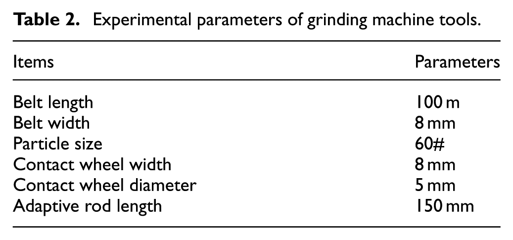
P1–P3 is testing point of the surface roughness; each point measured three times, and the result is the average surface roughness. L1–L3 is testing line for the profile precision of blisk leading and trailing edge. The belt grinding speed is 2 m/s, the grinding head feed speed is 0.5 m/min, the contact force is 10 N, the grinding height is 0.04 mm, the vibration frequency of reciprocating motion is 20 Hz, and the vibration length of reciprocating motion is 2 mm. And other experimental parameters are shown in Table 2.
Experimental parameters of grinding machine tools.
Results and discussions
Surface roughness
As shown in Figure 9, the surface roughness of leading and trailing edge Ra ranges from 0.751 to 1.086 μm by precision milling, and then the surface roughness of leading and trailing edge Ra ranges from 0.151 to 0.231 μm by ABPG. It can be seen that the surface roughness and consistency of blisk leading and trailing edge were improved obviously after belt grinding.

Surface roughness of (a) leading edge and (b) trailing edge.
This is mainly because of the flexible characteristics of belt grinding, and then the contact between belt and leading and trailing edge is plane, so the collapse grain and coolant are contained in the contact plane, and then the good surface roughness is obtained.
Profile precision
In order to analyze the grinding effect on the blisk leading and trailing edge, the leading and trailing edge profile is obtained by analyzing the three-coordinate testing results, as shown in Figures 9 and 10.

Profile shape of (a) leading edge and (b) trailing edge.
According to Xiao and Huang, 17 although the blade dimensional precision is under the errors after milling, as shown in Figure 11, the profile errors are still could not meet the requirements, because there are some profile shape errors, which includes chamfered edge, sharp edge, flat edge, obtuse edge, and cervical part shrinkage. Although in the later there will be some grinding edge over cut phenomenon, but after grinding the edge contour accuracy is obviously improved, especially the profile is transferred smoothly, and then the dynamic performance of the aero-engine would be improved.

Typical profile errors of the blade edge: 17 (a–d) chamfered edge, (e, f) flat edge, (g, h) cervical part shrinkages, (i) obtuse edge, and (j, k) sharp edge.
According to the above analysis, in order to accurately analyze the profile shape, combining the profile precision (PP), the following calculation formula is put forward to express the profile shape (PS) errors

Where PSP is
The parameter of K.

PSP of leading edge is shown in Figure 12(a) and the PSP of trailing edge is shown in Figure 12(b). From the above-mentioned analysis, the leading and trailing edge is not blindly reduced after belt grinding, the leading and trailing edge would be increased, so the method would be used to optimize the edge profile.

Analysis of PSP on blisk blade edge: (a) PSP of leading edge and (b) PSP of trailing edge.
The profile shape errors of blisk leading and trailing edge are analyzed in Figure 13, where the profile shape errors of leading edge between the realistic and theoretical are shown in Figure 13(a), the profile shape errors of trailing edge between the realistic and theoretical R are shown in Figure 13(b). It can be seen that the profile shape errors of the leading and trailing edge are very larger after milling, the max errors of leading edge are −58%, and the max errors of trailing edge are 70%. After grinding, the leading and trailing errors of leading and trailing edge are less than 20%. At the same time, it can be seen that the profile shape errors of L2 varied greatly, and the error distribution is greater than other testing lines; this is mainly due to the method of ABPG to adaptive the blisk deformation for the blade tip, and the error caused by the blade deformation can be reduced. According to the above analysis, the profile shape errors of leading and trailing edge are obviously improved with the testing data for leading and trailing edge, the testing results show that the material removal control and ABPG is reasonable, and the theoretical and experimental study is provided for foundation with this research.

Analysis of PS errors on blisk blade edge: (a) PS errors of leading edge and (b) PS errors of trailing edge.
Conclusion
The method of ABPG is used to improve leading and trailing edge profile shape errors of the blisk. First, the methodology of ABPG for blade deformation and material removal precision is analyzed by the characteristics of blisk leading and trailing edge, the blade deformation errors are compensated by the detection and control of the contact pressure, and the precision grinding is achieved by controlling rotating speed of the contact wheel according to the contact between the belt and blisk leading and trailing edge. And then, the experiment of the belt grinding technology for the blisk leading and trailing edge is applied to verify this method, and at the same time, the device for ABPG is illustrated. The experimental results show that for the leading and trailing edge after ABPG, the surface roughness is less than 0.4 μm, the profile shape errors are less than 20%, and the surface glossy transition between the blade surface and the leading and trailing edge. It is proved that the method of ABPG might be considered as a viable process for blisk precision manufacture.
Footnotes
Handling Editor: Xichun Luo
Declaration of conflicting interests
The author(s) declared no potential conflicts of interest with respect to the research, authorship, and/or publication of this article.
Funding
The author(s) disclosed receipt of the following financial support for the research, authorship, and/or publication of this article: This work was supported by National Natural Science Foundation of China (grant no. 51705047) and the fundamental research funds for the central universities (grant no. 106112017CDJXY110005).