
Abstract
Compared with the rigid hand rehabilitation robot, the soft hand rehabilitation robot has the advantages of good flexibility, which is of great significance to its research. In order to make the soft hand rehabilitation robot have the advantages of high stiffness and simple manufacturing process, a nested structure is proposed for finger soft actuator in this paper. The nested structure consists of outer restraint structure and inner core structure. The inner core structure can realize deformation under the action of air pressure. The outer restraint structure can improve bending efficiency by restraining deformation in non-functional direction of inner core structure. On this basis, the processing technology of nested structure is designed, and the effect of structural parameters on performance is analyzed. In order to illustrate the advantages of nested structure, the performance of nested structure and fiber-constrained structure is compared by simulation, which includes bending angle, gripping force and expansion amount (by measuring the deformation of the cross section). The simulation results show the advantages of the nested structure. A prototype of the soft hand rehabilitation robot is developed with nested structure as finger soft actuator, and the experimental results prove the feasibility of design. The results of this study provide a reference for the structure design of soft hand rehabilitation robot.
Introduction
For the most hand rehabilitation robots, the main structure is made of metal or resin, and the structure is rigid.1–3 With the rapid development of material science, some researchers have begun to use soft material instead of traditional rigid material to develop new type of hand rehabilitation robot. Soft hand rehabilitation robot has the advantages of good motion flexibility and light weight. It is one of the development trends of hand rehabilitation robot. 4
The main structure of the hand rehabilitation robot is finger soft actuator. Soft actuator contains one or more seal cavities, and it deforms under the action of air pressure. Common deformation includes elongation deformation, bending deformation and composite deformation. 5 Since the fingers can be approximately equivalent to a series mechanism with multi-rotation joints, the bending deformation of the soft actuator is chosen for the most finger soft actuator. Different structures have a great effect on the driving performance. Therefore, researchers have designed many structures for soft hand rehabilitation robots.
According to the number of degree of freedom (DOF), soft actuator can be divided into two types: continuous cavity and segmented cavity. For the former, all cavities are connected, and the DOF of soft actuator is one. Its structure is relatively simple. One of the most typical is the soft actuator developed by Harvard University. The soft actuator has a connected cavity, and each finger is bent along a specific trajectory under the action of air pressure. The rehabilitation robot can assist the patient to grasp the object.6,7 Zhao et al. 8 designed the structural shape of the continuous cavity. Each of the five fingers is made of a series of interconnected hollow spherical chambers. The experimental results show that it has good movement effect. Besides, Antonelli et al., 9 Zhang et al., 10 Yap et al., 11 and Zhong-Sheng et al. 12 also studied the soft actuator with a single sealed cavity and analyzed its performance in detail. For the segmented cavity, the cavities are not connected. It needs multiple drivers and has a more complex structure, but has better flexibility. For example, Wang et al. 13 designed a segmented soft structure for the soft pneumatic glove. The segmented structure of the actuator is designed according to the anatomy of human fingers, which makes the actuator fit with finger better than those of homogenous structure. Chen et al. 14 designed a novel bending soft pneumatic actuator. The soft body comprises two identical chambers, which were cast together through the middle layer that was integrated with nonstretchable fiberglass fabric. It can realize bidirectional bending deformation. Besides, Wang et al. 15 and Yan et al. 16 also designed the multi DOF soft actuator through multi-cavity design.
In particular, In addition to kinematic flexibility, structural stiffness is also one of the important performance of finger soft actuator. Due to the deformation of soft material itself, the soft actuator has the problems of poor stiffness and insufficient output force. When the hand muscles of the recovered patients have large uncontrollable muscle force, it is hard for a soft actuator to drive a patient’s fingers to grasp heavy objects. Common ways to increase stiffness include increasing the constraint fibers and increasing the rigid particles. Fiber reinforcement enables soft robots to create sophisticated motions and loading, including axial extension, rotation, and torsion.17,18 For example, Shiota et al. 19 proposed a soft thumb rehabilitation device which is based on a parallel-link mechanism. Fiber-reinforced elastomer actuators is used, which could help to resist part of the tearing force. Singh and Krishnan 20 presented a method for designing fiber-reinforced soft actuators to match a planar curve, which can generate a wide variety of deformation behavior. For the rigid particles, Jiang et al. 21 propose a novel, high DOF variable stiffness joint. By pulling granule filled membrane-columns under vacuum, the columns and joint stiffen as the granular matter begin to jam, and a four-fold increase in stiffness is achieved. Thompson-Bean et al. 22 presented the development and design of an exoskeleton for the hand, utilising a physical phenomena known as granular jamming, where pressure within a soft membrane is varied to cause a granular material to change from a solid to fluid-like state. The experimental results show that increasing the chamber size of a jammed granular beam increases the generated resistive forces. However, the use of fiber increases the difficulty of processing of soft actuator, and the stiffness of the structure does not increase to the ideal value. The rigid particles only can make the soft actuator achieve great stiffness at the end of the motion, and have less effect on the stiffness during the deformation process.
In order to make the soft actuator have the advantages of simple structure, high stiffness and simple process, and realize complex motion at the same time, a finger soft actuator with nested structure is designed. On this basis, the processing technology and performance are analyzed in detail through simulation and experiment. The analysis results prove the feasibility of structural design.
Structural design
Structure of soft actuator
The soft actuator requires that large deformation under the action of air pressure to drive the bending of fingers. Soft actuator generally consists of three parts, namely deformation layer, non-deformation layer and deformation restraint layer. The deformation layer is the main structure of the soft actuator. Under the action of air pressure, the material expands to achieve directional deformation. The non-deformation layer is used to control the deformation form of the soft actuator, such as bending or elongation. Deformation restraint layer is used to restrain deformation in non-functional direction to improve motion efficiency.
The commonly used deformation restraint structure is filament, and the assembly process is complex. In order to enable the soft actuator to realize the advantages of high stiffness, simple assembly and can restrict deformation in non-functional directions, a nested structure is designed, which can be seen in Figure 1. The nested structure consists of inner core structure and outer restraint structure. The inner core structure is a hollow sealed structure, which is the main structure to realize bending deformation. The outer restraint structure is composed of a bottom solid structure and restraint structure formed by array. The bottom solid structure acts as a non-deformed layer. It is used to limit the deformation form of inner core structure. The inner radius of restraint structure of array distribution (RO1, which is shown in Figure 1) is equal to the sum of outer radius of inner core structure (R+T, which is shown in Figure 1) and bottom thickness of inner core structure (BI, which is shown in Figure 1). It prevents the inner core structure from deforming along the non-functional direction, and it is also used to change the deformation form of the soft actuator. By inserting the inner core structure into the outer restraint structure, a nested soft actuator is formed. With the increase of air pressure in the inner core cavity, large bending can be achieved. In Figure 1, L is the total length of soft actuator, and it is different for different fingers. D is the width of restraint structure of array distribution. By changing the size of the parameter D at different locations, different deformation effects can be achieved for the soft actuator. RO and RO1 are the inner radius and outer radius of restraint structure of array distribution, respectively. BI and BO are the bottom thickness of inner core structure and outer restraint structure, respectively. R is the cavity radius, and T is the cavity wall thickness.
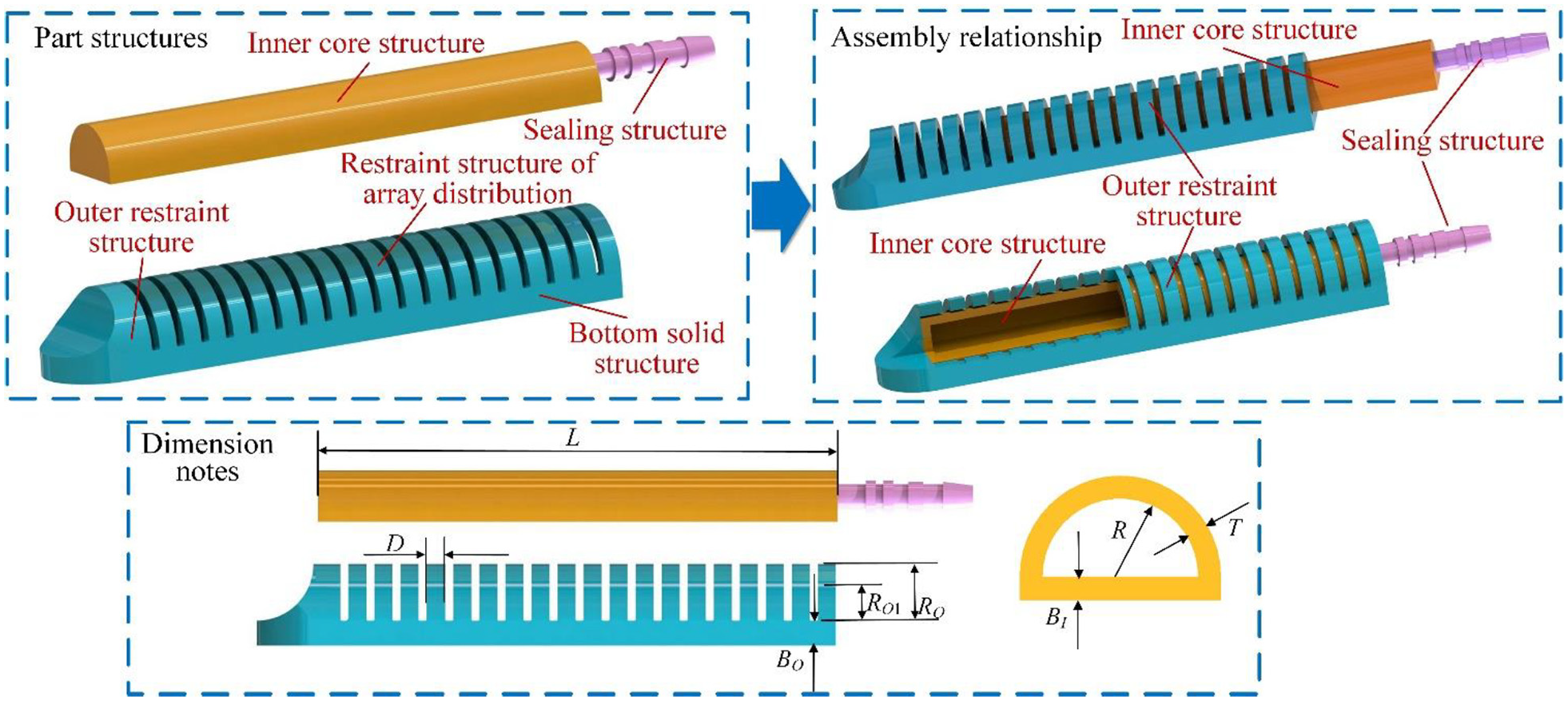
Diagram of soft actuator with nested structure.
Processing technology
The material of soft actuator is silica gel. The Shaw hardness range of silica gel is 10–15 HA/HDw. Its tensile rate is 500–600%, and its tear resistance is 10–20 kN/m. This kind of silica gel has the advantages of softness, good fit with human skin and strong elasticity. The product is made up of two parts, and they are liquid at room temperature. In the production process, two kind of liquid are mixed in proportion of 1:1. After full stirring, they can be solidified at room temperature for 12 h or at 60°C for 2 h.
The technological process of soft actuator with nested structure can be divided into two parts, namely, the inner core structure preparation process and the outer restraint structure preparation process. The preparation process of inner core includes die manufacturing, liquid silica gel casting and cavity sealing, which is explained in detail as follows.
Manufacture of inner core die
There are two parts in the manufacture of the die for the inner core structure, including the inner core cavity forming die and inner core structure forming die. For the inner core cavity forming die, the paraffin wax is used as the die material. The iron core is inserted into the paraffin wax die cavity to fix it, which can be seen in Figure 2(a). For the inner core structure forming die, its structure is shown in Figure 2(b). The die includes an upper cover plate, a sealed port and an inner core structure forming cavity.

Diagram of technological process: (a) inner core cavity forming die, (b) inner core structure forming die, and (c) overall process flow of soft actuator with nested structure.
Preliminary forming of inner core structure
Put the inner core cavity forming die into inner core structure forming die. The liquid silica gel is injected into the forming chamber, and the cover plate is assembled to wait for the silica gel to solidify naturally. Then the inner core structure is removed from the die. The inner core structure is heated as a whole, and the filled paraffin wax die was transformed into a melt state and flows out from the inner core cavity. The inner core structure with two openings at both ends is preliminarily obtained.
Seal up
One side of the inner core structure is immersed the groove filled with liquid silica gel. The other side of the inner core structure is filled the ventilation connector, and the final inner core structure can be obtained by sealing with liquid silica gel.
The preparation of the outer restraint structure is different from the preparation method of the inner core structure. In order to prevent the adhesion of the restraint structure of array distribution, the outer restraint structure can be rapidly formed by injection molding. It can be prepared by 3D printing. The preparation process of the soft actuator with nested structure is shown in Figure 2(c).
Performance analysis
Parameter analysis
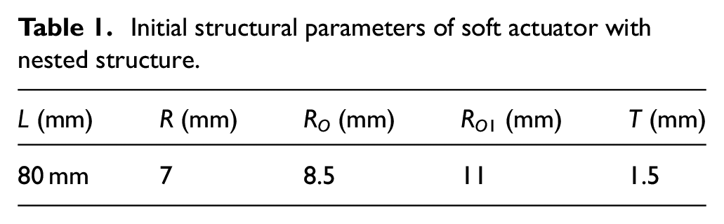
For soft actuator, the main performance includes bending angle and grasping force. The bending angle refers to the angle change of the tangent line of the curve end point of the soft actuator, which reflects the motion effect of the soft actuator, that is, whether it can realize the basic function. The grasping force refers to the force that is perpendicular to the tangent of the end point of the soft actuator, and it prevents the bending of the soft actuator. Grasping force reflects the stiffness of the soft actuator. When the actuator has a large stiffness, the end of the soft actuator can output a large grasping force, instead of the air pressure being offset by the deformation of the soft material itself. The parameters that affect the performance of soft actuator with nested structure include the thickness of the bottom (including outer restraint structure and inner core structure), and the width of the restraint structure of array distribution. Suppose the length L is 80 mm. If the radius is too large, the adhesion between the soft actuator and the finger may be poor. Considering the coupling relationship between the cavity wall thickness T and the radius at the same time, RO, RO1, R and T are set to constant values, which can be seen in Table 1. Simulation is conducted to analyze the performance by ABAQUS. The effect of parameters on performance is analyzed as follows.
Initial structural parameters of soft actuator with nested structure.
Thickness of the bottom
For the outer restraint structure, when the range of thickness of the bottom solid structure BO is [1 mm, 4 mm] (Figure 3(a)) and the air pressure is 0.25 Mpa, the effect of the bottom thickness BO on the kinematic performance is shown in Figure 3(b) and (c). When the bottom thickness BO increases, the bending angle tends to decrease. When the bottom thickness BO is 1 mm, the bending angle is about 318.6° under the pressure of 0.25 Mpa. When the bottom thickness BO is 4 mm, the bending angle of the soft actuator is about 245.4° under the same pressure, reduced by 73.2°. For the grasping force, its changing trend is the same as that of bending angle. When the bottom thickness BO increases from 1 mm to 4 mm, the grasping force decreases from 1.68 N to 1.32 N. The above analysis results show that thickness of the bottom solid structure BO should be small to ensure a large bending angle and a large grasping force. However, too small BO will increase the difficulty of processing technology and increase the manufacturing cost.

Effect of the thickness BO of the bottom of outer restraint structure on performance: (a) diagram of change of BO, (b) bending effect of soft actuator, and (c) change of bending angle and grasping force.
In particular, the effect of bottom thickness BO on performance is also related to the air pressure. When the air pressure is 0.02 Mpa, the bending angles corresponding to BO of 1 mm and 4 mm are 129.6° and 115.2°, respectively. The grasping force corresponding to BO of 1 mm and 4 mm are 1.2 N and 1.05 N, respectively. BO has little effect on performance. Therefore, the expected input air pressure should also be considered in the structural design.
For the inner core structure, when the range of bottom thickness of inner core structure BI is [1 mm, 4 mm] (Figure 4(a)), the effect of the bottom thickness BI on the performance is shown in Figure 4(b) and (c). The effect trend of the bottom thickness BI on the grasping force is the same as that of the outer restraint structure. When the bottom thickness BI increases, the grasping force decreases from 1.76 N to 1.38 N, reduced by 22%. For the bending angle, with the increase of the bottom thickness BI, the bending angle increases first and then decreases. When BI = 1 mm, the bending angle is about 259°. When BI = 2 mm, the bending angle is about 288.6°. After that, with the increase of BI, the bending angle decreases continuously. This shows that bottom thickness BI cannot be too small, and proper increase of BI is conducive to good performance.

Effect of the thickness of the bottom BI of inner core structure on performance: (a) diagram of change of BI, (b) bending effect of soft actuator, and (c) change of bending angle and grasping force.
Width of restraint structure of array distribution
When the range of width D of restraint structure of array distribution is [2 mm, 5 mm] (Figure 5(a)), the effect of the width D on the performance is shown in Figure 5(b) and (c). When the width D is 2 mm and 3 mm respectively, the outer restraint structure breaks during the bending process. This shows that the width D should not be too small, otherwise it will not only restrict the deformation of the inner core structure in the non-functional direction, but also affect the normal movement of soft actuator. When the width D increases from 4 mm to 5 mm, the bending angle decreases from 236.8° to 236.8° under the pressure of 0.25 Mpa, and the grasping force decreases from 1.66 N to 1.6 N under the same air pressure. This shows that the width D of restraint structure of array distribution cannot be too large or too small, and the value should be taken to ensure that the soft actuator cannot only achieve normal movement, but also have a large bending angle and grasping force.

Effect of the width D of restraint structure of array distribution on performance: (a) diagram of change of D, (b) bending effect of soft actuator, and (c) change of bending angle and grasping force.
In the above analysis, regardless of the value of width D, the whole restraint structure is a uniform array. When the width D of different position is different, the motion effect of the soft actuator will be greatly different. For example, there are two different width D for the restraint structure. There is a large width D1 for every five groups of structures with width D = 3 mm (Figure 6(a)).When the large width D1 is 9 mm, 12 mm, 18 mm and 24 mm respectively, the bending effect of the soft actuator is shown in Figure 6(a). When the fixed coordinate system is built on the fixed end of the soft actuator and more groups of different D1 are considered, the bending curve is shown in Figure 6(b). As can be seen from the Figure 6, when the width D of different positions is the same (D = D1 = 3 mm), the bending effect is similar to a circle. When the thickness of different positions of restraint structure of array distribution is different, the bending effect is different, and the bending angle also changes. Because people with different diseases and different ages have different finger bending trajectories during rehabilitation, the bending trajectory can be changed by changing the width distribution of the outer constraint structure to meet the needs of different groups.

Effect of the width distribution of restraint structure on performance: (a) diagram of change of width distribution and (b) bending trajectory with different D1.
In conclusion, the thickness of the bottom (outer restraint structure and inner core structure) and the width of the restraint structure of array distribution has a great effect on the bending effect and grasping force of the soft actuator. Except for thickness of out restraint structure, thickness of inner core structure and width distribution of the outer constraint structure cannot be too large or too small, and should be taken within a certain range.
Comparative study
In order to analyze the performance of nested soft actuator, fiber-constrained soft actuator is used as a comparison object. This is because fiber-constrained soft actuator also has high stiffness through fiber reinforcement, which is similar to the performance of nested soft actuator. Fiber-constrained soft actuator is shown in Figure 7. It consists of three parts: main deformed structure, non-deformed layer and fibers. The main deformed structure is a semi-circular hollow closed structure. Under the restraint of non-deformed layer and fibers, high-efficiency bending can be achieved. For the soft actuator with nested structure, suppose D = 3.5 mm, BI = BO = 2 mm, and T = 1.5 mm. For ease of comparison, the cross-section size and length are the same as those of soft actuator with nested structure. The structural parameters are shown in Table 2. The material of the main deformation structure is silica gel, which is the same as nested structure. The material of the non-deformation layer is paper.

Diagram of fiber-constrained soft actuator.
Structural parameters of fiber-constrained soft actuator.

Similarly, simulation is conducted to compare the two structures by ABAQUS. It is assumed that under the action of air pressure, the cavity is well sealed and there is no air leakage. For the performance indices, in addition to the bending angle and gripping force, the deformation of the cross section is further considered, which reflects the deformation efficiency of soft actuator. The larger the deformation of cross section in the non-functional direction, the lower the efficiency of the soft actuator.
Bending angle
If the soft actuator can drive the finger to achieve rehabilitation training, it needs to be able to achieve large angle bending deformation under the action of air pressure. When the air pressure is 0.03 Mpa, the bending sequence diagrams of the soft actuator with nested structure and fiber-constrained structure are shown in Figure 8(a). It can be seen from the Figure 8(a) that the bending angle of soft actuator with fiber-constrained is obviously large, and the maximum bending angle is about 130°. The bending angle of soft actuator with nested structure is very small, and the bending angle is only 16°. They are almost eight times different. The angle change is shown in Figure 8(d). When the air pressure in the cavity increases to 0.05 Mpa, the rotation angle of fiber-constrained soft actuator is approximately 360°. And rotation angle of nested soft actuator is only 26°. If the rotation angle of soft actuator with nested structure is close to 300°, the air pressure in the cavity should reach 0.3 Mpa, which is six times of the corresponding air pressure when soft actuator with fiber-constrained structure rotates for one cycle. The bending sequence diagram can be seen in Figure 8(c). The above analysis results show that the two different structures can achieve large deformation. However, due to the external restrictions of soft actuator with nested structure, it needs higher air pressure to achieve large deformation. In order to analyze the bending performance, the bending efficiency can be defined as

It indicates the deformation of the soft actuator under unit air pressure under the condition that the rotation angle Δθ is not less than the rated value θ0. For example, on the premise that both structures can achieve large bending angle, the rotational efficiencies of nested soft actuator and fiber-constrained soft actuator are 5.2 × 10⁴ and 3.2 × 10³, respectively. fiber-constrained soft actuator has higher bending efficiency.

Bending angle of nested and fiber-constrained soft actuator: (a) bending sequence diagram of soft actuator with 0.03 Mpa air pressure, (b) bending sequence diagram of soft actuator with 0.05 Mpa air pressure, (c) bending sequence diagram of nested soft actuator with 0.3 Mpa air pressure, and (d) change of bending angle of soft actuator.
Grasping force
The greater the grasping force is, the higher the stiffness of the soft actuator is, the better the finger can be driven to move the hand and complete the grasping of objects. The change of grasping force with the increase of the air pressure as shown in Figure 9(a). It can be seen from Figure 9(a) that for the nested soft actuator, with the increase of air pressure, the grasping force will increase continuously. When the air pressure is 400 Kpa, the grasping force is about 3.035 N. For the fiber-constrained soft actuator, when the air pressure range is increased in [0 Kpa, 150 Kpa], the grasping force increases rapidly. However, when the air pressure exceeds 150 Kpa, the grasping force will not increase. It can be known from Figure 9(b) and (c) that due to the low stiffness of fiber-constrained soft actuator, when the air pressure continues to increase, the deformation of the actuator’s own material offsets the increase of the air pressure, so that the grasping force cannot continue to increase. The maximum grasping force of fiber-constrained soft actuator is 1.225 N, far less than the maximum gripping force of nested soft actuator.

Change of grasping force for soft actuator: (a) change of grasping force, (b) attitude of the fiber-constrained soft actuator with 400 Kpa air pressure, and (c) attitude of the nested soft actuator with 400 Kpa air pressure.
The deformation in the non-functional direction also indirectly reflects the stiffness of the structure. The stiffness index can be defined as

where, ΔH is the maximum distance that the soft actuator moves in reverse along the initial horizontal line, which can be seen in Figure 9(b). When the pressure is 400 Kpa, ΔH of fiber-constrained soft actuator is about 30 mm, and ΔH of nested soft actuator is almost zero. When the offset amplitude is large, the stiffness of the soft actuator is insufficient, and the large deformation in the non-functional direction will lead to the failure of the task. According to the above analysis, the stiffness of soft actuator with nested structure is significantly higher than that of soft actuator with fiber-constrained structure.
Deformation of cross section
Cross-section deformation refers to the deformation of cross-section in the horizontal and vertical direction. The larger the cross-section deformation is, the larger the deformation in the non-functional direction of the soft actuator is, and the lower the motion efficiency is. For example, when the air pressure is 0.05 Mpa, the cross sections of nested structure and fiber-constrained structure are shown in Figure 10. The maximum deformation of soft actuator with nested structure along the horizontal direction (ΔSh shown in Figure 10) and vertical direction (ΔSV shown in Figure 10) are 0.27 mm and 0.08 mm, respectively, and that of fiber-constrained structure are 1.06 mm and 0.38 mm, respectively. When the air pressure is 0.3 Mpa, the maximum deformation ΔSh of the inner structure of the soft actuator with nested structure is 3.9 mm, but due to the limitation of the outer restraint structure, the final maximum deformation is 1.05 mm. This shows that the outer restraint structure effectively limits the deformation of the soft actuator along the non-functional direction. Therefore, the deformation of the soft actuator with nested structure is smaller, which is the reason why it can obtain larger grasping force.

Change of cross section of soft actuator: (a) change of cross section of soft actuator with fiber-constrained structure and (b) change of cross section of soft actuator with nested structure.
Generally speaking, soft actuator with nested structure has the advantage of high stiffness, large grasping force and small cross section deformation on the premise of large bending deformation, and its comprehensive performance is better than soft actuator with fiber-constrained structure. This proves the feasibility of the design in this paper.
Parameters determination
In order to further determine the parameters of the soft actuator with nested structure by optimization method, the function is defined as

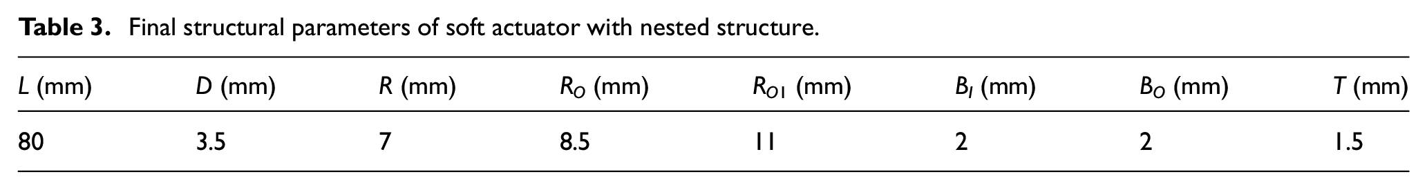
where, λi is proportionality coefficient, and λ1+λ2+λ3+λ4+λ5=1. By adjusting the proportionality coefficient, the weight of different performance can be adjusted. Variables include the width of restraint structure of array distribution D (consider only cases where D is all equal), the bottom thickness of inner core structure and outer restraint structure BI and BO. Function values should be as small as possible. The ranges of the D, BI and BO are [3 mm, 5 mm], [1 mm, 4 mm] and [1 mm, 4 mm], respectively. The datas of the effect of a single parameter on performance are fitted, and 50 sets of values are randomly taken within the ranges. A set of values corresponding to the minimum objective function F is the final result. The final parameters thus determined are shown in Table 3.
Final structural parameters of soft actuator with nested structure.
Experiments
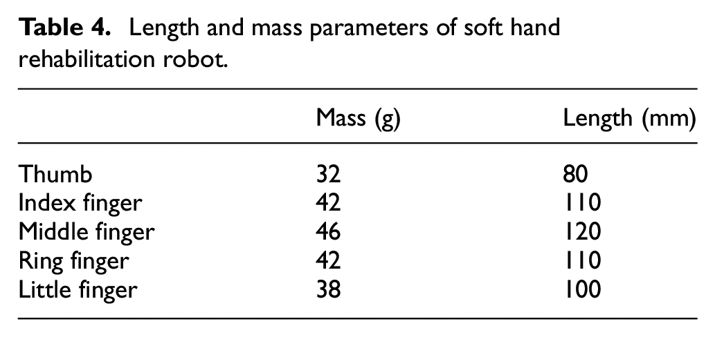
In order to verify the correctness of the analysis results, the prototype of the soft hand rehabilitation robot with nested structure is developed, which can be seen in Figure 11. The experimental system can be seen in Figure 11(a), which consists of soft hand rehabilitation robot, control system and pneumatic system. Each finger is driven by a separate pneumatic system. The soft actuator with nested structure is shown in Figure 11(b). In order to wear conveniently, gloves are added to the outside of the soft robot, which is made of nylon cloth. The final prototype is shown in Figure 11(c). The length and mass parameters of the robot are shown in Table 4.

Prototype of soft hand rehabilitation robot: (a) system composition, (b) prototype of soft actuator with nested structure, and (c) soft hand rehabilitation robot with gloves.
Length and mass parameters of soft hand rehabilitation robot.
Finger movement experiment
In order to prove that the soft actuator can drive the fingers to achieve the desired movement, two groups of experiments were carried out, namely five-finger bending experiment and thumb and index fingertip contact experiment, which can be seen in Figure 12(a) and (b), respectively.

Sequence diagram of finger movement experiment: (a) five-finger bending and (b) fingertip contact between thumb and index finger.
The relationship between the bending angle of each finger and the air pressure is shown in Figure 13. It can be seen in Figure 13(a) that all five fingers have obvious bending deformation under the action of air pressure for the five-finger bending experiment. When the pressure is the same, the soft actuator of the thumb has the smallest bending angle. When the air pressure is 80 Kpa, the bending angle is about 45°. The change of bending angles for other four fingers are nearly the same. When the air pressure is 80 Kpa, the bending angle is about 80°. For the thumb and index finger fingertip contact experiment, the relationship between the bending angle of each finger and the air pressure is shown in Figure 13(b). When the air pressure is 70 Kpa, the bending angle of thumb is about 30°, and the bending angle of the index finger is about 70°. In addition, according to the statistical results of nine groups of experiments, the maximum bending angle of each finger for five-finger bending experiment can be seen in Figure 13(c). For the thumb, the mean and variance were 45° and 2.92, respectively. For the little finger, the mean and variance are relatively large, 90° and 9.17, respectively. The experimental results show that the repetitive motion can still meet the motion requirement. It also shows that the structure has good air tightness. When each finger moves at the same angle, and the air pressure are shown in Table 5. The longer the soft actuator is, the less air pressure is needed to bend at the same angle.
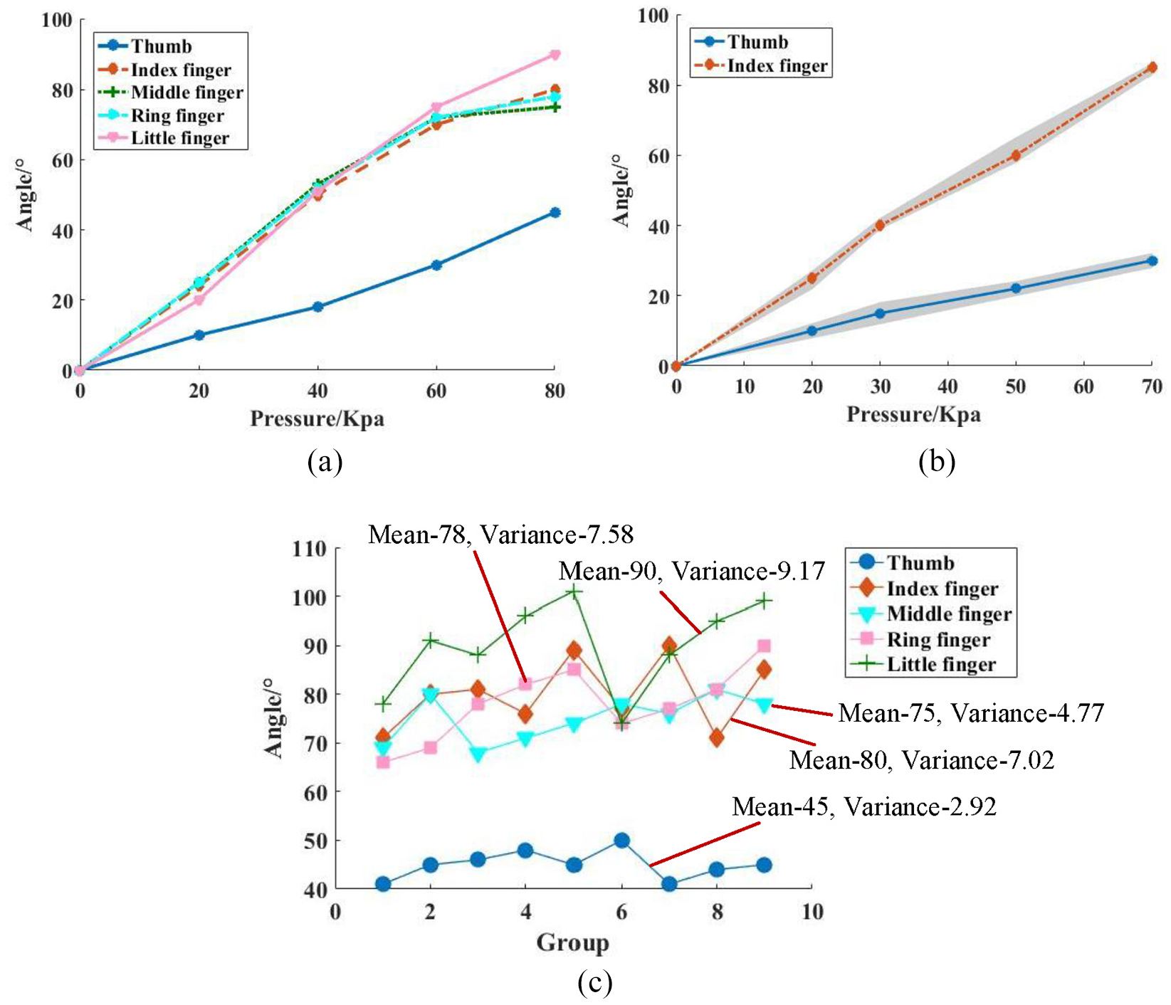
Change of bending angles: (a) change of bending angles for five-finger bending experiment, (b) change of bending angles for fingertip contact experiment, and (c) statistical results of nine groups of bending angles.
Pressure changes with the same angle.

Object grasping experiment
On the basis of the normal bending of the fingers, it is necessary to analyze the grasping performance to ensure that patients can perform target grasping training. Two groups of experiments were conducted. One group was to grasp a can (big cylinder, and the weight of the can is 100 g), which required five fingers to participate. The other group is to grasp a pen (small cylinder, and weight of the pen is 40 g), which requires only the thumb and index finger to participate. This corresponds to the finger bending experiment, and the sequence diagram of object grasping process for two cases are shown in Figure 14(a) and (b), respectively.

Sequence diagram of object grasping experiment: (a) grasping the big cylinder (can) and (b) grasping the small cylinder (pen).
When the soft actuator drives the fingers to grasp the can, the rotation angle and grasping force of each finger (the contact force between the end of the finger and the can) are shown in Figure 15(a) and (b). Figure 15(a) shows the change of bending angles and grasping forces of thumb, index and middle fingers, and Figure 15(b) shows the change of bending angles and grasping forces of ring finger and little finger. The contact forces are measured by pressure sensors attached to the end of the fingers. The data were the average of nine groups of experiments. It can be seen from Figure 15(a) and (b) that when the pressure is 20 Kpa, the fingers contact the can. When the pressure is 40 Kpa, the rotation angle of the actuator reaches the maximum. The angle change of the soft actuators is nearly the same as that of the finger movement experiment. The maximum rotation angle of the thumb is about 20°, and that of the other four fingers is about 60°. When the air pressure is 140 Kpa, the grasping force reaches its maximum. The grasping force of different fingers is different in the range of [0.9 N, 2.6 N]. The experimental result shows that the soft actuator can drive the fingers to grasp the can to leave the desktop. For the experiment of grasping pen, the rotation angle and grasping force of thumb and index finger are shown in Figure 15(c). The maximum grasping forces of thumb and index finger are 1.65 N and 2.07 N respectively. The pen can be accurately grasped and picked up by hand under the function of soft actuator.

Change of bending angles and grasping forces: (a) change of bending angles and grasping forces of thumb, index and middle fingers for gripping the can, (b) change of bending angles and grasping forces of ring finger and little finger for gripping the can, and (c) change of bending angles and grasping forces of thumb and index finger for gripping the pen.
The above experimental results show that the soft actuator with nested structure can drive fingers to achieve large bending angle and has stable and large grasping force. At the same time, it has good repeatability (good sealing). All of these prove that the design of nested soft actuator proposed in this paper is reasonable.
Conclusions
In order to enable the soft hand rehabilitation robot to achieve large deformation and high stiffness, design, analysis and experiment of finger soft actuator with nested structure are carried out.
A nested structure is proposed for finger soft actuator. It consists of outer restraint structure and inner core structure. The outer restraint structure can improve bending efficiency by restraining deformation in non-functional direction of inner core structure. Then the processing technology of nested structure is designed.
The effect of structural parameters on bending angle and grasping force is analyzed in detail. The analysis results show that for most structural parameters, too large or too small parameters will reduce the overall performance of the soft actuator. On this basis, the structural parameters are determined by the optimization method.
In order to illustrate the advantages of nested structure, the performance of nested structure and fiber-constrained structure is compared by simulation. The simulation results show that the structure of nested structure is simpler than that of fiber-constrained structure, and nested structure can have greater grasping force and smaller cross-sectional deformation.
A prototype of the robot is developed with nested structure as finger soft actuator, and the experimental results prove the feasibility of structural design.
The results of this study provide a reference for the structure design of soft hand rehabilitation robot. Further extensions to this work include material optimization, multi DOF structural design and complex task experiment to enable soft hand rehabilitation robot to assist patients at different rehabilitation stages to complete typical training tasks.
Footnotes
Handling Editor: James Baldwin
Declaration of conflicting interests
The author(s) declared no potential conflicts of interest with respect to the research, authorship, and/or publication of this article.
Funding
The author(s) disclosed receipt of the following financial support for the research, authorship, and/or publication of this article: This work was supported by the Project supported by the National Science Foundation for Young Scientists of China (Grant No. 51705201), the China Postdoctoral Science Foundation Funded Project (Project No.2018M630515), the Fundamental Research Funds for the Central Universities (Grant No. JUSRP11718), the Foundation of Jiangsu Key Laboratory of Advanced Food Manufacturing Equipment and Technology (Grant No. FMZ201804).