
Abstract
The microgripper based on the principle of lever amplification is easy to realize; however, the theoretical amplification factor is limited by the space size and the structure is not compact enough. The microgripper based on the triangular amplification principle has a compact structure and high amplification factor, but it is not conducive to miniaturization design. Considering compactness, parallel clamping, high magnification, and miniaturization design, a three-stage amplifier consisting of a semi-rhombic amplifier and lever amplifiers is designed. To begin with, the theoretical amplification ratio and the relationship between input variables and output variables are calculated by energy method. Furthermore, the finite element analysis software is used to optimize the structural parameters and analyze the performance of the model. Lastly, the experimental verification is carried out. At 150 V of driving voltage, the maximum output displacement was 530mm, and the actual magnification was 24 times. Microparts can be gripped in parallel and stably, which confirms the validity of the design.
Keywords
Introduction
In recent years, with the rapid development of high technologies such as micro-electro-mechanical systems (MEMS), research on micro-operation has made great progress and is now widely used in the aerospace, optical fiber alignment, precision processing, bioengineering, life science, communication engineering, and so on.1–6 The microgripper is a terminal manipulator that makes direct contact with a micro-object, and its performance can determine the success of the micro-assembly task. Compared with the traditional rigid mechanism, the flexible mechanisms have the characteristics of no friction, no clearance, and no assembly, which is more suitable for the application of a micro-operating system. 7
From the view of current research, the key issues in microgripper research are the selection of the driving mode, increasing the displacement magnification. Today, common driving modes of the microgripper include the piezoelectric drive,7,8 electrostatic drive,9,10 thermal drive,11,12 shape memory alloy drive,13,14 electromagnetic drive,15,16 and pneumatic drive.17,18 Compared with other driving modes, the piezoelectric drive has the advantages of fast response, high sensitivity, and large output force.19,20 Enlarging the gripping displacement magnification is mainly achieved by displacement amplifiers. The commonly used micro-displacement amplifiers are based on the principle of lever amplification and bridge amplification. The single-stage amplifier designed based on the principle of lever amplification is easy to realize; however, its structure is not compact enough and its theoretical amplification factor is limited by the size of space. Parallel gripping can be realized by adding parallel four-bar mechanism to improve the gripping accuracy, but it is not conducive to miniaturization design.21–24 The piezoelectric ceramics are placed inside the single-stage amplifier based on bridge amplification principle, which has compact structure and high amplification factor. Parallel gripping is realized by a two-way symmetrical input force. However, some problems are not conducive to miniaturization design.25–28 A multi-stage amplifier can further expand the gripping stroke of the microgripper and increase the degree of magnification, and the research on the multi-stage amplifier has gradually increased in recent years. At present, the commonly used micro-displacement amplifiers include lever amplifiers, bridge amplifiers, and rhombus amplifiers. Single-lever, bridge, and rhombic amplifiers are categorized as single-stage amplifiers. Amplifiers composed of multiple single-stage amplifiers are called multi-stage amplifiers. 29 Li et al. 30 designed a single-stage microgripper based on the principle of lever amplification to achieve displacement amplification, but it cannot achieve parallel gripping. Zhang et al. 31 designed a two-stage microgripper based on the principle of lever amplification, which realized the parallel gripping of jaws. However, the structure was not compact enough. Cui et al. 32 designed a microgripper based on the principle of lever amplification, which has a compact structure; however, the magnification is limited. Sun et al. 33 designed a two-stage microgripper based on the principle of lever amplification and triangle amplification, which realized the high magnification of the grasping jaw. Wang et al. 34 designed a three-stage symmetrical amplification microgripper based on the principle of lever amplification and bridge amplification to further improve the magnification, but it is not conducive to miniaturization design. Ruiz and Sigmund 8 and Liang et al. 35 optimized the mechanism by gradient topology optimization and non-gradient topology optimization.
In summary, it is necessary to design a parallel gripping mechanism with a compact structure, high amplification factor, and the miniaturization. The maximum amplification ratio of the microgripper designed in this article is 24. Among the similar microgrippers, the maximum amplification ratio is relatively high, which can be gripped in parallel. The piezoelectric ceramics is placed inside the semi-rhombic amplifier, making the structure compact and conducive to miniaturization design.
Design of the microgripper
Figure 1 shows a diagram of the main view of a microgripper. The size of the mechanism is 49.75 mm×26.04 mm × 5 mm. The microgripper is mainly composed of a stack piezoelectric ceramic actuator (SPCA), a straight circular flexure hinge, a straight flexure hinge, grasping jaws, a lever amplifier, a semi-rhombic amplifier, fixing holes, and a preload bolt. The symmetrical structure of left and right can balance the internal stress of the structure, reduce the deformation error, reduce the influence of processing error on the accuracy, effectively improve the natural frequency of the system, and make the two sides of the grasping jaws have the same structural stiffness. In the structural design, it is necessary to complete the design of semi-rhombic amplifiers, lever amplifiers, straight circular flexure hinge, and straight flexure hinge and then get the calculation formula for the output displacement of the grasping jaws and the calculation formula for the output force of the grasping jaws.
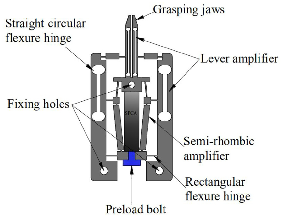
Schematic the diagram of the piezo-driven microgripper.
In order to further improve the gripping stroke and obtain larger output displacement, a three-stage amplifier is designed, including a semi-rhombic amplifier and a double parallelogram lever amplifier. One end of SPCA is fixed with the displacement transmission mechanism (DTM) by the preload bolt, and the preload force on SPCA can be adjusted by the bolt. Through the three-stage amplifier, the DTM from the SPCA to the grasping jaws is realized. As the first-stage amplification, the semi-rhombic amplifier is composed of a connecting rod mechanism based on straight flexure hinges, and a parallelogram mechanism is designed as the second-stage amplification connected with the semi-rhombic amplifier by two flexure hinges. In order to obtain a large displacement amplification ratio, a lever amplifier at each side with the gripper is designed as the third-stage amplification connected with the second-stage amplification by two flexure hinges.
Calculation of the angle change relation of hinges
Figure 2 shows the pseudo-rigid-body model of the microgripper. The main dimensions of the corresponding mechanism are shown in Table 1. The left half of the microgripper was selected for analysis,

Pseudo-rigid-body model of microgripper.
Main component dimensions.
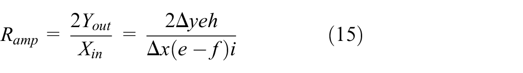
The change angles of angles θ1, θ2, θ3, θ4, θ5, θ6, and θ7 are, respectively,

The deformation of piezoelectric ceramics under the electric field is very small, not more than one-thousandth of its size, so the deformation of the displacement amplification mechanism is very small, and the angular deformation is also very small. Therefore,

Output displacement calculations of microgripper
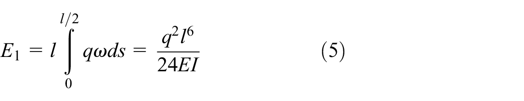
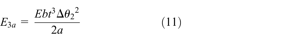
The force acting on the semi-rhombic amplifier is shown in Figure 3. Under the action of uniform distributed force q produced by piezoelectric ceramics, the lower side wall of the semi-rhombic amplifier is bent, which leads to the deformation of the straight flexure hinge and the side length of the semi-rhombic amplifier. According to the principle of conservation of energy, the total energy produced by piezoelectric ceramics is equal to the sum of the energy produced by hinge deformation, the energy produced by the side wall deformation at the lower end of the mechanism and the energy produced by the side-length deformation of the mechanism.

Force diagrams of parallelogram displacement amplifier.
Bending deformation energy of side wall
According to Nie and Meng, 36 the deflection of side wall of piezoelectric ceramics after electrification is as follows

In formula (3), E is the elastic modulus of material, I is the moment of inertia, l is the side wall width of piezoelectric ceramics, and s is the distance from any point on the side wall to the end point. The lateral wall angle is

Side wall deformation energy is
Deformation energy of straight hinges
Figure 4 shows the structural diagram of rectangular flexure hinge. According to Hu and Zhang, 37 the tensile stiffness of rectangular flexure hinge is as follows


Structure and deformation of rectangular flexure hinge.
Bending stiffness

In formulas (6) and (7), m is the length of rectangular flexure hinge.
According to Feng and Song, 38 the tensile deformation energy of rectangular flexure hinge is as follows

In formula (8),
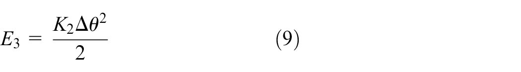
In formula (9), A is the angle of hinge change. Therefore, the bending deformation energy of the upper and lower rectangular flexure hinge is

Deformation energy of side length of a semi-rhombic amplifier
Figure 5 shows the side-length structure diagram of the semi-rhombus amplifier.

Structure and deformation of edge length.
Under the action of piezoelectric ceramic force, the displacement of edge length
Under the action of force, the deformation energy produced by the side length can be as follows
According to the principle of conservation of energy, the output energy of piezoelectric ceramics is equal to the deformation energy of the mechanism
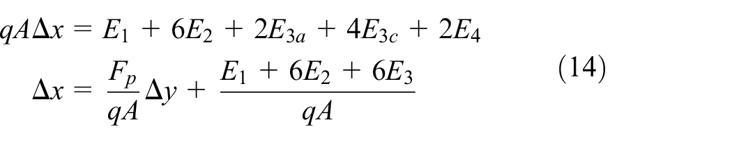
Therefore, the theoretical amplification ratio of the microgripper is
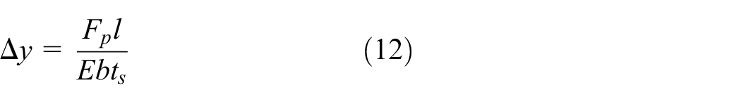
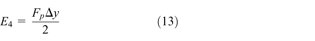
Output force calculations of microgripper
The structure analysis of the microgripper is shown in Figure 6. Under the action of piezoelectric ceramics, the total energy produced by the microgripper is converted into the sum of the total energy produced by the hinge deformation and the output energy.

Structure analysis diagrams of microgripper.
Deformation energy of straight circular flexure hinges
Figure 7 shows the structure of a straight circular flexure hinges. The microgripper only produces bending deformation energy during deformation. According to Tang and Li, 39 the bending stiffness of the straight circular flexure hinge is as follows

Structure and deformation of flexible rigid circular hinge.
In formula (16),
The bending deformation energy of straight circular flexure hinges is as follows

Bending deformation energy of straight circular flexure hinges at

Bending deformation energy of straight circular flexure hinges at

Deformation energy of straight flexible hinges
According to formulas (8) and (9), it can be seen that the bending deformation of the straight flexure hinge at point a only occurs, and the bending deformation energy of the straight flexure hinge at point a

The stretching and bending deformations occur simultaneously at position

The stretching deformations occur at position c, and the deformational energy of the straight flexure hinge at position c is as follows

The stretching and bending deformations occur simultaneously at position

Compression and bending deformations occur simultaneously at point f. Deformation energy of straight flexible hinges at point f is as follows

Compression and bending deformations occur simultaneously at point

According to the conservation of energy, the output energy of piezoelectric ceramics is equal to the sum of the deformation energy of the hinge and the work done by the grasping jaws

Finite element analysis
Structural parameter optimization of microgripper
Using finite element analysis (FEA) software to optimize the structure size of microgripper. As shown in Figure 6, the performance of the microgripper is mainly determined by the structural size of the hinge. Based on the ANSYS software response surface method, the optimal geometric parameters of the microgripper are obtained, and the optimal performance is achieved. The optimized size is shown in Table 2:
Objective: maximum output displacement.
Related parameters: a, b1, c1, d, f, g, e, h, i.
Subject to:
Constraint equations: Parameter range: 3.0 mm ≤ al ≤ 4.0 mm, 0.2 mm ≤ aw ≤ 0.4 mm, 0.4 mm ≤ b1l ≤ 0.5 mm, 0.2 mm ≤ b1w ≤ 0.4 mm, 1.8 mm ≤ c1l ≤ 2.5 mm, 0.2 mm ≤ c1w ≤ 0.3 mm, 4.5 mm ≤ dl ≤ 4.8 mm, 0.2 mm ≤ dw ≤ 0.4 mm, 1.2 mm ≤ fl ≤ 1.8 mm, 0.2 mm ≤ fw ≤ 0.4 mm, 1.5 mm ≤ gl ≤ 2.5 mm, 0.2 mm ≤ gw ≤ 0.4 mm, 1.0 mm ≤ e ≤ 1.5 mm.
Dimension optimization tabled of structural parameters.
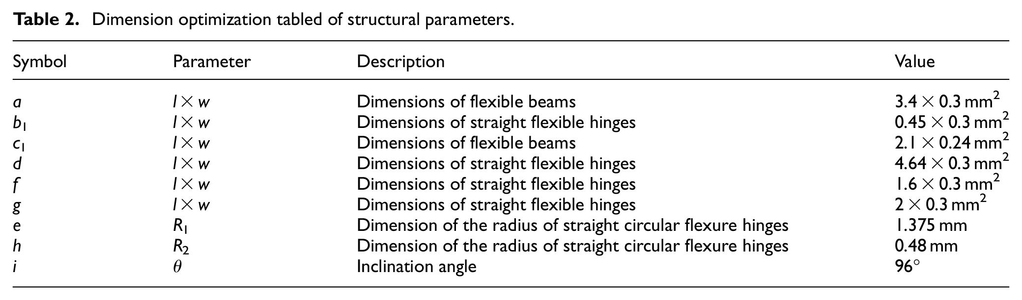
The optimal geometric parameters of the micro clamp can be obtained by looking at the trade-off diagram, and achieve the optimal performance. The optimized size is shown in Table 2.
Performance analysis of microgripper
The design parameters are given as follows:
The microgripper material and micro-parts include 7075 aluminum alloy, a modulus of elasticity E = 71 GPa, a Poisson’s ratio ν = 0.33, a yield strength σ = 455 MPa, and a density ρ = 2810 kg/m3.
The thickness of the microgripper is 5 mm.
Figure 8(a) and (b) shows the displacement and strain nephograms of the microgripper when the part is not gripped under the input displacement of 20 μm.

FEA analysis diagram of microgripper: (a) displacement nephogram of microgripper, (b) stress nephogram of microgripper, and (c) the relation between input force and clamping force of grasping jaws.
Figure 8(a) shows the displacement nephograms of the microgripper. It can be clearly seen that in the closing process, the left and right jaws of the microgripper are gripped in parallel, which effectively avoids the parasitic displacement and the maximum output tip displacement of a single jaw is 245.13 μm and achieves a displacement amplification of 24.513 times; Figure 8(b) shows the strain nephograms of the microgripper. It can be seen from the figure that the maximum stress is 207.89 MPa, which is less than the yield strength of the material and the product can be used safely.
Figure 8(c) shows the relationship between input force of SPCA and gripping force of grasping jaws when using FEA to analyze the micro-axes of 500, 400, and 300 μm, respectively. It can be seen from the figure that there is a linear relationship between the input force and the gripping force, which shows that the performance of the microgripper is stable, and a smooth transition is achieved from the grasping jaws closure to the grasping of the micro-axis. The maximum stress corresponding to the three micro-axes of different sizes are 101.34, 101.74, and 97.902 MPa, all of which are far less than the yield strength of the material. The output force of the grasping jaw is 7.3 N under the input force of 78.6 N when the micro-axis is gripped at 500 μm.
Experiment
Physical model of microgripper
The physical model of the microgripper is shown in Figure 9. The material used for the microgripper is 7075-T6 (SN) of aluminum alloy. The microgripper is processed by wire electrical discharge machining (WEDM) machine tool with slow-walking. After processing, the microgripper is drilled and polished. The experimental equipment includes HPV-1C 0300 A0300 piezoelectric ceramic driving a power supply, micro-sodium positioning worktable, PZT (SZBS150/5×5/20, open-loop travel 20 μm; Suzhou Mat, Inc.) driving micro-positioning stage, high-resolution capacitive displacement sensor (MA-0.5; BJZD company), a data acquisition card (PCI-6221; NI company), and micro-tension pressure sensor (JLBS-MD-150N; BBJN company). 24 V DC regulated power supply WP100-D-G, host computer and display matched with the sensor signal amplifier BSQ-2, and 24 V DC regulated power supply WP100-D-G. In order to eliminate the external interference as much as possible, all the devices are installed on the high-performance vibration isolation platform.
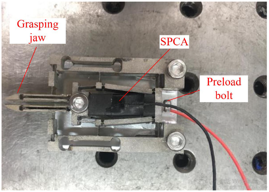
Physical model of microgripper.
Experimental verification
Analysis of microgripper performance
In order to further test the performance of the microgripper, a series of experiments were carried out to verify the performance of the microgripper. The experimental device is shown in Figure 10. Figure 11(a) shows a theoretical working diagram of this device, and Figure 11(b) shows a photographic diagram of the actual components of the experimental device.

Experimental setup of the microgripper.

Working principle diagramed of the experimental device: (a) functional block diagram, and (b) actual working diagram.
Figure 12 shows the relationship between the input displacement and the piezoelectric actuator driving voltage from 0 to 150 V. The results confirm the nonlinear characteristics and hysteresis of the piezoelectric material. When the input voltage is 150 V, the maximum output displacement is 22.08 μm, which is larger than the nominal output displacement of SPCA. Under the open-loop control condition, when the driving voltage is 20 V, the output displacement difference of expansion and contraction reaches the maximum value, which is 2.74 μm.

Input displacement versus the drive voltage.
Figure 13 shows the relationship between the input force and the driving voltage of piezoelectric ceramic actuator. When the input voltage is 150 V, the maximum input force is 84.9 N.

Input force versus the drive voltage.
However, the nonlinearity of the piezoelectric material does not affect the linear relationship between the input and output of the microgripper. Figure 14 shows the relationship between the input displacement of the microgripper and the tip displacement of grasping jaws, and the relationship between the input displacement of the microgripper and the input force of the piezoelectric ceramic actuator. From the graph, it can be seen that the input displacement of the microgripper is linearly related to the tip displacement of grasping jaws, which shows that the microgripper has stable performance.

The relationship between input displacement of microgripper and tip displacement of a single jaw, and the relationship between input displacement of microgripper and input force of piezoelectric ceramic actuator.
The theoretical amplification factor is 26.268 times, the FEA simulation amplification factor is 24.513 times, and the experimental magnification factor is 24 times. The error between the experiment and the FEA simulation is 1.89%, while the error between the experiment and the theoretical calculation is 8.63%. The three displacement amplification ratios by different methods are very close, which has proved the correctness of the theoretical calculation. There is a certain degree of deviation between the physical model and the theoretical modeling due to the machining error, which results in the error between the experiment value, FEA simulation value, and the theoretical calculation value. The theoretical calculation is based on the idea of pseudo rigid body model, which only considers the deformation of the flexure hinges and regards the other parts of the flexure hinge as rigid bodies. Actually, there is indeed deformation in other parts of flexure hinge. However, the multi-stage amplifier can restrain the single machine amplifier; that is why the theoretical calculation value is larger than the FEA simulation value and the experiment value. It is inevitable that there exists accuracy error in the process of microgripper machining, the measurement error in the process of experiment, and the influence of equipment vibration and noise; that is why the experiment value is smaller than the FEA simulation value.
In order to verify the applicability of the microgripper, we performed several grasping experiments. Figure 15 shows a photograph of the microgripper grasping a metal plate, a wire, and a plastic plate, respectively. The results show that the microgripper has the characteristics of parallel gripping, large grasping range and self-adaptability to different shapes of grasping objects, and can successfully grip micro-objects. Figure 16 shows the microgripper parallel approaching and grasping 250 μm metal ball.

Grasping manipulation for different shaped and sized micro-objects (from left to right): (a) 300 μm metal plate,(b) 250 μm metal wire, and (c) 120 μm plastic plate.

(a–b) approaching and (c) grasping the micro-object.
Performance comparison
The magnification of our microgripper versus similar devices12–18 are shown in Table 3. The magnification of the microgripper designed in this article reached 24 times, which is greater than other microgrippers.
Comparison of the parameters with similar microgrippers.

Conclusion
In this article, a new piezoelectric microgripper with compact structure, parallel gripping, high magnification, and miniaturization is designed. The theoretical amplification ratio and the relationship between input and output variables are obtained by theoretical calculation. The performance of the microgripper is obtained by FEA. With a 500-μm micro-axis, the gripping force was 7.3 N at a 78.6 N input force, and the corresponding stress is far less than the yield strength of the material. The prototype is manufactured by the WEDM machine with slow-moving wire. After processing, drilling and polishing are carried out. The experimental results show that the actual amplification ratio of the microgripper is 24. Input and output displacement, input displacement and output force are both linear and stable. When the input voltage is 150 V, the output displacement of the grasping jaws reach the maximum value, which is the same as the expected result. The maximum output displacement is 530 μm. The jaws have successfully grasped micro-objects of different shapes and sizes. The design of the microgripper provides a useful reference for the research of precision instruments.
Footnotes
Handling Editor: James Baldwin
Declaration of conflicting interests
The author(s) declared no potential conflicts of interest with respect to the research, authorship, and/or publication of this article.
Funding
The author(s) disclosed receipt of the following financial support for the research, authorship, and/or publication of this article: This article was supported by the Liaoning Provincial Education Department (L2017LQN024).