
Abstract
It is important to obtain optimal grasping performance of a parallel hybrid hand in order to reduce the grasping impact force and power loss, to avoid the damage of object or human body during grasping operation or rescue missions. In this article, the coordinated grasping kinematics of the multi-fingers and the optimization of grasping force for a parallel hybrid hand are studied and analyzed systematically. First, the coordinated grasping condition is analyzed, and the formulae are derived for solving the displacement, the velocity, and the acceleration of the contact points between the object and the multi-fingertips of the parallel hybrid hand. Second, the formulae are derived for solving the contact forces at the contact points. Third, the frictional constraints between the multi-fingers and the object are analyzed during stable grasping, and the formulae are derived for solving the optimum contact forces. Finally, an analytic numerical example is given, the analytic solutions of the coordinated grasping kinematics and optimum contact forces are solved and verified by simulation solutions.
Introduction
A parallel hybrid hand is a parallel manipulator (PM) equipped with several fingers on the moving platform. It has played an important role in application of forging operation, rescue missions, manufacturing and fixture of parallel machine tool, Computer Testing (CT)-guided surgery, and micro-operation of biomedicine and assembly cells. 1 –8 In this aspect, Zhang and Gao 9 designed a biologically inspired 4 universal joint, prismatic joint and spherical joint (4UPS) + PU hybrid PM for mine rescue robot and studied its kinematics and structure optimization. Ramadan and Inoue 10 developed architecture of a hybrid two-fingered micro–nano manipulator hand. Liu et al. 11 proposed a hybrid robot for CT-guided surgery. Wang et al. 12 designed a reconfigurable robot for search/rescue. The fingers are key tools of the forging operator, rescue robots, and mediation robots. In this aspect, Mir-Nasiri 13 designed a four-axis parallel robotic arm for assembly operations. Yan et al. 14 established a coordinated kinematic modeling of gripper of the manipulator for heavy-duty manipulators in an integrated open-die forging center. Nuttall and Klein 15 analyzed mechanical compliance effects in a gripper with parallel jaws. Zhang et al. 16 classified grasping robotic hands into three categories based on the object connectivity. In various PMs, the 5- and 6-degree of freedom (DoF) PMs with composite spherical joint Sc should be selected as the parallel hybrid hand because the moving platform can provide more room for arranging more fingers and has more DoFs and higher stiffness. In the aspect of PMs with Sc , Zhang 7 synthesized various PMs with different limbs and different Sc . Huang et al. 8 analyzed the structure of a 3/6 Gough-Stewart PM with 3Sc . Ben-Horin and Shoham 17 synthesized a class of PMs with six limbs and several Sc . Lu and Hu studied kinematics and statics of a 5-DoF 4SPS + spherical joint-active prismatic joint-revolute joint (SPR) PM with 2Sc . 18 In aspect of coordinated grasping kinematics and the optimization of grasping force of robot hand, Lippiello et al. proposed a grasping force optimization algorithm for multiarm robots with multi-fingered hands 19 and studied multi-fingered grasp synthesis based on the object dynamic properties. 20 Roa and Suárez 21 solved the independent contact regions for grasping 3-D objects. Qin et al. 22 optimized the grasping force of robotic multi-fingered hands based on the frictional constraints. Watanabe and Yoshikawa 23 studied grasping optimization using a required external force set. Xia et al. 24 optimized grasping force of multi-fingered robotic hands using a recurrent neural network. Zheng and Qian 25 studied weaknesses existing in optimal grasp planning of robot hand. Song et al. 26 proposed the dual-fingered stable grasping control for an optimal force angle. In fact, it is difficulty to manufacture Sc . Therefore, a 5-DoF PM with two equivalent composite universal joints Ue is proposed for constructing a parallel hybrid hand equipped with three fingers in this article. Up to now, the studies on the coordinated grasping kinematics and the optimization of grasping force of the parallel hybrid hand have not been found. Since this parallel hybrid hand is designed for high-speed and heavy-load coordinative operation or rescue missions, it is significant to obtain optimal grasping performance for the parallel hybrid hand in order to reduce the grasping impact force and power loss and to avoid the damage of object or the injury of human body during grasping and rescue missions. For this reason, this article focuses on the coordinated grasping kinematics of the multi-finger and the optimization of grasping force of a parallel hybrid hand in the light of its applications.
Prototype of hybrid hand and its structural characteristics
A 3-D prototype of the parallel hybrid hand is constructed as grasping different objects, see Figure 1.

A 3-D prototype of parallel hybrid hand as grasping objects.
The parallel hybrid hand is composed of a 5-DoF PM with two equivalent composite universal joints Ue and three 1-DoF finger mechanisms. The 5-DoF PM with 2Ue includes a platform m, a base B, two composite limbs, and an SPR-type active leg r 3. Here, m is a regular triangle Δb 1 b 4 b 3 with three vertices, three sides sm , and a central point o; B is an equilateral pentagon B 1 B 2 B 3 B 4 B 5 with five vertices, five sides sB , and a central point O. Each of the composite limbs includes an equivalent composite universal joint Ue and two SPR-type active limbs. Ue is composed of a beam gi (i = 1, 2) with two collinear revolute joints and a universal joint U with two cross revolute joints Rvi and Rhi . The middle of g 1 is connected with m by U joint at point bj (j = 1, 2). Two ends of g 1 are connected with the upper ends of the jth SPR active leg lj (j = 1, 2) by revolute joints Rj (j = 1, 2) at aj . The middle of g 2 is connected with m by U joint at point bj (j = 4, 5). Two ends of g 2 are connected with the upper ends of the jth SPR active leg lj (j = 4, 5) by revolute joints Rj (j = 4, 5) at aj . The lower end of lj (j = 1, 2, 4, 5) is connected with B by the spherical joint S at Bj . r 3 connects B with m by a spherical joint S at B 3, an active prismatic joint P and revolute joint R 3 at b 3, see Figure 2.
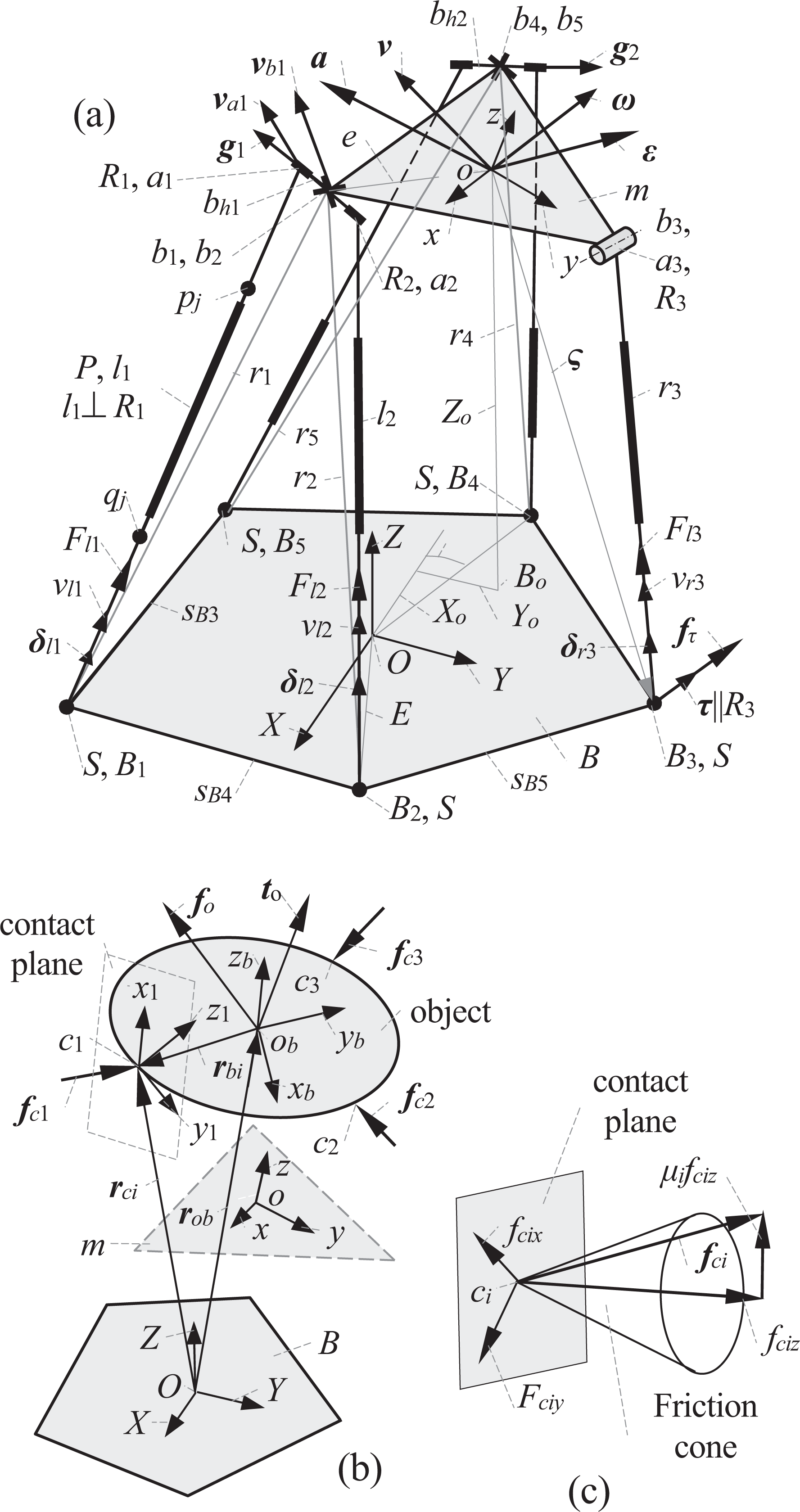
Kinematics model and grasping force situation of parallel hybrid hand. (a) The kinematics/statics model of 5-DoF PM with 2Ue , (b) the kinematics/statics coordinate system object, and (c) contact force model of fingertip and object. DoF: degree of freedom; PM: parallel manipulator.
Let ⊥, ||, and | be the perpendicular, parallel, and coinciding constraints. Let {si } be a coordinate frame oi -xiyizi of the ith finger mechanism, {m} be a coordinate frame o-xyz fixed on m at o, and {B} be a coordinate frame O-XYZ fixed on B at O. This PM includes the following geometric conditions {b 1|b 2, b 4| b 5, z⊥m, Rvi ||z, Rhi ⊥Rvi , R 1|R 2, R 4|R 5, Rh 1⊥R 1, Rh 2⊥R 4, Rj ⊥lj , b 1 b 4||x, R 3||x, R 3⊥r 3, ob 3|y, ajbj = b, obj = e, (i = 1, 2; j = 1, 2, 3, 4, 5)}. Each of the finger mechanisms has 1-DoF, and it is formed by a planar four bar mechanism which is composed of a frame, a claw, and an SPR-type active rod Li . The three fingers can coordinately grasp object. The frame is fixed on m at a point oi and distributed uniformly on m at the same circumference.
Coordinated grasping kinematics of parallel hybrid hand
Generally, the object is kept in a static state or moving, and the multi-fingertips are moved toward object during multi-fingertips grasping. Thus, the multi-fingertips apply the impact forces onto the object. Since the relative motion of object and the multi-fingertips must has a large influence on grasping performance, it is necessary to analyze the coordinated grasping kinematics of parallel hybrid hand and object.
Displacement of parallel hybrid hand
The kinematics model and the grasping force situation of the parallel hybrid hand are shown in Figure 2. A vector
Let (Xo
, Yo
, Zo
) be the position components of o in {B}. Let (α, β, λ) be three Euler angles of m in {B} and E be the distance from O to Bi
; (xl
, xm
, xn
, yl
, ym
, yn
, zl
, zm
, zn
) be nine orientation parameters of m. Let ϕ be one of (α, β, γ, φ, 2φ, θ, αi
, βi
, γi
, θi
). Set sϕ
= sinϕ, cϕ
= cosϕ, and tϕ
= tanϕ. The formulae for solving

When given (α, β, γ, Yo , Zo ), lj can be solved from equation (1) and equation (1A) in Appendix 1.
Displacement of the ith fingertip
Let ci
be the ith fingertip. As grasping object by multi-fingers, each of the fingertips contacts with object at contact point ci
without slide. Therefore, it is necessary to analyze the kinematics of the ith finger mechanism wi
(i = 1, 2, 3). The kinematics model of wi
(i = 1, 2, 3) and their distribution on m are shown in Figure 3. In {si
}, (xi
||z, yi
|ooi
) are satisfied. Let Li
be an extension of the active leg of wi
, and Wki
(k = 1, 2, 3, 4) be the key points on wi
. Let d
1 and d
2 be the distances from oi
to W
1i
and W
2i
, respectively. Let d, d
3, and d
4 be the distances from W
1i
to ci
, W
3i
, and W
4i
, respectively. Let d
5 be the distance from W
2i
to W
3i
and d
6 be the distance from W
4i
to ci
. Let αi
be the angle between d
3 and d
4, βi
be the angle between d
4 and d, γi
be the angle between d
1 and d
3, and θi
be the angle between xi
and d. Let
m
si

Finger mechanism and its coordinate system.
Velocity and acceleration of the ith fingertip and parallel hybrid hand
Let

The kinematic formulae between

Here,
Let

Here,
Let
Let
Let

From equations (3) and (5), it leads to

When (


Let
A relation between
Analysis of contact force
Basic concept and condition of grasping
When grasping object or operating using multi-finger, a kinematic model is depended material and outline of grasped object. In this case, the fingertips apply grasped constraint forces onto object to balance the external workloads applied on object, and a statics balance of grasped object is kept. Thus, the sum of all force vectors should be 0. 22 However, as the multi-fingers apply very large grasping forces onto the object or human body and also satisfy the statics balance condition of multi-finger grasping object, the multi-fingers may damage the object or injury human body. Therefore, it is necessary to establish a statics model for solving reasonable contact force of the parallel hybrid hand for avoiding damage of the object or injury of human body.
Suppose that the contact between the multi-fingertips and the object is a friction contact without slide. When a arbitrarily workload is applied on object, if the contact force exerted onto object by fingertip is within a cone angle of friction, then the frictional force has not reached the maximum statics frictional force, and slide does not occur. 19 –22 In this case, contact forces resist the arbitrarily workload applied on object. This grasping is a force closed grasping. 29,30 In order to complete grasping and operating task using the multi-fingers, the arbitrarily workload applied on object must be balanced by the contact forces between multi-fingertip and object. It is defined as a multi-fingertip stability balanced condition. Based on this condition, the contact force applied on object can be solved as given arbitrarily workload on object.
In a multi-finger grasping system, let ci
(i = 1, 2, 3) be the three contact points between the fingertips and the object. Let {ci
} be a coordinate system (ci
-xiyizi
) attached onto ci
. Here, xi
and yi
are located in tangent plane of ci
, and zi
is normal of plane which includes ci
(i = 1, 2, 3). Let
ci

Based on the stability balanced condition, the frictional force between the multi-fingertip and the object must be less than the maximum statics friction force. Thus, a friction constraint equation is described as follows

Here, μi is the friction coefficient at point ci .
Let
B
ci

When

Here,
Substituting equation (13) into equation (14), a balance equation for the generalized forces applied to the object can be represented as follows

Here,
In order to balance object and obtain stability of grasping, a statics equation between the general external workload

Thus,
c
Since
Basic theory of equations set with generalized inverse matrix
Let

An equation set

Here,

Here, bij
(i = 1,2,…, m; j = 1, 2,…, n-m) is each simplified item of
Since
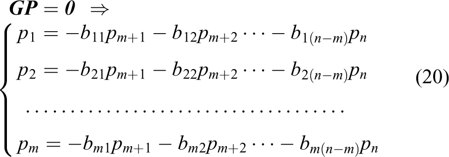
Here, pj (j = m+1,…, n) is an arbitrarily constant.
Thus, a general solution of equation set

A simple formula of general solution of

Here,
When replacing vector

Here, di
(i = 1, 2,…, m) are the simplified item of [
Since (
Substituting equation (23) into

The solutions
Here,

Here, λ is an arbitrarily constant for optimizing workload.
Since
Solving contact force
When

Each of items in

Here, p 7, p 8, and p 9 are three arbitrarily constants.
Replacing

Here, λ is an arbitrarily constant for optimizing workload.
c

Here,
c
c


In equation (32), the magnitude and orientation of
ci
If the contact forces
ci

Substituting
ci

Next, an equivalent constraint equation is derived from equation (34) as follows
In fact, equation (35) is a constraint condition of solving contact force in the light of friction cone constraint of multi-finger grasping system. Thus, the challenging issue of solving grasping force is transformed into to determine whether constraint condition (equation (35)) is satisfied. If constraint condition (equation (35)) is satisfied, then grasping is stable. After that, the optimum grasping force can be solved.
Optimization of contact force
When the contact force of multi-fingers applied onto object becomes too large, the finger mechanism or the parallel mechanism may be damaged. At the same time, more power is required for the unnecessary larger input active forces of finger mechanism and parallel mechanism. Therefore, the contact force of multi-fingers applied onto object must be limited within reasonable value. Thus, an optimum object is that the contact force of the multi-fingers applied onto the object should be the lowest when the stable grasping condition is satisfied.
The condition of internal force
c
Suppose that the constant η is an objective function, equation (35) is a constrained boundary condition for constructing optimum model. An optimum objective function is represented as follows

Each of elements
Substituting
The general contact force
c
The contact force
ci

After expending equation (39), it leads to

Substituting
ci


As λi satisfying equation (36), λi and λ are solved from equation (41) as follows

Next, the optimum grasping force
c

After that, the optimum statics formulae of parallel hybrid hand can be derived based on the principle of virtual work. 1 Finally, the optimum active forces of multi-finger mechanism and the optimum active forces of PM can be solved based on the derived optimum statics formulae of parallel hybrid hand.
Solved example and verification
The geometric parameters and the input kinematics of PM and the fingers are given, see Table 1.
Given pose parameters, input velocity of PM, geometric parameters of finger mechanism, and the workloads exerted on fingers.
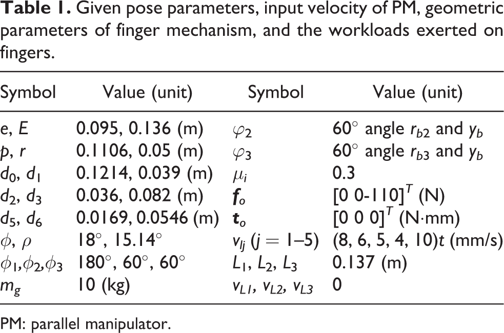
PM: parallel manipulator.
Based on the parameters in Table 1 and relative analytic formulae, the positions of contact point ci (i = 1, 2, 3) in {B} are solved, see Figure 4(a). The velocities vli of li in PM are solved and varied within 0–0.1 s, see Figure 4(b). The accelerations ali of li in PM are solved and varied largely within 0–0.1 s, see Figure 4(b) and (c).

Analytical kinematics solutions of contact point in {B} and lj of PM. PM: parallel manipulator.
Let k be the number of iteration in optimum history. Based on analytical formulae in “Optimization of contact force” section, the optimum history of the contact force

Optimum history of contact force versus iterations k = 11 and optimum results of contact forces.
Let fciz
be the normal component of the contact force
fciz
(i = 1, 2, 3) are reduced as increasing k.
fciz
satisfy constraint condition as k = 4. As increasing k, fciz
are reduced largely until k = 11. As k = 11, optimum values of fciz
are reached.
The optimum results of three components of contact force
When the optimum results of three components of contact force
By utilizing Solidwork, the positions of the contact point in {B} are obtained, see Figure 6(a). The velocities vli and accelerations ali of li (i = 1, 2, 3) in PM are obtained, see Figure 6(b) and (c). The contact forces before optimization are obtained, see Figure 6(d).

Simulation solutions of kinematics and contact forces of contact point in {B} and lj of PM by utilizing Solidwork. PM: parallel manipulator.
In fact, in the whole grasping processes, the multi-fingertip move, contact, and grape the object, the object is subjected a rigid collision force and is moved from static state to the moving state of the multi-finger. In order to simulate the whole grasping processes, a translational actuator is added onto the active limb of finger mechanism, and set vlj = 0, thus the extension of linear actuator is kept as constant. Thus, it ensures that the fingertip is the same as contact point. Set object is cylinder with radius 0.05 m. The three fingertips ci (i = 1, 2, 3) are distributed uniformly on the same circumference of the cylinder object and locate the same plane.
The absolute errors between Figures 4(a) and 6(a) are shown in Figure 7(a). The absolute errors between Figures 4(b) and (c) and 6(b) and (c) are shown in Figure 7(b) and (c). The absolute differences between the optimization solutions in Figure 5(d) and before optimization solutions in Figure 6(d) are shown in Figure 7(d).
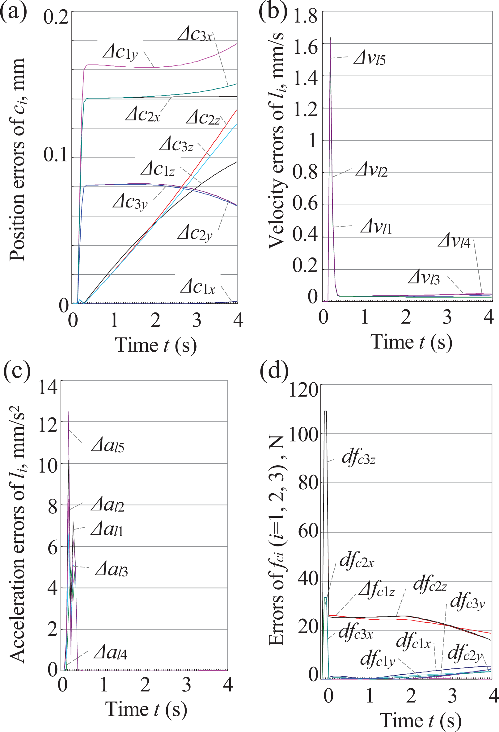
Absolute errors between analytic solutions and simulation solutions of kinematics and contact forces.
It is known from Figure 7(a)to (c) that the analytical solutions are coincident with the simulation solutions. It is known from Figure 7(d) that optimization solutions of the contact forces are less than that before optimization solutions. Therefore, the derived formulae in this article are correct.
Conclusions
A proposed parallel hybrid hand is composed of a 5-DoF PM with two equivalent composite universal joints and three 1-DoF finger mechanisms.
The coordinated grasping kinematics model of the multi-finger is established, and the formulae are derived for solving the displacement, the velocity, and the acceleration of the contact points of the object with the multi-fingertip of the parallel hybrid hand.
The optimum contact force model of the parallel hybrid hand is established, and the formulae for solving the optimum contact forces are derived.
The solved input velocity of parallel hybrid hand is varied within 0–0.1 s, and the input acceleration of parallel hybrid hand is varied largely within 0–0.1 s. The analytic solutions of the coordinated grasping kinematics and the optimum contact forces are verified by simulation solutions.
When the optimum results of contact force are reached, the grasping impact force and power loss of parallel hybrid hand can be reduced and the damage of object or the injury of human body can be avoided.
This parallel hybrid hand has potential applications for forging operation, rescue missions, industry pipe inspection, manufacturing and fixture of parallel machine tool, CT-guided surgery, health recover and training of human neck or waist, and micro–operation of biomedicine and assembly cells. The theoretical formulae and the solved results of the coordinated grasping kinematics and the optimum contact forces provide a foundation for its structure optimization, control, manufacturing, and applications.
Footnotes
Acknowledgements
The authors would like to thank (1) project (E2016203379) supported by Natural Science Foundation of Hebei, (2) project (51175447) supported by National Natural Science Foundation of China (NSFC), and (3) project (JX2014-02) supported by Yanshan University.
Declaration of conflicting interests
The author(s) declared no potential conflicts of interest with respect to the research, authorship, and/or publication of this article.
Funding
The author(s) disclosed receipt of the following financial support for the research, authorship and/or publication of this article: The author(s) received financial support for the research, project (E2016203379) supported by Natural Science Foundation of Hebei, (2) project (51175447) supported by National Natural Science Foundation of China (NSFC), and (3) project (JX2014-02) supported by Yanshan University.
Appendix 1
Appendix 2
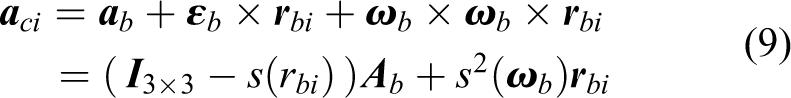
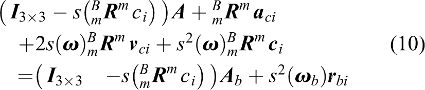
The position vectors of ci (i = 1, 2, 3) in {si }, {m}, and {B} and the position vectors oi in {m} are derived by Murray et al. 33 and are represented as follows
Let
Let