
Abstract
Cancer represents a major threat to human health. Magnetic resonance imaging (MRI) provides superior performance to other imaging-based examination methods in the detection of tumors and offers distinct advantages in biopsy and seed implantation. However, because of the MRI environment, the material requirements for actuating devices for the medical robots used in MRI are incredibly demanding. This paper describes a novel double tendon-sheath transmission device for use in MRI applications. LeBus grooves are used in the original transmission wheels, thus enabling the system to realize long-distance and large-stroke transmission with improved accuracy. The friction model of the transmission system and the transmission characteristics model of the novel tendon-sheath structure are then established. To address the problem that tension sensors cannot be installed in large-stroke transmission systems, a three-point force measurement method is used to measure and set an appropriate preload in the novel tendon-sheath transmission system. Additionally, experiments are conducted to verify the accuracy of the theoretical model and multiple groups of tests are performed to explore the transmission characteristics. Finally, the novel tendon-sheath transmission system is compensated to improve its accuracy and the experimental results acquired after compensation show that the system satisfies the design requirements.
Keywords
Introduction
According to the global cancer statistics for 2018, 1 there are currently an estimated 18.19 million new cancer cases and 9.6 million cancer deaths per year. Cancer is a serious threat to human health and affects people’s lives in both developed and developing countries. Magnetic resonance imaging (MRI) is widely used when performing biopsies and therapeutic surgery because it offers highly accurate cancer detection,2,3 provides high-definition and high-resolution images, and does not subject patients to radiation. The medical robots used in MRI are attracting increasing attention from the international medical community4–6 and from scientific researchers in recent years because of advantages that include high efficiency and minimally invasive performance. However, MRI uses a strong magnetic field. There are thus strict requirements for the selection of suitable materials for these robots and their drive systems.7–9 In addition, there is an urgent need for a robot driving method that is suitable for use in the nuclear magnetic environment because such a method would allow robots to assist in operations without affecting the MRI results.
The tendon-sheath concept has been widely used in medical and other types of robots10–13 because of its high transmission precision, light weight, smooth transmission, flexibility, and small size. Kaneko et al.14,15 studied the transmission characteristics of a simple tendon-sheath model for finger joint control. They reported an elastic hysteresis phenomenon in the transmission process and observed a change in the transmission stiffness when the transmission direction changed. Their model was limited to a constant transmission angle and constant preload, and the torque model and the hysteresis characteristics of the transmission device were verified from both experimental and simulation perspectives. Palli et al. 16 proposed both static and dynamic models of tendon-sheath actuation systems. They also introduced a new viscoelastic model in which polymeric fibers were used as tendon materials for a robotic hand. A simple control strategy was proposed to compensate for nonlinear effects and a complex LuGre-like dynamic friction model was used to improve the controller reliability. Agrawal et al.17,18 proposed a set of continuous time-domain partial differential equations for a tendon-sheath structure with an arbitrary curvature and initial tension distribution. They also considered the effects of the MRI environment and time-varying nonlinear viscoelastic behavior. Their model can effectively analyze the backlash from motion, the relaxation phenomenon of the system, and the transmission tension between the two cables.
Phee et al.19–21 studied control of the precise positioning and the force feedback from robotic arms used in natural orifice transluminal endoscopic surgery. Nonlinear adaptive control algorithms and real-time enhancements for tracking were designed to improve the performance of the cable-conduit mechanisms. They also developed a motion control device, a telesurgical workstation and a slave manipulator. Schiele et al.22,23 investigated a new type of tendon-sheath actuator to perform force-reflection to a wearable exoskeleton. They proposed a hardware prototype in which springs ensured the constant preloading associated with the packaging angles. The transmission characteristics of the tendon-sheath system between the actuator and the robot joint were also analyzed.
Jiang et al.24,25 designed and analyzed MRI-compatible surgical robots for breast puncture and prostate needle insertion operations. In their approach, the tendon-sheath systems were used for power transmission over comparatively long distances. Wang et al.26,27 established a transmission model for a double tendon-sheath structure under arbitrary load conditions and analyzed many non-ideal and nonlinear tendon-sheath transmission problems. They also built an experimental tendon-sheath platform and applied friction and control compensation measures to the tendon-sheath transmission.
Currently, the joints of the manipulators of medical robots, and particularly surgical robots, are often driven using tendon-sheath systems. The transmission wheels of these tendon-sheath systems are usually made from metal and are primarily designed for single-slot and single-layer arrangements. The range of possible transmission angles is typically small. However, MRI-compatible interventional surgical robots require a transmission system that can be driven over a wide range of angles and over long distances within a limited space. In addition, the commonly used transmission wheels with thread grooves often suffer from the phenomena of empty ropes and stacked ropes when the wheels are winding; in the former case, the tendon is wound in multiple grooves for a single lap, while in the latter case, the tendon is wound for multiple laps in one groove. Regardless of whether these phenomena occur in the first layer or in multiple layers, this will affect the winding accuracy.
Based on previous studies, this paper describes a new type of tendon-sheath transmission device that combines long-distance power transmission with nuclear magnetic compatibility. LeBus grooves are used in the transmission wheels to solve the problem of random winding during tendon-sheath multi-layer transmission; this allows the transmission accuracy to be further improved. The motor can be located away from the MRI source to avoid affecting the imaging, and power can be transmitted to the robot on the nuclear magnetic resonance apparatus via the tendon-sheath system. In this way, the problem of nuclear magnetic incompatibility can be solved and the service life of the tendon-sheath device can be extended.
Design and friction study of double tendon-sheath transmission wheels with LeBus grooves
The proposed tendon-sheath system uses nonmetallic materials to meet the requirements of the nuclear magnetic environment. Figure 1 illustrates use of the proposed system in a nuclear magnetic environment. Long-distance and wide-range transmission can be realized and the sizes of the transmission wheels are minimized to satisfy force demands (including space constraints). Therefore, the transmission wheels arrangement will use a multi-layer winding method. However, there will inevitably be contact between the upper and lower layers of the tendon or between adjacent tendons that are wound within the same layer. Friction between adjacent tendons caused by extrusion means that the contact point of the tendon is subjected to a sliding friction force during movement. Therefore, the stress characteristics of the novel tendon-sheath transmission system must be analyzed.

Application of a new type of tendon-sheath transmission device in an MRI environment.
The tendon used in the proposed system is composed of eight slender, flexible strands. Because a single flexible tendon is relatively small in size, it is necessary to determine the areas where damage to the device could occur and to characterize the fatigue wear of the tendon. However, changes in the infinitesimal displacement relative to the size of the overall flexible tendon are of low significance. Therefore, to simplify the calculations and obtain analytical data about the macroscopic stresses, the tendon is considered as a cylinder here. The transmission winding mode of the double tendon-sheath is illustrated in Figure 2. The driving wheel uses left-hand threads while the follower wheel uses right-hand threads, so the transmission directions of the wheels remain consistent. In the initial state, the thread grooves on side B of the driving wheel and the thread grooves on side A of the follower wheel are wound all over the wheel and these windings cover the same n layers (where n is a positive integer). The thread grooves on side A of the driving wheel and those on side B of the follower wheel are then unwound. Arrows indicate the rotation of the transmission wheels, and the two transmission wheels are oriented parallel to one another.

Schematic diagram of double tendon-sheath and helical angle distribution of the transmission winding mode.
During the winding process, the axis of the tendon changes from the fleet angle (i.e., the angle between the center line of the tendon and the plane perpendicular to the axis of the transmission wheel) to the helical angle of the transmission wheel. To enable calculation of the variations in the bending angle and the friction force of the tendon during the process of multi-layer winding of a double broken-line transmission wheel, the angle that represents the transformation of the tendon from the fleet angle γ to the helical angle
To indicate the frictional force of the multi-layer winding of the tendon, the LeBus grooves on the right-hand side of the driving wheel are used as an example. As shown in Figure 3, the spatial rectangular coordinate system of the transmission wheel denoted by O-XYZ is established in a relatively static state. The origin O of the coordinate system is located at the center of the transmission wheel. The XOY plane lies perpendicular to the axis of the driving wheel. The right-hand side of the driving wheel indicates the positive direction of the z-axis.

Schematic diagram showing the spatial rectangular coordinate system and the cylindrical coordinate system in the transmission wheel.
To describe the position and calculate the friction force of the tendon on the transmission wheels, a corresponding cylindrical coordinate system is established based on the rectangular O-XYZ coordinates of the transmission wheel. X, Y, and Z represent the coordinate values of the points on the tendon in the spatial rectangular coordinate system and

The starting point of the tendon winding on the driving wheel is

Figure 3 shows that when the transmission wheel rotates by 360°, it will experience two straight grooves and double broken-line grooves, where the combined rotation angle of a straight groove and a broken-line groove is 180°. Let the lengths of the straight grooves and the broken-line grooves of the transmission wheel when rotating by 360° in the direction perpendicular to the axis of the driving wheel be ls and lb, respectively. The angle at which the tendon winds around each straight groove is αs, and the angle at which the tendon winds around each broken groove is αb.
These two angles can be expressed as:

Therefore, zp can be expressed as follows:

where Ps is the pitch of one rotation of the transmission wheel,
As Figure 2 shows, the distance between the baffle on which the sheath is placed and the tendon on the driving wheel is Lc.
Assuming that the tendon is in an ideal condition in terms of its winding and tightening on the driving wheel, when the tendon is located within the

When the tendon is located in the range from O–
The friction force of the tendon on the transmission wheel is related to both the fleet angle γ and the helical angle

and the friction force of the first layer of the transmission wheel Ff1 can be expressed as:

Therefore, the friction force Ff1 can be expressed as:

As shown in Figure 4, in most areas, the second layer of the tendon is wound systematically in the grooves arranged in the first layer of the tendon and this can be considered to be a triangular arrangement. This arrangement is relatively stable and thus the second layer of the tendon can be regarded as being supported by the bottom layer only. The same is true for multi-layer windings of the tendon and there is no trend for mutual movement. At this point, the stress of the tendon can be expressed as follows:

where Np is the extrusion force between the two layers of the tendons and is given by:

and ϕ represents the angle between the winding force of the transmission wheel and the direction normal to the contact surface of the tendon. The geometric relationship between the upper and lower layers of the tendon can be approximated as an equilateral triangle and thus ϕ≈ 30°. The circumferential winding force Fq2 generated by the winding of the tendon in the second layer can be expressed as:

Because the diameter of the tendon is very small relative to the diameter of the transmission wheel, D2 can be approximated as

Because the winding of the tendon during transmission is mostly in triangular form, the friction force of the tendon in layer N*+2 (where N* is a positive integer) can be calculated using equation (13) in the case of winding of multiple layers. It is only necessary to consider the transmission wheel diameter after winding of the tendon based on the diameter of the actual transmission wheel and the diameter of the tendon.
Schematic diagram of stress of the second layer of the tendon on the transmission wheel.
Research on nonlinear transmission characteristics of the double tendon-sheath with LeBus grooves
Unit and unidirectional motion formulas
In the transmission process of the double tendon-sheath system, the elastic elongation deformation of a tendon with no relative motion on the transmission wheel is not taken into account—only the friction between the transmission wheel and the tendon, the friction between the tendon and the sheath, and the elastic elongation deformation of the tendon are considered. The force of the small static element in the double tendon-sheath system is analyzed first. In Figure 5, the following notation is used.

Force balance of a tiny segment of the tendon-sheath system.
The force model of the tendon is shown in Figure 5 and the relational formulas are as follows:

where T is the tension of the tendon, N is the normal force, f is the friction force, μ is the friction coefficient, R is the radius, dθ is the curve angle, dT is the change in tension, and dl is the tendon segment length.
If the coefficient of dynamic friction is equal to the coefficient of static friction, then the following equation can be obtained:

Let

Schematic diagram of tendon-sheath transmission with arbitrary curvature.
Therefore, the tendon of the ith segment can be represented by:

where

For a tendon-sheath system with an arbitrary bending radius (even in the case of a straight line), the tension at any point can be calculated using equation (16), which represents an improved Euler equation for friction transmission in the tendon-sheath structure. Using this equation, the elastic deformation of the tendon caused by changes in tension under the action of an external load can be calculated.
Let

Let the intermediate variable λ be expressed as:

The relationship of the parameters l and R to the force output in the transmission part can then be obtained via the intermediate parameter λ by analyzing the tendon in its various states of motion:

If we consider the elastic deformation of the tendon-sheath transmission device studied in this paper, the elongation of the tendon can be expressed as:

i.e.,

where the speed of movement of the tendon is
Bidirectionally coupled motion model of the tendon-sheath structure
The bidirectionally coupled transmission model of a double tendon-sheath structure with nonlinear characteristics that can realize long-distance and large-stroke driving not only differs from the long-distance single tendon-sheath transmission model, but also differs from the long-distance, small-stroke double tendon-sheath transmission model. The proposed system must combine the transmission characteristics of the single tendon-sheath structure with the bidirectionally coupled characteristics of the double tendon-sheath structure to solve the hysteresis, transmission backlash, and direction-dependence phenomena that often occur during the transmission process. To solve these problems, it is essential to establish a reasonable mathematical model of the structure from which an efficient and stable solution can be derived.
The bidirectional coupled transmission of a double tendon-sheath structure that can realize long-distance and large-stroke driving requires continuous multi-turn rotation of the transmission wheels during movement. At the same time, the deformation should be generated by the movement of the tendon in the sheath. Therefore, the system return error is mainly composed of the nonlinear distortion of the tendon during the transmission process and the friction of the transmission wheels when they are affected by the load. Figure 7 shows a schematic diagram of the coupled motion model of the tendon-sheath system when driven using a motor.
Schematic diagram of double tendon-sheath transmission model.
Figure 7 shows that the two ends of tendon a and tendon b are fixed at the driving wheel and the follower wheel, respectively. The input angle of the driving wheel is
Let the direction of movement of tendon a denote the positive direction of the movement and let tendon b move in the negative direction when the driving wheel rotates clockwise. When the tendon moves in the positive direction, the sliding direction exponent is defined as 1; when the tendon moves in the opposite direction, the sliding direction exponent is then −1. When the system driving wheel is driven clockwise, the output relationship of the force is described as follows, based on equation (19):

where
The tension of the tendon when winding around the transmission wheel in a static condition is defined as

However, during the transmission process, the driving wheel must also overcome the friction of the tendon from the transmission wheels. The two-layer tendon winding in the transmission wheel is used as an example and the theory for multi-layer tendons is similar.
Let

Therefore, the actual displacements of the driving wheel for the two tendons are:

On the output side, the displacements of tendon a and tendon b should be equal, i.e.,

By substituting equation (26) into equation (25), the displacement difference of the two tendons at the input side during clockwise driving is given by:

Therefore, when the direction of motion changes, the hysteresis angle can be determined. The formula for the backlash-like hysteresis angle is:

The angles of the driving wheel and the follower wheel can thus be obtained as:

Based on the formulas above, the relational expression for the output angle is:
After multiple experiments, it was demonstrated that at the initial moment, when the transmission wheel rotates in one direction, the tendon moving in the opposite direction on the other side will always produce a relaxation phenomenon; this occurs even if the two tendons are in tension and regardless of the magnitude of the pre-stress. This phenomenon will continue until a change in direction occurs, and when the transmission wheel has overcome the displacement difference of the tendons and the loose tendon begins to gradually tighten. The movement of the tendon will then continue to pass. This phenomenon can be proved and verified experimentally.
Similarly, when the driving wheel needs to change direction after positive movement, the output relationship of the force is:
If the winding range of the tendon in the driving wheel does not reach the second layer after the positive movement, the friction will be

However, before the driving end of tendon b can drive the follower end of tendon b, the driving wheel must rotate by the displacement difference caused by the positive movement.
Therefore, the actual displacement of the driving end of the two tendons is given by:

Consequently, the displacement difference between the two tendons after the reverse motion can be determined as follows:

Subsequently, the angular displacements of the driving wheel and the follower wheel when driving counterclockwise can be calculated as:

Based on the equations above, the relational expression for the output angle after the reverse motion is given by:
The transfer process of the double tendon-sheath system can be analyzed using these equations. First, in the delay stage, after the direction of the driving wheel changes, the follower wheel displacement is invariant, with one of the tendons in a gradual tension state and the other tendon in a gradual relaxation state. The tendon inside the sheath is in partial motion and does not reach the follower wheel. Second, during the running stage, the two tendons are in motion simultaneously, but the tension on one side of the driving end is increasing while the tension on the other side of the tendon is decreasing. Finally, during the transition stage between the delay stage and the running stage, one tendon is in a state of tension and the other is in a state of partial motion, which indicates loosening from one side and gradual tightening from the other side. The motion of the double-tendon-sheath coupling is initially in the transition stage before entering the full running stage up to a predetermined position, and it then enters the delay stage when the direction is about to change.
From the equations above, the nonlinear characteristics of the hysteresis, the backlash-like hysteresis, and the directional dependence can be determined, and the friction coefficient of the tendon contact surface, the full curvature of the double tendon-sheath structure, and the equivalent elasticity of the tendon can also be calculated. The friction coefficient is related to the curve torsion rate, the transmission speed, and other factors. Research into the transmission characteristics of the double tendon-sheath system has important guiding significance for precise control of nonmetallic tendon-driven robots that require long-distance and large-stroke motion capabilities.
Determination of pre-tightening force parameters and their application
In accordance with the MRI operating requirements, the tendon in the proposed system is constructed using a high-molecular-weight polyethylene fiber. This fiber has properties that include high strength, a high modulus, low fiber density, low elongation on breaking, high breaking resistance, and a strong energy absorption capability. Overall, this material offers outstanding impact resistance, shearing resistance, chemical resistance, and abrasion resistance, and also offers a long flexural life. If the preloading is too small, some slack will be present in the transmission process; however, if the preload is too high, the service life of the tendon and the transition phenomenon in transmission will be affected. Because the tendon is a nonmetallic wire elastic material, selection of a reasonable preload could effectively avoid the problems noted above. The experimental platform for the tendon-sheath system was constructed as shown in Figure 8 to aid in selection of the appropriate preload.

Experimental platform for tendon-sheath pre-tension transmission.
The experimental principle is described as follows. The two ends of the tension sensor were tied directly to the tendon. In a natural tension state, the preload on the tendon was 0 N. This preload could be increased by varying the position of the pulley on the slide of the tendon tensioning mechanism and the pulley position was changed in 3 mm steps with a maximum movement of 12 mm. When the tensioning mechanism pulley was moved along the slider by 3, 6, 9, and 12 mm, the corresponding pre-tension forces on the tendon were 0.6 N, 1.1 N, 1.7 N, and 1.9 N, respectively. Finally, the displacement difference between the input and output ends of the tendon was tested under different preloads. The experimental results are presented in Figure 9.

Input–output errors under different preload conditions.
The experimental data show that the displacement differences between the input and output ends corresponding to unidirectional motion are approximately 2.8±1.5 mm, 2.2±1.0 mm, 1.7±1.1 mm, 4.2±1.1 mm, and 5.1±2.2 mm under pre-tension forces of 0 N, 0.6 N, 1.1 N, 1.7 N, and 1.9 N, respectively. As shown in Figure 10, the Akima spline interpolation method was used to connect these curves. It is evident that the displacement difference between the input and output ends of the tendon was minimized when the preload on the tendon was 1.1 N in unidirectional motion. Therefore, under the experimental conditions, a value of approximately 1.1 N for the pre-tension force of the tendon is suitable.

Variations in the mean errors for five preloads.
In much of the literature, tendon-sheath transmission refers to a short-range and small-angle motion that can be used to measure the initial force directly using a tension sensor. Unlike most of these studies, however, the tendon-sheath system proposed here is designed to impart a driving force that can be transmitted over an extensive range. As a result, the tension of the tendon cannot be measured directly using a tension sensor. In the previous methods, it was also impossible to adjust the preload. Therefore, the three-point method was used to measure the initial strength indirectly by measuring the pressure at both ends of the tendon.
As shown in Figure 11, the preload force was measured using a six-dimensional force sensor based on a three-point measurement method for the preload on a small-diameter tendon. The distance between the two fixed bars was set at 70 mm. One end of the tendon was fixed and the other end was placed as shown in Figure 11 and was attached to a single-dimensional tension sensor (DYLY-103, BIOFORCEN Co.). The tension sensor was connected to the stepper motor via a ball screw.

Three-point force measurement experiment.
After installation, the software was opened for the two sensors and run at the same time. The motor on the screw produced a slow linear motion that provided a small displacement. When the stepper motor moved slowly backward, the tension in the tendon increased as the range increased. The pressure Pr on the six-dimensional force sensor varied with changes in the tension Fr of the tendon. The tensile force Fr and the pressure Pr were uploaded to the host computer simultaneously. Ten representative datasets were selected (see Table 1) and were imported into

Data for calibration of sensors.

Under the preload of 1.1 N, the pressure required for a force of 1.63 N can be calculated using this formula.
Experiments on tendon-sheath transmission
Experimental design and devices
The tendon-sheath structure with the LeBus grooves system is controlled using an upper computer through a motion control card (GE-800-PG-PCI, Googol Technology) that drives the stepper motor (model number 57H7630A4, Leadshine). The transmission error at the end of the system is measured using an incremental rotary encoder. The motor end is connected to the driving wheel, the follower wheel is connected to the load, and the driving wheel transmits the power from the follower wheel through the tendon-sheath system. All the transmission wheels and a variety of fixed brackets were constructed from nonmetallic materials that can be used in nuclear magnetic environments.
The sheath has a length of 1500 mm and the tests were conducted at cumulative bending angles of
First, the initial conditions were defined and the preload was set using the method described in the previous section. The same preload T0 was applied to tendons 1 and 2 to ensure that the force on the input and output ends was balanced. The elongation of the tendons due to pre-tensioning forms part of the initial length.
Figure 12 shows a diagram of the experimental apparatus. Based on good pre-tightening of the tendon and using a motor speed of 0.05 m/s, the displacement transmission characteristics of the double-tendon-sheath system were tested and the results were compared with the theoretical data. The two-way displacement transmission of the system was compared with the experimental results for various values of the full curvature of the tendon and the load.
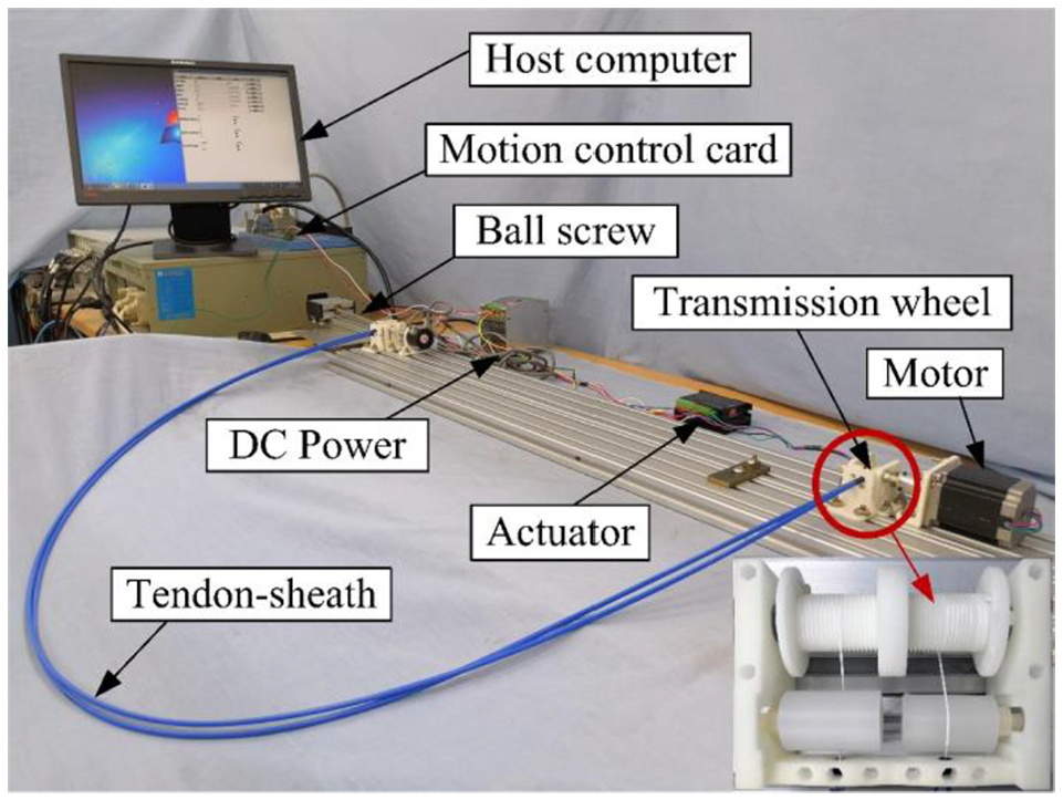
Experimental setup of tendon-sheath transmission system.
In the experiments, multiple datasets were tested for each experimental state. The average values of the multi-group data in the transmission were compared with the theoretical data values to calculate the error value of the system, as given by equation (38). In this study, the absolute value of the transmission deviation was recorded as the standard deviation.

where
The experimental and theoretical results were compared and the average results from the multi-group experiments obtained under the two different conditions were analyzed. The positive trajectories are shown in Figure 13. The maximum positive error was 2.88 mm when the loading was 0.5 kg with a 180° cumulative bending radius. The maximum positive error was 5.35 mm when the loading was 1 kg with a 540° cumulative bending radius. Furthermore, as shown in Figure 14, the maximum errors in the reverse hysteresis phase were 6.41 mm and 13.22 mm.
Comparison of positive trajectories from experiments and theory.

Comparison of negative trajectories from experiments and theory.
No significant differences were observed between the theoretical and experimental motion trajectories. The experimental trajectory was close to the theoretical trajectory, which thus verifies the correctness of the theoretical formulation.
Comparison of experimental data in three situations
Figure 15 shows the experimental data obtained from rotation of the driving wheels for one cycle when the tendon-sheath transmission system was loaded with 1 kg and 0.5 kg and when the cumulative bending radii were
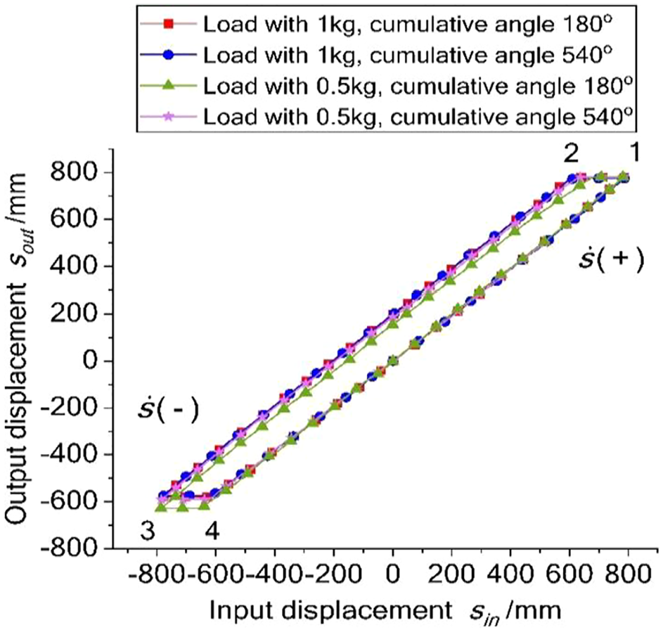
Displacement of the double tendon-sheath transmission system over one cycle.
Figure 16 shows the displacement error curves for the tendon-sheath system in the four cases after movement of 785 mm in the clockwise direction from the starting point. As shown in the graph, the displacement error with the larger cumulative bending radius was 10.37 mm under the 1 kg load, while the corresponding error with the smaller bending radius was 4.808 mm. The displacement error with the larger cumulative bending radius was 3.21 mm under the 0.5 kg load, while the corresponding error with the smaller bending radius was 1.77 mm. The experimental data indicate that the transmission error is generated from the transmission between the driving wheel and the follower wheel because of the characteristics of the tendon itself and the friction between the tendon and the sheath. Additionally, the displacement error will accumulate as the transmission distance increases. However, the displacement error increased gradually up to approximately 2/3 of the stroke, and the remaining 1/3 of the displacement error then decreased gradually. Because the majority of the tendon will be in the elastic elongation stage when the driving wheel rotates, the error will accumulate gradually. In the latter stages of the motion, the tensile force in the first half of the tendon will gradually increase with the winding of the driving wheel, thus resulting in greater tension than the initial tension at the driving end. Therefore, the rotational degree of the follower end will be greater than that of the driving end in the later stages of the motion. The cumulative error is thus lower during the early stages.

Displacement error of double tendon-sheath transmission system during positive movement.
Figure 17 shows the displacement error of the reverse movement that followed the positive movement of the double tendon-sheath system. The displacement error with the larger bending radius was 205.99 mm under the load of 1 kg during reverse operation, while that with the smaller bending radius was 202.33 mm. Under the 0.5 kg load, the displacement error with the larger bending radius was 187.06 mm, while that with the smaller bending radius was 156.28 mm. During the initial stages of the transmission, the tendon gradually changes from the relaxation stage to the tensioning stage. Therefore, the follower wheel does not immediately produce any movement in tandem with the rotation of the driving end. When the driving end overcomes the relaxation of the tendon and gradually becomes tensioned, the follower wheel then begins to move. Because of the coupling characteristics of the double tendon-sheath system, the error after the change in direction was much greater than that observed during positive driving.

Displacement error of the double tendon-sheath transmission system during negative movement.
Figure 17 also shows that a larger cumulative bending radius will produce more friction in both the transmission and the reverse hysteresis, regardless of the transmission load. These experimental data indicate that when the same cumulative bending radius is used, a greater positive error increment is observed in the system with the heavier load. The hysteresis increment in the system with the heavier load was smaller than that in the system with the smaller load after the change in the transmission direction. Because the cumulative bending radius increased, the friction force of the tendon also increased. However, the increase in the load meant that the larger cumulative radius produced more friction, which then led to a higher positive transmission error. The relaxation increment in the tendon under a larger load would be smaller than the increment under a lighter load. Therefore, when the cumulative bending radius increased, the increment in the hysteresis for the transmission system with the larger load was less than that for the transmission system with the smaller load. Similar conclusions to those of the previous theories could be determined based on the characteristics of the theoretical formula.
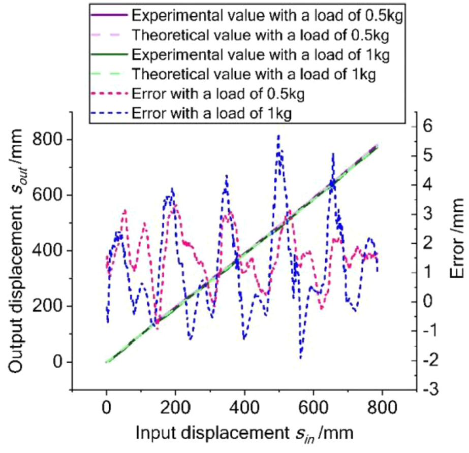
Figure 18 compares the experimental data acquired under different transmission system loads for the same cumulative bending angle. The positive movement of the driving wheel was 785 mm, and the displacement errors under loads of 0.5 kg and 1 kg were 3.85958 mm and 7.42479 mm, respectively. For the reverse operation, the displacement errors under loads of 0.5 kg and 1 kg were 187.09167 mm and 205.99708 mm, respectively. The figure shows that when the cumulative bending radius is the same, a heavier load results in greater positive and reverse errors. The larger load means that greater tension is required and this results in greater friction.
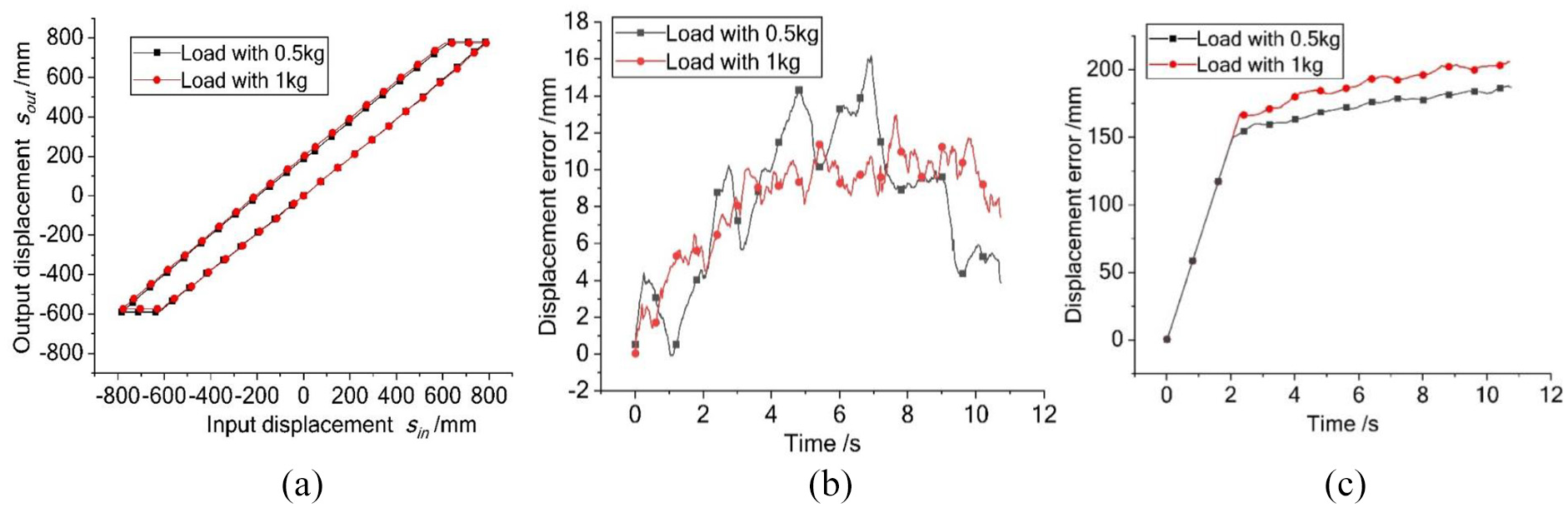
Comparison between different loads at the same cumulative bending radius.
Compensation experiments
The proposed tendon-sheath system is driven using a stepper motor. The elastic tension and the bending of the sheath, along with the friction between the tendon and the sheath and that between the tendon and the transmission wheel, will lead to some errors during movement. By establishing appropriate formulas for the transmission characteristics of the tendon-sheath system, the forward and reverse errors can then be calculated using the driving input force at the proximal end. However, the large-scale transfer characteristics of the system described in this paper cannot be compensated by simply measuring the proximal force. The particular nature of the application environment means that encoders that are suitable for nuclear magnetism applications must be used.
By measuring the displacement of the follower end during the initial stage of the movement, the initial pull power could be calculated in real time, and the corresponding tendon elongation and system hysteresis characteristics could then be estimated by calculating the initial tensile force. In this way, the system could be fed forward, thus compensating for both the positive displacement transmission and the hysteresis characteristics of the reverse motion. In addition, the compensation reflection time of the system could be reduced. Using the data collected by the encoder, error compensation could also be performed in real time. Therefore, the corresponding transmission error model can be expressed as follows:

where
The proposed system is designed such that the tendon is subjected to multi-layer winding in both the driving wheel and the follower wheel. The nonlinearity of the tendon material produces viscous friction, and the tendon and sheath motions during transmission also generate friction. Therefore, the LuGre friction model 28 was used to compensate for the nonlinear sliding deformation and friction hysteresis during the transmission process.
The mathematical expressions for the LuGre friction model are given as follows:
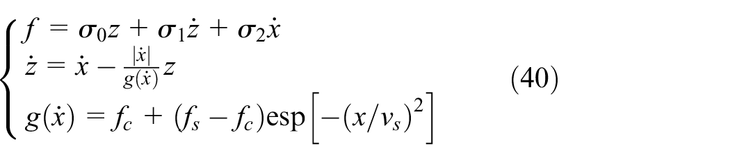
where the coefficients
The parameters of the LuGre model can be identified from the experimental data using the least-squares method and a genetic algorithm. In this study, we found that the static friction factor
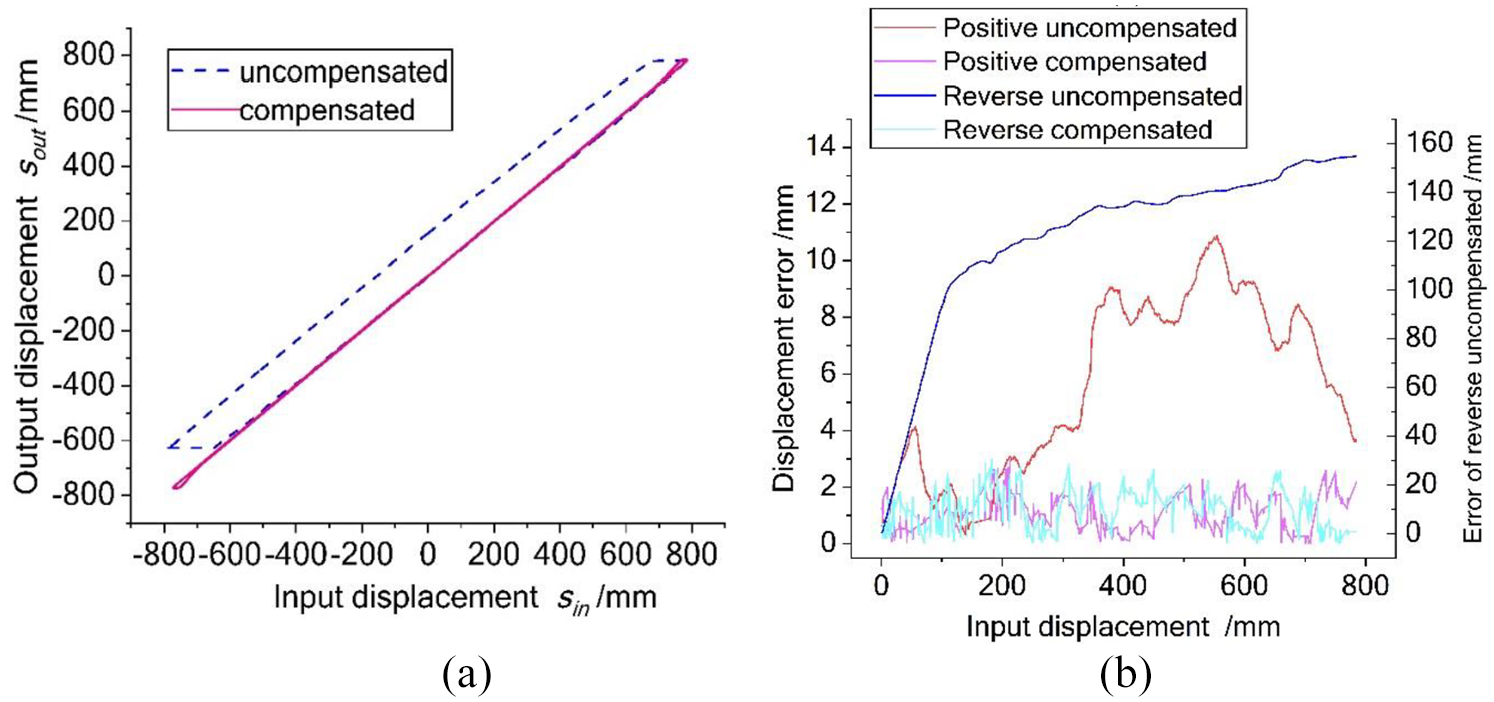
Comparison of experimental motion trajectories and errors before and after compensation under a load of 0.5 kg with a cumulative angle of

Comparison of experimental motion trajectories and errors before and after compensation under a load of 1 kg with a cumulative angle of
Figures 19(a) and 20(a) show the experimental motion trajectories. A significant error was still present in the commutative hysteresis phase when no compensation control was applied. However, the hysteresis error of the positive motion was reduced significantly after the compensation. Although the compensation can reduce the hysteresis error, the actual relationship between the input and the output remains nonlinear.
Figures 19(b) and 20(b) show the average and standard deviations of the errors of the double tendon-sheath system in the positive and hysteresis stages for the two experimental cases. Using the compensation mechanism, the positive operating error could be controlled in the range from 1.14–1.24 mm and the average hysteresis error could be controlled in the range from 1.32–1.59 mm. These results are sufficient to meet the requirements of long-distance and large-stroke transmission applications.
Conclusions
In this article, based on the critical driving technology requirements for robots operating in nuclear magnetic environments, a new type of double tendon-sheath transmission system has been proposed that offers long-distance and large-stroke power transmission. The proposed system uses a double broken-line groove structure that can effectively avoid the phenomenon of tendon entanglement when the tendon is wound. Therefore, the transmission accuracy can be improved further. The friction model of the tendon winding process and the transmission and hysteresis model of the tendon-sheath system have been established, and an experimental device was constructed. The experimental data were compared with the theoretical model to verify the correctness of the model.
Experiments were conducted under various conditions and the special transmission law of tendon-sheath transmission was derived. On this basis, the friction and hysteresis phenomena were compensated and precise position control was realized. A position compensation experiment demonstrated the validity of the proposed compensation mechanism and the improved control performance. The tendon-sheath transmission system proposed in this article is not limited to application to robots for use under nuclear magnetism conditions. The proposed system could be used for any robot that requires long-distance, large-stroke transmission, and the paper provides a theoretical basis for researchers who wish to achieve this functionality.
The goal for future work on this system is integration of this unique tendon-sheath system and breast intervention robots into medical experiments. In this study, the experimental platform was only applied to degree of freedom (DOF) control of the robot joints. Therefore, to meet the requirements of these robot applications, multiple-DOF (more than five) movements that combine advanced robotic technology with measurement technology will be studied. Furthermore, a rigid–flexible coupling analysis between the robot end and human tissues will be investigated to enable more complex tasks (e.g., removing target tissue while bypassing blood vessels) to be performed. In addition, tactile problems must also be considered to help surgeons to perceive organizational stress.
Footnotes
Handling Editor: James Baldwin
Declaration of conflicting interests
The author(s) declared no potential conflicts of interest with respect to the research, authorship, and/or publication of this article.
Funding
The author(s) disclosed receipt of the following financial support for the research, authorship, and/or publication of this article: The work was supported by the National Natural Science Foundation of China (51675142) and the Natural Science Foundation of Heilongjiang Province (ZD2018013).