
Abstract
Friction behavior is an important component of the metal-cutting mechanism. A simple and effective friction device that can yield the desired friction characteristics is required. In this article, a friction device with a solid–liquid–gas vibration reduction was proposed to research the interface friction characteristics. The interface friction characteristics of cupronickel B10 and YG6 were obtained through the new friction device, including the friction force, friction temperatures, and friction coefficient. The results show that an experimental solid–liquid–gas vibration reduction is feasible and effective to obtain the interface friction characteristics. The relationship between the friction-interface temperature T2 and the measured-point temperature T1 that was obtained by a heat-conduction model is linear. For cupronickel B10 and YG6, the friction coefficient gradually decreases with an increase in friction speed, and increases initially and then decreases with an increasing load. Based on the effect of friction temperature, friction speed, and load, a friction model for the interface friction characteristics of cupronickel B10 and YG6 was obtained.
Keywords
Introduction
Tool-chip friction is one of the two basic behaviors in metal cutting. Tool-chip friction affects machining quality, tool life, and cutting performance. The cutting performance can be improved by studying the tool-chip friction characteristics. It is difficult to analyze tool-chip friction directly by the cutting method because factors act on the tool-chip friction simultaneously. Therefore, it is necessary to establish a single-factor and single-level simulation experiment to study tool-chip friction.
Many studies have been conducted on tool-chip friction, and factors such as the tool material, friction speed, friction temperature, and friction load have been investigated. The effect of tool materials on tool-chip friction in AISI 1045 steel turning was studied by scientists.1,2 The research results indicate that in contrast with a WC-6Co tool, a PVD (Physical Vapor Deposition) coated tool can reduce the cutting force, the adhesive strength, and the tool-chip friction coefficient. In tool-chip experiments on the effect of speed, Xu et al. 3 found that several important tool-chip friction parameters of high-speed cutting (HSC) aluminum alloy 6061-T6 can be obtained through a high-speed orthogonal cutting method that can avoid the cutting-speed limitations. A dry-cutting friction model was proposed by Zhou, 4 and the friction behavior of AISI 1050 steel and 42CrMo4 steel at different friction speeds was experimentally simulated to verify the reliability of the model. The effects of friction speeds on the tool-chip friction coefficients were studied by some scientists.5–8 Temperature is one of the main factors to be considered. Hong et al. 9 observed that the friction coefficient at the tool–workpiece interface friction is reduced significantly when Ti6Al4V is processed at low temperatures. Natasha et al. 10 demonstrated that low-temperature processing reduces tool wear. The tool-chip friction coefficient against the friction temperature was analyzed in the literature.1,6 The load, as the main source of the cutting force, is an important factor that affects tool-chip friction. Therefore, some scientists used drying-sliding friction simulation experiments to research the variation of friction against load.6,11
Tool-chip friction is affected by the combined effects of an uneven load, the friction speed, the friction temperature, the friction area, the cutting depth, and other effects. 12 To resolve the individual effects of these factors, single-factor simulation experiments are necessary. Friction device is an important part of simulation experiment, which is used to simulate the friction behavior between tool and workpiece. So, a reliable and stable experimental device is crucial in the simulation experiments. The first, a friction device that simulates tool-chip friction was developed to study the interface friction performance of the tool and workpiece material.13–16 The second, a Type-Schwing-Reib-Verschleiss (SRV) friction device was used to analyze the friction performance of the tool and workpiece material in a linear contact.11,12,17 The third, a dry-cutting friction device was developed to simulate tool-chip friction.4,8,18,19 The last, the scratch test is also a method that can be used to study tool-chip friction. 20 Therefore, according to the number of papers on friction published by researchers in the field of metal cutting and the degree of influence of these papers, friction device has gradually become one of the research hotspots of many researchers in the field of metal cutting.
However, these simulated friction devices have obvious friction vibration during operation, which increase the difficulty and instability of obtaining the interface friction characteristics. Therefore, it is necessary to study and design a new friction device, which can effectively reduce the vibration in the simulation experiment. In addition, cupronickel exhibits anti-corrosion and other good performance. So it is used widely in aircraft carriers, warships, and other maritime areas.21,22 However, the cutting database indicates that limited friction characteristic data of cupronickel depress the development of the cutting performance of cupronickel. Therefore, this article presents a friction device that uses a solid–liquid–gas vibration-reduction method to obtain the interface friction characteristics of cupronickel.
Materials and methods
Experimental materials
The experimental workpiece material was cupronickel B10. Copper and nickel can be infinitely molten at a high temperature, and thus can form a continuous solid solution. The stable α-phase alloy is unrelated to the proportions of each element. Cupronickel has a high strength, a high corrosion resistance, a high hardness, and other excellent properties, and so it is used widely in the petrochemical, medical equipment, handicrafts, aircraft carrier, warships, and other important fields. The chemical composition as identified by energy dispersive spectrometry is shown in Figure 1. Nickel accounts for 13.32% and copper accounts for 86.68% of the experimental workpiece material.
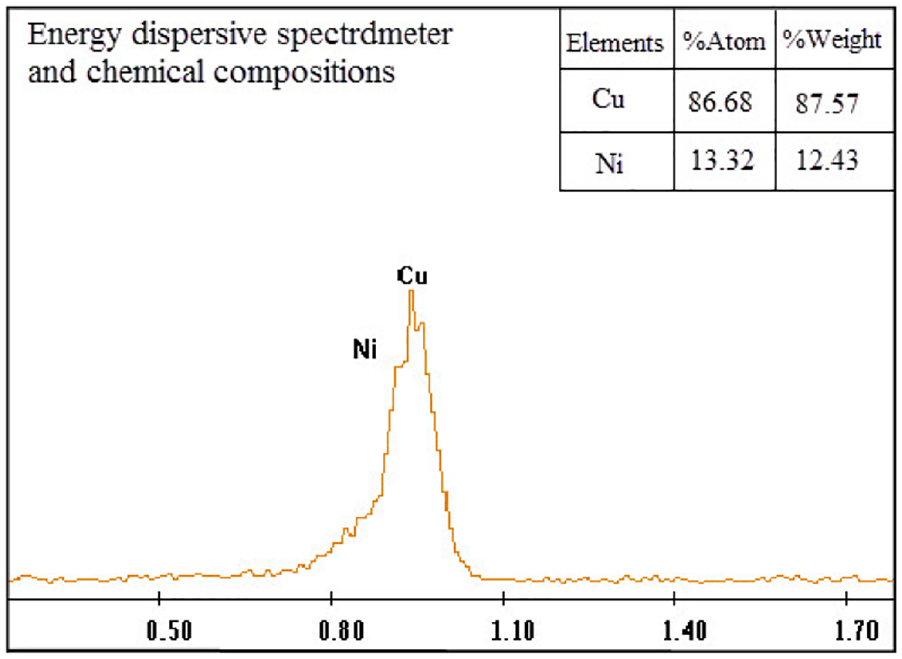
Chemical composition of cupronickel B10.
The experimental tool material was carbide YG6 (94WC-6Co). YG6 exhibits excellent performance of a high hardness, wear resistance, toughness, and heat resistance. In general, its hardness varies between 86 and 95 rockwell hardness C (HRC). YG6 exhibits a balanced physical performance, which makes it suitable as a good tool material.
Experimental friction device
A new friction device that is based on the solid–liquid–gas vibration reduction was proposed. The friction device as shown as Figure 2 includes a screw that is used to adjust the load, air bubbles, hydraulic oil, disc springs, a tool material rod, a workpiece, a dynamometer, and a thermocouple. The device uses a tool material rod and a circular tubular workpiece to simulate the tool-chip friction state of the cutting. As the device works, the tool material rod displays a feed movement and the workpiece exhibits a rotating movement. The tool material rod follows a spiral trajectory on the workpiece surface. The surface of the tool material rod exists in a friction state and the surface of the workpiece exists in an unprocessed state before it enters the friction state. The interface friction state produced by this friction device can simulate the cutting tool-chip friction state.

Experimental setup: (a) tool-chip friction experimental platform and (b) friction-device principle.
To reduce the vibration that is generated by friction and to ensure experimental stability and reliability, three kinds of vibration-reduction methods were used. The solid disc springs have a high elastic rigidity to provide good vibration reduction. 23 The liquid hydraulic oil enhances the vibration-reduction effect. Gaseous air bubbles in the hydraulic oil can reduce the friction vibration further. In addition, the oiling lock has a blocking action and the plunger rod has a free stroke in the plunger cylinder. They can also reduce the vibration.
The friction device can adjust the load to simulate the tool-chip friction load. The compression of the disc spring will change as the adjustable load screw is rotated. The amount of compression will result in a load on the rotating workpiece through the tool material rod. The load ranges from 0 to 80 N. A temperature measuring hole of 0.6 mm diameter was machined near the friction end of the tool material rod. A K-type thermocouple was installed in the hole. The thermocouple can measure point temperature T1. Based on the heat-conduction reverse-seeking method, the relationship between the friction-interface temperature T2 and the measured-point temperature T1 could be obtained.19,24 Then the friction-interface temperature T2 could be acquired. The friction force and load were measured by using a Kistler 9257B dynamometer.
Based on the proposed friction device, the experiment was carried out on a CTX 310 lathe. The acquisition frequency of the thermocouple acquisition temperature was 1 Hz and that of the dynamometer was 1000 Hz. The friction stroke on the workpiece was 100 mm. The load was 20 to 80 N. The friction speed was 200 to 450 m/min.
A heat-conduction reverse-seeking method
The friction temperature was difficult to obtain on existing temperature measuring devices, and the measured temperature was only the temperature of the measured point and not the temperature of the interface friction. It was necessary to obtain the relationship of the measured-point temperature T1 and the friction-interface temperature T2. So, a heat-conduction reverse-seeking method by considering heat conduction was proposed in this article. The heat-conduction model by using Workbench was shown in Figure 3. The temperature measuring hole of 0.6 mm diameter was machined near the friction end of the tool material rod. A K-type thermocouple was installed in the hole. The temperature range measured of the K-type thermocouple is 0 to 1300°C. The acquisition frequency of the thermocouple acquisition temperature was 1 Hz. The measured-point temperature T1 was obtained by the thermocouple. The thermal properties of cemented carbide YG6 were listed in Table 1.

Friction temperature obtained using the heat-conduction reverse-seeking method: (a) 100% area, (b) 50% area, (c) 25% area, and (d) 12.5% area.
Thermal properties of cemented carbide YG6.

Because the actual friction contact area varies, 100%, 50%, 25%, and 12.5% of the friction interface were loaded with temperature of 50°C to 500°C. The initial and reference temperature is 20°C. The rake face average temperature was loaded on the interface friction. The effect of convective heat transfer was considered by the heat-conduction reverse-seeking method. For example, air convection is considered, but cutting fluid convection is not considered. Since the mode of friction is dry friction, there is no liquid convection, and the air convection was loaded on other faces. The convective heat transfer coefficient of the air is 10 W/(m2°C). All the numerical simulations of this method work as a steady heat transfer.
Experimental results and discussion
Effect of solid–liquid–gas
The disc spring is formed from several matching units that consist of two face-to-face disc pieces. A large force will result as the disc spring deforms only slightly and so it is able to absorb the vibration energy. Therefore, it can be used as a vibration-reduction material. In the device, the load that is caused by the adjustable screw is transmitted through the two group disc springs and then acts on the contact surface between the tool material rod and the workpiece. During the friction process, the two group disc springs that are located in the oil reservoir will provide a dampening force, which will reduce and absorb the friction vibration. Hydraulic oil in the oil reservoir is highly viscous and incompressible. Because the friction device is excited by the friction vibration, the friction vibration will be reduced first by the front disc spring and transmit the vibration to the hydraulic oil. The hydraulic oil will generate friction with the inner oil-reservoir wall and the internal friction in the hydraulic oil molecules, which will result in dampening to absorb the vibration energy. In the same way, the moving parts in the friction device will generate friction heat because of friction, and the energy source of this part of friction heat is friction vibration energy, so as to effectively absorb the vibration energy to reduce the vibration. Air bubbles in the hydraulic oil are compressible. So they can reduce the vibration amplitude and absorb the vibration energy.
Through vibration reductions of the solid -liquid -gas three-phase interaction, the vibration of the friction experiment exists in a stable. Classic experimental results that are obtained by the proposed method and device are shown in Figure 4. A steady load and friction force can be obtained, which indicates that the proposed friction method and device are feasible and successful. As shown in Figure 4, the vibration frequency and amplitude of the load and friction force are significantly reduced, both of which prove that the solid–liquid–gas friction device has the effect of reducing vibration. The load decreases slightly with the change of test time during the experiment. This is because in the process of friction, friction temperature has a thermal softening effect on the workpiece. This slight variation is effectively reduced by taking the average value. The force results were shown in Figure 4 that exhibits no jamming signals as caused by the friction vibration, and show that the conceived solid–liquid–gas vibration reduction is effective and feasible.

Friction force and load: (a) 283 m/min, (b) 354 m/min, and (c) 424 m/min.
Friction temperature
Based on the heat-conduction reverse-seeking method, the relationship between the friction-interface temperature T2 and the measured-point temperature T1 could be obtained that was shown in Figure 5. The relationship between the friction-interface temperature T2 and the measured-point temperature T1 that was obtained by a heat-conduction model is linear. Then the friction-interface temperature can be obtained from the measured-point temperature and the relationship between the two temperatures.

Relationship between the friction temperature and the measured-point temperature.
It is considered that the actual interface frictional contact area varies during the experiment. The temperature 50 to 500°C was loaded on the friction interface of 100%, 50%, 25% and 12.5% respectively when the relationship between the measured-point temperature T1 and friction- interface temperature T2 was obtained through the heat-conduction reverse-seeking method. And the relationship is obtained under unsteady heat exchange.
The temperature T1 at the measured point obtained by the K-type thermocouple varies with the test time and tends to be stable gradually. Moreover, the interface friction temperature T2 obtained by the heat-conduction reverse-seeking method is linear with the temperature T1 at the measured point. Therefore, the interface friction temperature also changes with the test time and tends to be stable, and the interface friction temperature in the steady state is selected as the friction temperature of the current experimental environment.
One group of results is shown in Figure 6. The average value of the interface friction temperature of these four different interface contact areas is as the friction temperature. So, the error of experiment is reduced effectively. As shown in Figure 6, the starting point of friction temperature change is added, which better reflects the change of friction temperature during the experiment in unsteady heat transfer. It also shows that the temperature curve is smooth and reliable, which shows that the heat-conduction reverse-seeking method is effective. With an increase in friction time, the friction temperature will increase to a certain value and then trend to a steady state value of 90°C.
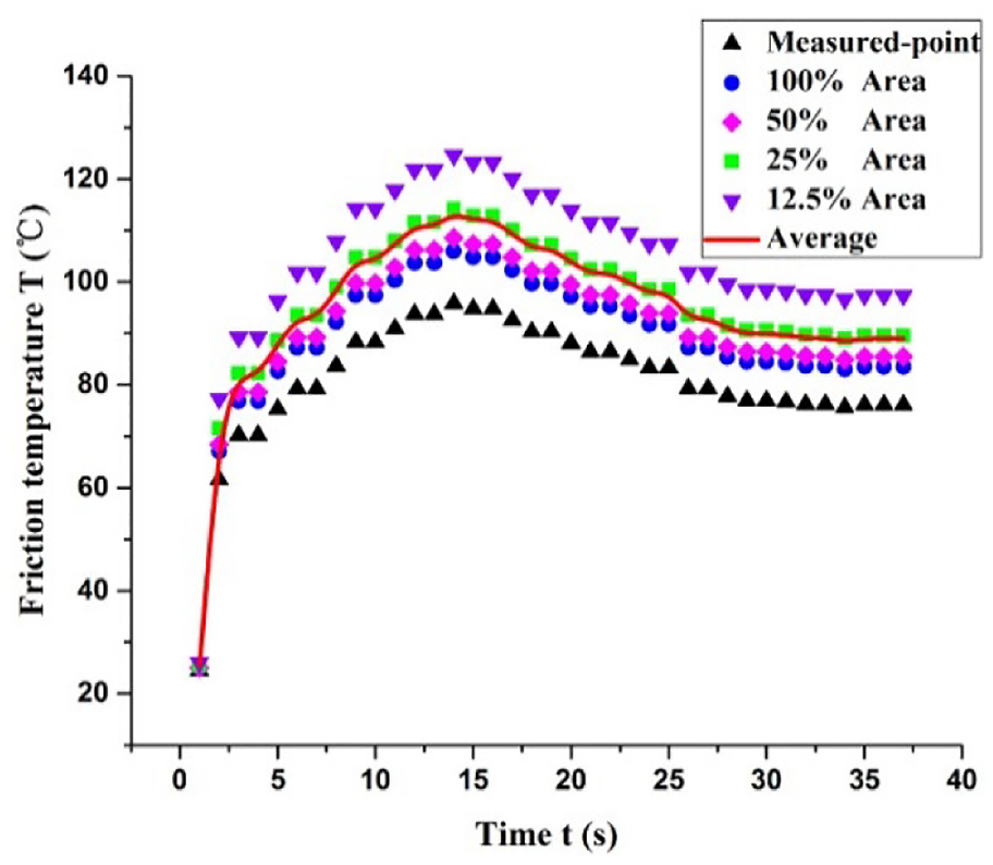
Friction temperature versus time at 212 m/min and 75 N.
Effect of friction speed
The change in tool-chip friction coefficient with friction speed is shown in Figure 7. The friction coefficient decreases gradually with an increasing friction speed, which provides evidence for the phenomenon that the cutting force decreases with an increasing cutting speed.

Friction coefficient against friction speed (including friction temperature).
The friction-interface temperature increases significantly as the friction speed increases, and more friction heat was produced with the increase friction speed, resulting in higher friction temperature. As shown in Figure 8, the friction temperature was increased by the increase in friction speed. The higher the friction temperature, the more pronounced the thermal softening effect. Higher friction temperature will soften the material, reduce cutting forces, and increase tool wear. The increasing friction temperature results in a softening of the material and a reduction in shear yield stress, which will reduce the friction coefficient. At a low speed, the effect of thermal softening is so small that a high friction coefficient results, and at the low speed, the friction temperature promotes the mechanical wear of the workpiece material, which improves the shear yield stress. When the friction temperature nears early melting temperature, the friction temperature causes the workpiece material at a peak point to reach an early melting phenomenon, which produces a lubricating layer. The thermal softening effect appears gradually at the same time, and the shear yield stress is reduced. Thus, the friction coefficient decreases. With an increase in friction speed, the thermal softening effect increases. When the increasing surface adhesion and the thickening lubrication layer reach a dynamic equilibrium, the shear stress of the material also reaches a new dynamic equilibrium. The friction coefficient tends to stabilize that was shown as a smooth friction coefficient curve results. At a friction speed of 200 to 450 m/min, the tool-chip friction coefficient of cupronickel ranged from 0.22 to 0.95.

The friction temperature versus friction speed.
Effect of load
The results for the adjusting load experiments are shown in Figure 9. With an increasing load, the friction coefficient shows an initial increasing and then decreasing trend. For loads of 20 to 80 N, the tool-chip friction coefficient ranges from 0.15 to 0.95.

Effect of load: (a) friction coefficient versus load including friction temperature and (b) the friction temperature versus load.
The phenomenon is analyzed as follows. From the perspective of tribology, the surface of the metal material consists of peak points. The friction interface occurs at the peak point so that the friction exhibits a mechanical occlusion state. During friction, cupronickel experiences a certain wear so that some friction plates form on the worn surface by worn particles. As the friction proceeds and the load increases, the friction plate is compacted gradually, and a tribofilm and even a new friction surface will form. The microstructure of the tribofilm as observed by scanning electron microscopy is shown in Figure 10. It can observe more residual tribofilms under higher load. A simplified tribofilm formation process is shown in Figure 11.

Microstructure feature of tribofilms.

Tool-chip friction stages of cupronickel: (a) low loads and (b) high loads.
Friction behavior is an important phenomenon in metal cutting, which is influenced by many factors such as load, friction, speed, and friction temperature. Therefore, friction coefficient is affected by various friction factors, and this multi-factor influence process is a dynamic influence process. On one hand, the tribofilm isolates the interaction between the tool material rod and the workpiece, and acts as a lubricant, which results in a decreasing friction force, and with the increase of the load, especially when the load increases to more than 50 N, a large number of tribofilms will accumulate in the friction interface to form a lubrication layer. The lubrication effect is more obvious in higher load. On the other hand, for loads below 50 N, worn particles constitute an incompact tribofilm, which increases the shear area of the workpiece material and the friction force. Of course, as the load increases, the shear area increases and the friction becomes more intense. Moreover, friction temperature is one of the important factors that affect friction behavior. High friction temperature will have an obvious thermal softening effect on the workpiece, reducing the yield strength of the workpiece and reducing the friction.
For the load below 50 N, with the increase of the load, the shear area and the friction increase. But the effect of thermal softening is not obvious. Therefore, the friction coefficient increases. For the load above 50 N, with the increase of the load, the lubrication effect of the lubrication layer formed by the tribofilm is improved, and the thermal softening effect is significantly increased. So the friction coefficient goes down. Especially at 75 N load, the friction temperature rises sharply. The high friction temperature causes the workpiece to soften sharply. So, the friction coefficient is low.
Tool-chip friction model of cupronickel B10 and YG6
The friction temperature, friction speed, and load are the three major influencing factors of friction coefficient. The friction behavior was affected by the friction coefficient. Taking account of influencing factors is important on the tool-chip friction. So, an empirical friction law was proposed as 19

In equation (1),

In equation (2), T is the friction temperature,
The friction speed effect coefficient
The friction temperature, the room temperature, and the cupronickel B10 melting temperature were 55°C to 75°C, 20°C, and 1100°C. According to equations (1) and (2), the relationship of the friction speed effect coefficient


Friction speed effect coefficient
The friction temperature, friction speed, and load were considered when the load effect coefficient


Load effect coefficient
An empirical tool-chip friction law of cupronickel was proposed based on the friction temperature, friction speed, and load. According to equations (1) to (4), the empirical friction law of cupronickel was proposed as

Conclusion
This article aims to resolve the problem of friction vibration and to determine the single-factor effect on tool-chip friction from multiple factors. An experimental method of solid–liquid–gas reducing vibration was proposed and used to acquire the interface friction characteristics of cupronickel B10 and YG6. The results are as follows:
The experimental method of solid–liquid–gas vibration reduction is feasible to obtain tool-chip friction characteristics. The friction device can reduce the friction vibration and achieve a friction load adjustment. The method can also be applied to obtain the tool-chip friction characteristics of other metals.
The relationship between the friction-interface temperature T2 and the measured-point temperature T1 that was obtained by a heat-conduction model is linear.
The tool-chip friction coefficient of cupronickel B10 decreases gradually with an increasing friction speed. The friction coefficient increases initially and then decreases with an increasing load.
Based on the effect of friction temperature, friction speed, and load, an empirical friction coefficient law for the tool-chip friction of cupronickel B10 and YG6 was obtained.
Footnotes
Appendix 1
Handling Editor: Crinela Pislaru
Declaration of conflicting interests
The author(s) declared no potential conflicts of interest with respect to the research, authorship, and/or publication of this article.
Funding
The author(s) disclosed receipt of the following financial support for the research, authorship, and/or publication of this article: This work was supported by the National Natural Science Foundation of China (51875045).