
Abstract
Breast cancer is one of the most frequent cancers and a major cause of cancer death in women. In this article, the design and control of a novel magnetic resonance imaging-compatible breast intervention robot are proposed. The dimensions and tolerance of the robot system are considered, and a novel pitching mechanism is designed to achieve a dexterous operation in the limited space. The magnetic resonance imaging compatibility of the robot materials is tested. The nonmagnetic structure and compact Cartesian mechanism of the robot allow it to operate safely in a magnetic resonance imaging scanner. According to the robot’s structure, a kinematics analysis based on a coupled motions model is established. The workspace simulation analysis of the robot proves that it is suitable for the whole breast surgery. To control the needle insertion tasks, the overall control system in the form of “personal computer (PC) + single-chip micyoco (SCM)” is designed. Finally, the motion control experiment is carried out, and the robot positioning error is 0.37 mm, which proves that the breast intervention robot and its control system designed in this article can meet the requirements of breast intervention.
Introduction
The incidence of breast cancer is increasing and the age of patients has tended to be younger in recent years. 1 Breast cancer is the major cause of cancer death for females from the age of 15 to 54 years. 2 If breast cancer is detected at the beginning stage, patients can often be cured. 3,4 As an early detection method, a breast biopsy extracts and analyses sample tissues by inserting a needle into the suspicious areas under the guidance of images, which is used to confirm whether the tissue is cancerous or not. The magnetic resonance imaging (MRI) technique can present a better performance in soft tissues than an ultrasound, computed tomography, and mammography. 5 In recent years, MRI has become much more popular in clinical diagnosis. MRI has already been used as an optimal strategy for guiding breast biopsy. The robot-assisted MRI-guided breast biopsy has received the most interest. However, because many available tools used today are not MRI-compatible, numerous challenges exist when using various medical tools and devices in an MRI environment. The term MRI-compatible or MRI compatibility is used to describe robots developed for the MRI environment. Lack of MRI compatibility results in many serious problems, such as image distortion, image noise, and generated heating that will seriously affect the quality of surgery. 6 The spatial constraints of high-resolution closed-bore MRI systems are expected to be overcome by the development of robotic manipulators for surgical instrumentation. 7
Over the past few years, the development of an MRI-guided breast intervention robot system has been addressed by some institutions and researchers. 8 –12 These research institutions have focused on different technology aspects and multiple robot structures. Park et al. developed an MRI-compatible robotic intervention system that incorporates a bendable needle intervention robot for breast cancer patients to overcome the space limitations of the MRI scanner. 13 Yang et al. developed a master–slave surgical system for a breast biopsy and both the slave and master robot had a control PC with data acquisition cards to control their configurations. 14 Navarro-Alarcon et al. presented the development of a new three-degree-of-freedom (3-DOF) robotic system has a Cartesian mechanism for an MRI-guided breast biopsy and conducted several motion control and magnetic compatibility experiments. 15
In addition, to work in an MRI environment, MRI-compatible robots are usually driven by four methods: remote actuation 16 (conventional electromagnetic actuators are placed outside the MRI scanner), piezoelectric motors, 17 hydraulic actuation, 18 and pneumatic actuation. 19 Piezoelectric motors have incomparable location accuracy and power density. 20 Chan et al. developed a piezo-driven robot that can operate in a closed MRI scanner. 21 However, the piezoelectric motors using commercially available motor drivers cause unacceptable MR imaging noise (up to 40%–80% signal loss) during synchronous movement of the robot. 22 Pneumatic actuation inherently could be designed intrinsically MR Safe. 23 Yang et al. used pneumatic cylinders to develop a 6-DOF robotic platform including a 1-DOF needle driver to perform a localization procedure for biopsy in MRI. 14 However, a major problem of pneumatic actuation is to maintain stability, which may lead to overshoot due to the nonlinear friction force and the slow response caused by long pneumatic transmission line. The hydraulic actuation provides high power output and could be potentially MR Safe. Kokes et al. designed an MRI compatible hydraulic needle driver for radiofrequency ablation of breast tumors, 24 but it is not ideal due to the fluid leakage and cavitation. 25 Therefore, remote actuation is an effective way for an MRI-compatible robot.
According to a comprehensive analysis of present situations, it can be ascertained that there are three main technical problems in the development of MRI-compatible breast intervention robots.
a. Limited space
The inner diameter of an MRI scanner is about 600 mm. 26 The operation space of the robot is very narrow after the patient is placed in the scanner, so it is necessary to design the robot structure appropriately so that it can meet the limited space requirements.
b. Material compatibility
When an MRI-compatible robot works, traditional control motors easily lose control by electromagnetic interference in the high magnetic field of an MRI scanner. Magnetic materials will affect the imaging effect of MRI. Metal medical devices cannot be used in an MRI environment.
c. Minimally invasive surgery (MIS)
MIS limits the size and number of cuts so is associated with less pain, a shorter recovery time, and fewer complications. Robots used for MIS must have a high positioning accuracy. The development of increasingly accurate robots has been one of the key issues in terms of the technique and capability of MIS. 27 Errors in sampling will lead to failure in the operation. Repeated operations will increase the trauma inflicted to the tissues.
For these problems, it is of great significance and practical value to design a breast intervention robot that can achieve a dexterous operation in a limited space with a compact structure, material compatibility, and high precision. Therefore, we introduce a novel MRI-compatible breast intervention robot and its control system that is intended to form the basis for a breast biopsy robot.
Design of the breast intervention robot
The details of the proposed seven DOFs compact Cartesian coordinate breast intervention robot have been conceptually depicted in Figure 1. According to the requirements in the space limitation, material compatibility, and MIS, Figure 1 depicts the configuration of the patient, support in the prone position, the breast intervention robot, and the MRI scanner. During the operation, the robot is placed inside the support in the prone position and the patient lies prone on the support. This is because, if the patient lies in the supine position, the target will fluctuate under the influence of breathing, which will affect the positioning accuracy. Lying prone makes breasts droop so that the influence of breathing is greatly reduced.

A seven DOFs compact Cartesian coordinate breast intervention robot model.
Dimension design
We consider the dimensions of the MRI scanner, support in the prone position, and the patients, as well as the tolerance among them. The inner diameter of an MRI scanner is about 600 mm and the height of the bed is 120 mm. The maximum chest thickness of an adult is 260 mm, the maximum shoulder breadth is 458 mm, and the maximum cervical spine point height in a sitting position is 675 mm, according to the human dimensions of adults. 28 It is shown by calculation and analysis that the setup requires support in the prone position to have a vertical height in the Z direction smaller than 220 mm and a width in the Y direction smaller than 480 mm. It does not have a strict limit on the length in the X direction. However, the available space in the Z direction is very limited. In our design, the length of the support in the prone position is set as 750 mm, the width is set as 460 mm, and the height is set as 205 mm. The breast intervention robot is placed inside the support in the prone position to perform the operation. The sizes of the robot are 380 mm in length, 340 mm in width, and 190 mm in height. The overall dimension of the device in an MRI scanner is shown in Figure 2(a). The working envelope to be reached by the robot should cover the volume of the breast, that is, the rectangular space with a size of 150 × 330 × 100 mm3, as shown in Figure 2(b). The dimensions comparison of the system in an actual case is presented in Table 1.

Dimension design: (a) the overall dimension of the device in an MRI scanner. The maximum chest thickness of an adult δ max = 260 mm. The maximum dimension of two grid fixed plates ξ max = 150 mm and (b) workspace of the breast intervention robot.
Dimension comparisons of the system in an actual case.

MRI: magnetic resonance imaging.
T MH means the minimum tolerance between the MRI scanner and human, T HS means the minimum tolerance between a human and support in the prone position, and T SR means the minimum tolerance between the support in the prone position and robot when the patient lies prone.
Structure design
The seven DOFs breast intervention robot includes a positioning module, puncturing module, biopsy module, and storage module. The positioning module based on the improved Cartesian coordinate form has four DOFs (X, Y, Z, and C). Three of them (X, Y, and Z) are intended to realize the linear motion in the X, Y, and Z directions. In the X direction, the opening and closing motion of the grid fixed plate is combined with the X direction positioning motion, which can reduce the DOF of the robot, thus reducing its complexity. The available space in the Z direction of the robot is very limited as motioned above, but the scope of work should be adequate. A pitching mechanism is designed to achieve a dexterous operation in a narrow space. The Z-slider is moved along the Z-axis to achieve the pitching motion, and the P-slider is moved along the P-axis for puncturing. The design of the pitching mechanism realizes the movements of both posture and position. We have not found similar designs in medical robots from an extensive literature search. The design of the pitching mechanism is shown in Figure 3.

The design of the pitching mechanism.
Cartesian coordinate robots have combined high reliability with ease of operation. The main characteristics embodied in the design of the pitching mechanism that based on the improved Cartesian coordinate form are structural stability, high precision, compact structure, and short posture adjusting time. Compared to the traditional Cartesian coordinate robot, the design of the pitching mechanism only needs slight posture adjustment to achieve full coverage of the target. For the same workspace, rectangle ABCD in Figure 4, traditional Cartesian coordinate robots have to move the length of CD along the Z direction, however, the pitching mechanism only need to move the length of C′D′, so its posture adjustment can be done in a shorter time. At the same time, the workspace extended to A′B′C′D′.

Comparison of two workspaces.
The other DOF (C) has been used to move and avoid obstacles (grid fixed plate) in the Y direction. The puncturing module is placed on the P-slider and designed to assist the biopsy module to complete biopsy surgery by driving the biopsy module (end-effector) to insert or withdraw the biopsy needle from the breast tissue, which needs one DOF (P). The breast intervention robot is expected to insert a needle at different pitching angles along the P-axis. The DOFs of the positioning module and puncturing module are shown in Figure 5.

The DOFs of the positioning module and puncturing module. DOF: degree of freedom.
The biopsy module includes a biopsy slider and biopsy needle. The biopsy needle is the end-effector of the system that consists of an inner needle, external needle, and sampling slot. The inner needle is a solid core needle with a diameter of 0.9 mm, and the external needle is an empty core needle with an inner diameter of 1 mm and an outer diameter of 1.2 mm. The angle of the needle tip is 30°. From the tip of the internal needle to the end of the base is 176 mm. Figure 6 shows a three-dimensional (3D) model of the biopsy module. According to the work principle of the semi-automatic cutting biopsy gun, the biopsy needle is designed to insert the inner needle through the lesion and then motivate the external needle. The shear force caused by the external needle is used to enter the lesion and leave the tissue sample in the sampling slot to complete the biopsy. One DOF (N) is needed to drive the biopsy slider to motivate the external needle. The storage module is designed to collect samples. Biopsy surgery usually involves several samples. It adopts a synchronous belt device for delivering samples, so one DOF is needed.

3D model of the biopsy module.
MRI-compatible material selection
The MRI compatibility of equipment mainly refers to the equipment being able to work inside the MRI scanner without interfering with the MRI scanner. The main requirement is not to use materials that actively or passively generate magnetic fields, such as a motor with electromagnetic coils, sensor, and magnetic materials like iron and nickel. In general, ferromagnetic materials, such as iron, steel, and copper, will cause the distortion of MRI images. Nonmagnetic stainless steel, platinum, ceramics, composite materials, engineering plastics (such as nylon, polyformaldehyde, composite resin, polypropylene, and polyurethane, which are among the most commonly available and versatile materials in additive manufacturing), and other paramagnetic materials can meet the compatibility requirements. To choose MRI-compatible materials for a breast intervention robot, an experiment of MRI compatibility has been carried out using some of the materials above. Experimental materials are shown in Figure 7.

Experimental materials.
The procedures of the MRI-compatibility experiment are as follows: Put the water phantom into the MRI scanner for imaging and obtain the undistorted image. Maintain the position of the water phantom, place the tested material near the water phantom for imaging, and observe the change of the water phantom image. If the tested material is MRI-compatible, the water phantom image should be consistent with the first step, or the water phantom image will be distorted. Each image is compared pixel-wise to the corresponding reference slice of water phantom with MATLAB. Boolean minus is carried out on the water phantom image obtained after placing the tested materials using MATLAB, and the degree of distortion is analyzed. Following the ASTM standard F2119.
29
The method of MR image analysis in detail can be found in the study by Neumann et al.
30
We measured some materials and parts such as aluminum alloy, cylinder, and steering gear (copper gear). However, the obvious interference could be clearly felt as soon as these materials near the MRI scanner, so there is no imaging scan for these materials. Copper, nonmagnetic stainless steel, and engineering plastics were put into an MRI scanner for imaging. MRI-compatibility analysis was carried out by analyzing the influence of those materials on the water phantom image, as shown in Figure 8.

The experiment of MRI compatibility: (a) copper, (b) nonmagnetic stainless steel, and (c) engineering plastic.
We did many measurements for each materials with the help of surgeons in the hospital and the results in Table 2 represent the universal phenomenon. The imaging results of MRI compatibility for an undistorted water phantom image and images after placing the tested material and after Boolean minus of tested materials are shown in Table 2.
The imaging results of the experiment of MRI compatibility.


MRI: magnetic resonance imaging.
When the copper was placed near the water phantom, water phantom image distortion occurred and there were large areas of blindness. Therefore, copper has a serious impact on MRI imaging quality, so it is not a suitable material for robots in an MRI environment. Nonmagnetic stainless steel had a little effect on the brightness of the water phantom image, but no image blind spot was generated, so it is an alternative material for MRI-compatible robots. The MRI image clarity was not affected by engineering plastics and no blind spot appeared. All tested materials of engineering plastics may be employed for devices placed in the field of view during MR imaging as no significant artifacts were measured. Engineering plastics are considered as the most ideal MRI-compatible material. We have checked with the surgeons that the image artifacts caused by the engineering plastics and nonmagnetic stainless steel to be negligible in MRI. To meet the requirements of MRI compatibility, after comprehensive consideration of material characteristics (density, elastic modulus, Poisson ratio, and yield strength), MRI compatible materials, such as nylon, polyformaldehyde, and nonmagnetic stainless steel, have been chosen to be the materials of the robot. Materials used for each part of the breast intervention robot are presented in Table 3.
Materials used for the breast intervention robot.
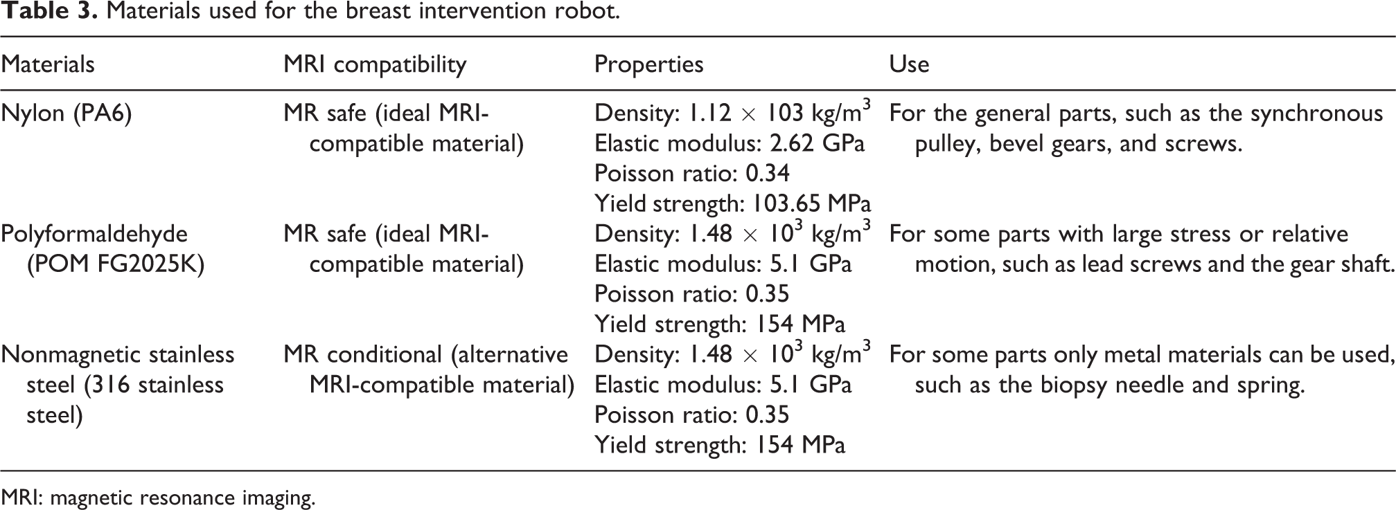
MRI: magnetic resonance imaging.
Experimental prototype robot
3D printing as additive manufacturing is a process of making 3D solid objects from a digital file. 3D printing allows for the fabrication of medical devices with complex geometries. The experimental prototype robot in our article is manufactured by 3D printing, which is shown in Figure 9. The manufactured procedure in detail can be found in the literature. 31

The experimental prototype of the breast intervention robot.
Actually, the purpose of the motion in the X direction is to fix breast tissues by moving the grid fixed plant and determine the origin (the position of the biopsy needle tip when tissues are fixed) of puncture movement before biopsy. The three DOFs of motion in the X direction, motion to avoid obstacles, and the storage module have no effect on the needle pose and positioning accuracy of the robot. The positioning accuracy of the presented robot is of interest to the community. Therefore, the experimental prototype robot has four DOFs, including motion along the Y-axis, pitching along the Z-axis, and motion along the P-axis and N-axis.
Kinematics analysis and workspace analysis
Kinematics model dimensions design
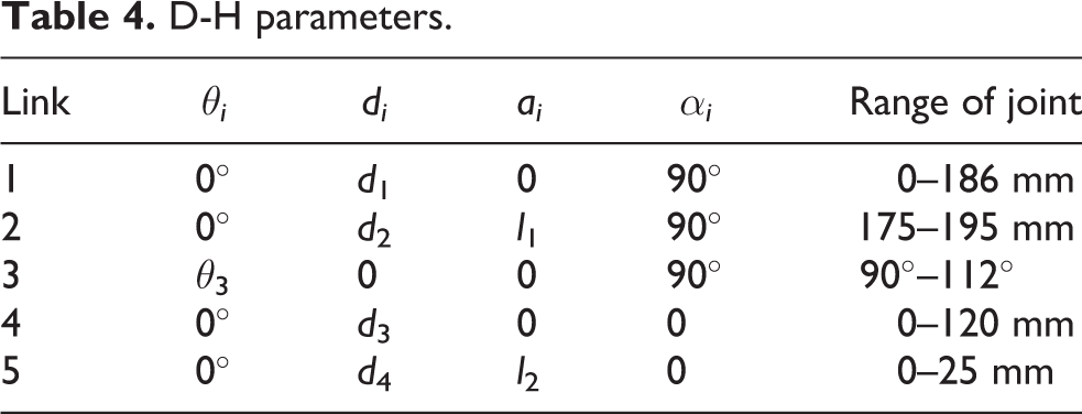
To obtain the position and orientation of the end-effector (biopsy needle) of the breast intervention robot during operation, it is necessary to establish kinematic equations that link the joint space with the coordinate space. D-H convention introduced by Jacques Denavit and Richard S. Hartenberg is the common practice for selecting reference frameworks in robotics applications. 32 The coordinate transformation of a robot consisting of N connecting rods constitutes the kinematics equations. The sizes of a robot and its kinematics equations define the space that the robot can reach, known as its workspace. Based on an analysis of the breast intervention robot structure, the coordinate system of the experimental prototype is established. The pitching joint is a joint with two DOFs, including one for parallel motion and one for rotation, similar to a cylindrical joint, 33 however, one motion is active and another motion is passive, that is to say, the two motions are coupled. In this case, D-H convention cannot work. Therefore, a virtual link is proposed while setting up the D-H coordinate system. A virtual link is fictitious and artificially added within the pitching joint and the motions on both sides of the virtual link are limited simultaneously, which has no effect on the other links. The kinematic chain configuration with a virtual link is shown in Figure 10. Actually, the pitching link of the breast intervention robot is designed to move along the Z-axis and the X-axis simultaneously. The length of the pitching link is certain. Therefore, once joint 2 moves, joint 3 has to move accordingly. According to the kinematic chain configuration, the D-H parameters and joint variables are presented in Table 4.
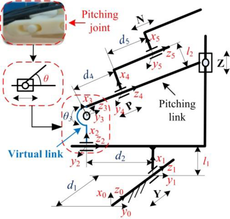
The kinematic chain configuration with a virtual link.
D-H parameters.
Coupled motions model
The virtual link is factitiously proposed to solve the kinematic analysis of a robot that has a cylindrical joint. As mentioned above, the motions of joint 2 and joint 3 are correlative movements; that is, there is a coupling relationship between joint 2 and joint 3. It is essential to capture this coupling relationship by setting up a coupled motions model.
According to the kinematic chain configuration in Figure 3, a coupled motions model between joint 2 and joint 3 is established, as shown in Figure 11.

Coupled motions model between joint 2 and joint 3.
To clearly describe the coupled motions model, the symbol expressions of the coupled motions model are presented in Table 5. Among them, D-H parameters d 2 and θ 3 are variable.
Symbol expressions of the coupled motions model.
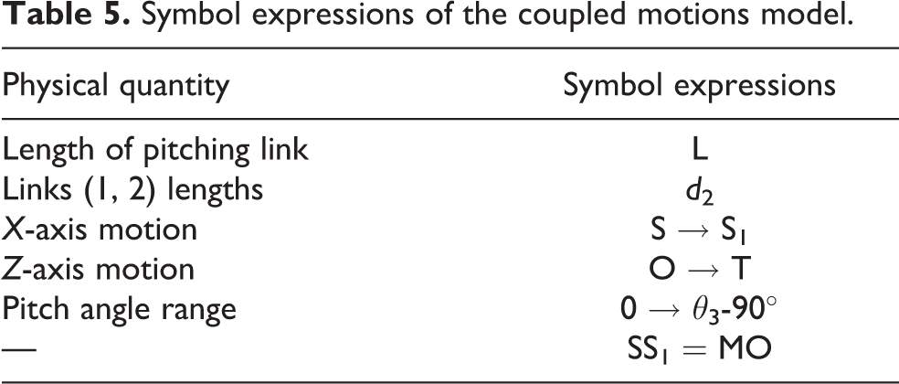
The initial state of the pitch link is in the position of SO, and the pitch angle is 0°. When the maximum of the pitch angle is reached, the pitch link is in S1T. If the Z-axis can move to the left along the X-axis, OT→MT′, the pitch link will move in a part of the circle around point S and has radius L. Then, a right triangle is formed, and the coupled equation between joint 2 and joint 3 can be obtained, as shown in equation (1)

Forward and inverse kinematics
To analyze the forward kinematics, kinematic equations of the breast intervention robot can be established and used to compute the position of the end-effector through giving specified values for the joint parameters. Forward kinematics specifies the joint parameters and computes the configuration of the kinematic chain. It is achieved by directly substituting the joint parameters into the forward kinematics formulas about the serial chain. The homogeneous transfer matrix of the breast intervention robot is obtained as

Here, cθi = cos θi , sθi = sin θi , cαi = cos αi , and sαi = sin αi , and according to equation (1), d 2 = L·sin θ 3.
Inverse kinematics makes use of the kinematics equations to determine the joint parameters that provide a desired position for the biopsy needle of the breast intervention robot. Inverse kinematics transforms the motion planning into trajectories of the joint actuator for the robot.
There are three types of inverse kinematic solutions: a complete analytical solution (closed-form solution), numerical iteration, and semi-analytical solutions. The principle of numerical iteration can be used to solve the inverse kinematic of the breast intervention robot. The final implicit functions are given in equation (3) as

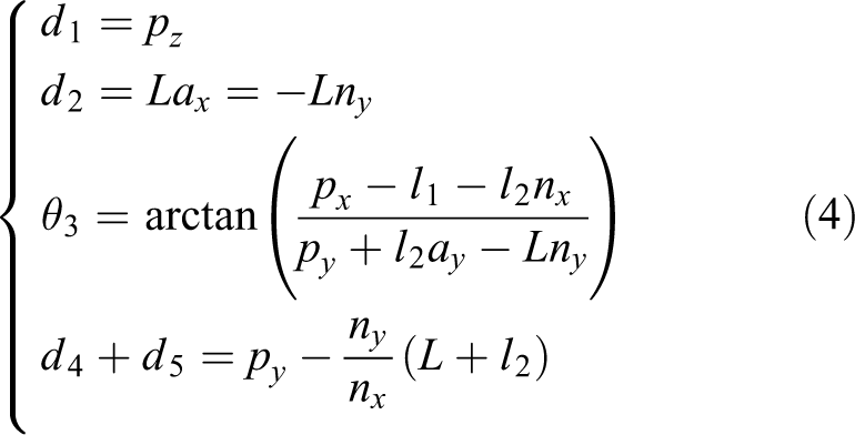
Based on equations (1) and (3), all these five variables are presented in equation (4) as
Kinematics analysis based on the coupled motions model raises new ideas to set up the kinematics model as the robot has a cylindrical joint and provides the necessary basis and references for the following research work of breast intervention robot control. In turn, motion control experiments of the breast intervention robot can prove the validity of the kinematics analysis based on the coupled motions model.
Workspace analysis
A workspace simulation model can be set up by the SimMechanics toolbox in MATLAB/Simulink and the movement simulation can be made according to the chain configuration and joint parameters of the breast intervention robot. A link model of the breast intervention robot is shown in Figure 12(a). The simulation results output the motion trajectory of the end point of the breast intervention robot, and the simulation results are output to the MATLAB workspace. The MATLAB drawing function is used to obtain the workspace simulation results in each plane.

The simulation of the workspace of the breast intervention robot: (a) link model, (b) projection of the workspace in the X–Y plane, and (c) projection of the workspace in the X–Z plane.
Projection of the workspace in the X–Y plane is shown in Figure 12(b), in which the dotted rectangle is the workspace of the robot in the X–Y plane presented in Figure 12(b), and its size range is 330 × 150 mm2. The simulation result of the workspace completely covers this area, so it satisfies the requirement of the workspace in the X–Y plane. Similarly, the projection of the workspace in the X–Y plane is shown in Figure 10(b), in which the dotted rectangle is the workspace of the robot in the X–Z plane presented in Figure 12(c), and its size range is 150 × 100 mm2. The simulation result of the workspace also completely covers this area, so it satisfies the requirement of the workspace in the X–Z plane. In conclusion, the breast intervention robot can meet the requirements of the workspace of the breast intervention.
The control system design and MR compatibility analysis of the breast intervention robot
The breast intervention robot system is divided into two parts: the robot structure and the control system. The control system refers to the operation and control of the robot according to the surgeon’s requirements to complete the specified motion. In this article, a low-cost and easy-to-operate control system for a breast intervention robot is designed to help replace manual operations.
Control system overview
For the control system, according to the special requirements of the control system of MRI-compatible breast intervention robots, the remote driving control method using stepping motors is designed. What’s more, a flexible shaft of nonmetallic material is selected to transfer power, and other control elements, such as stepping motors, are placed in the 1.5 m area outside of the MRI scanner and enclosed in a magnetic shield. The overall control system for the MRI-compatible breast intervention robot is shown in Figure 13. In our design, we adopt the master–slave control. Like the operation mode of Da Vinci robot, the accuracy is guaranteed by the surgeon according to the image feedback. A closed loop is formed through the mode of human–computer interaction.

The overall control system for MRI-compatible breast intervention robot.
Hardware design of the control system
Based on the control requirements of the breast intervention robot, not only the cost of technology development and its development cycle but the later maintenance and redevelopment should be considered. Combined with the development trend of the robot control system, the control system for the breast intervention robot is designed by the combination of a PC (as a high-level controller) + single-chip micyoco (SCM; as a low-level controller). The high-level controller is mainly able to complete the human–computer interaction, which is convenient for doctors to complete the operation more accurately; the low-level controller is mainly responsible for motor driver.
The control system for the breast intervention robot is composed of three parts: Arduino Mega 2560 SCM, a Ramps extender board, and an A4988 stepping motor driver. The Arduino Mega 2560 is a microcontroller board based on the ATmega2560 (data sheet). It has 54 digital input/output (I/O) pins (of which 14 can be used as pulse width modulation (PWM) outputs), 16 analog inputs, each of which provides 10 bits of resolution (i.e. 1024 different values), 4 universal asynchronous receiver/transmitter (UARTs) (hardware serial ports), a 16 MHz crystal oscillator, a universal serial bus (USB) connection, a power jack, an in circuit serial programmable (ICSP) header, and a reset button, and its control loop frequency is 50 Hz. Arduino Mega 2560 SCM and a Ramps extender board require an independent power supply. The hardware connection chart is shown in Figure 14. Arduino Mega 2560 SCM connects the PC to obtain a 5 V power supply through a USB port, and a Ramps extender board requires an additional 12 V power supply. A Ramps extender board is connected to an Arduino Mega 2560 board through I/O ports. Meanwhile, an A4988 stepping motor driver is connected to a Ramps extender board in the same way. The stepping motor driver has four pins: 2B, 2A, 1A, and 1B, which can connect the stepping motor (42BYGH47-401A).

Hardware connection chart.
Software design of the control system
The robot works according to the workflow diagram shown in Figure 15. When the robot starts to work, the axes are in the initial position, and the working image is obtained by the MRI scanner. When the target position is obtained from the image, the motion sequence of each axis is the X-axis, Y-axis, Z-axis, and P-axis when the robot starts to insert a needle. Finally, the biopsy slider moves along the N-axis to motivate the external needle and obtain suspicious tissues.

Robot workflow diagram.
Four stepping motors need to be controlled. To achieve noninterference and an independent operation among multiple users, a PC is used to control four stepping motors in a time-sharing and step-by-step manner. Combined with an interruption program, multiple sets of pulse waves are generated to control multiple motors. The whole control system of the robot transmits instructions through the high-level controller, and then receives instructions from the low-level controller and completes control of the stepping motor. The operating parameters of the stepping motors are sent from the high-level controller to the low-level controller through the serial ports. The control programs are designed using the Arduino 1.0.6 Software (IDE).
MRI-compatibility analysis
A lot of precaution is required when the breast intervention robot is working in the MRI environment because of the high magnetic field present in the MRI scanner. The standard F2503-13 of the American Society of Testing and Materials (ASTM) categorizes devices under the MRI environment to three different classes in terms of the safety 34 :
(1) MR safe: materials that do not cause known hazards due to exposure to any MR environment, (2) MR conditional: when the equipment is used in the specified MR environment with specific use conditions, it will not cause known danger to the patient or the medical team, and (3) MR unsafe: items that pose an unacceptable risk to the patient, medical staff, or other personnel in the MR environment.
MR safe or MR conditional material is a key element of robotic systems for the MRI compatibility. The MRI compatibility of all materials involved in the breast intervention robot has been presented in Table 3. All the materials of the robot are MR safe or MR conditional, thus we can make sure that the robot is MRI compatible.
If the robot in the MRI scanner with poor shielding, the image degradation and SNR drop will happen when the robot is powered. In our design, all motor drivers, control system, and other essential electronics are placed in the 1.5 m area outside of the MRI scanner to seal in the magnetic shield. The flexible shafts of nonmetallic material are selected to transfer power. The flexible shaft that can work in the MRI environment is proposed and manufactured by our research team (Chinese patent no: 201520687242.2). The breast intervention robot is cleaned and sterilized in the same way that any other minimally invasive components are cleaned and sterilized. The devices of the flexible shafts and control part are not sterilized but are covered with sterile sleeves.
Motion control experiment
In this article, motion control experiment is designed and carried out to test the feasibility of motion control of the breast intervention robot. Silicon phantom is verified to be a promising biomaterial suitable for breast tissue mimicking due to the similar mechanical properties and deformation property to human breast tissue. To prove that the robot and its control system designed in this article can meet the requirements of the breast biopsy, we performed insertions into a breast silicon phantom that was produced by Shanghai Honglian Medical Technology Group Co., Ltd (China). 35
To reduce the experiment cost and improve the efficiency, we select target points in breast silicon phantom and adopt the master–slave interaction mode to complete the breast intervention operation. MRI imaging procedure is simulated using the vision. The target is seen through the cameras. The surgeon is the operator to control the breast intervention robot to complete the breast intervention operation.
In this experiment, six lesions in breast silicon phantom were selected as target points. The robot was controlled by the control system to reach the target point. Then, the distance between the target point and the actual arrival point of the needle tip was calculated; that is, the positioning error of the robot. The procedures of the motion control experiment are as follows: Firstly, the experimental platform is set up according to the hardware connection method in the “The control system design and MR compatibility analysis of the breast intervention Robot” section, and the breast phantom is localized on the support in the prone position, and the breast intervention robot is placed under the support in the prone position. The experimental platform is shown in Figure 16. 2D to 3D coordinates conversion. The coordinates of the measured point (needle tip) in the image coordinate system are converted to the robot coordinate system (world coordinate system). A fixed point on the base of the robot was defined coordinate origin of robot coordinate system. To facilitate the measurements, a camera (the resolution is 1280e960) is put horizontally to the robot base and above the support in the prone position, and the 2D relationship between the image coordinate system and the robot coordinate system on the X–Y plane is obtained, as shown in Figure 17(b). Then, the camera is put vertically to the robot base and parallel with the side plane of the support in the prone position, and the 2D relationship between the image coordinate system and the robot coordinate system on the X–Z plane is obtained, as shown in Figure 17(c). Additionally, the spatial coordinate conversion relationship between the image coordinate system and the robot coordinate system is created, and the 2D to 3D coordinates conversion between the two systems is completed. The measuring method of the measured point coordinate is shown in Figure 17. Experimental platform for motion control of the breast intervention robot. The measuring method of the measured point coordinate: (a) four coordinate systems, (b) horizontal image on the X–Y plane, and (c) vertical image on the X–Z plane.


Four coordinate systems are involved: O-XYZ: robot coordinate system, unit: mm; O-XcYcZc: camera coordinate system, unit: mm; o-xyz: image coordinate system, unit: mm; uv: pixel coordinate system, unit: pixel; T: a target point in the robot coordinate system; t: imaging point of T in the image coordinate system and pixel coordinate system; fc: the focal length of the camera. Select a target point in the robot workspace (the area of breast phantom in Figure 16) as the target point A, and mark it as A (A
x
, A
y
, A
z
). Transfer the coordinate of target point A to the robot control system. Through a kinematics analysis of the breast intervention robot, the tip of the biopsy needle of the breast intervention robot is controlled to reach point A. After the robot reaches the target point, data measurement of the needle tip is carried out based on the measuring method of step (2) to measure the actual arriving position of the biopsy needle, the position coordinate of the needle tip is marked as B (B
x
, B
y
, B
z
). The Euclidean distance between the corresponding points A and B mentioned above is analyzed and compared. The distance is recorded as |AB|, which can be expressed as the robot positioning error There are five groups of repetitive steps (3)–(6) for each target. Six target points were randomly selected in the workspace of the breast intervention robot. Their coordinates in robot coordinate system are (75, 40, 80), (90, 60, 85), (100, 80, 90), (95, 110, 100), (120, 140, 146), and (90, 155, 160). The mean and standard deviation of the positioning error are obtained. Errors are recorded and analyzed.

In this experiment, the coordinate positions of target points are sent by the high-level controller, and the breast intervention robot is controlled to move until the biopsy needle reaches the target points. To different target points, the needle pose is also different. The needle pose depends on the location of focal point and the pose of pitching mechanism. The results of robot positioning errors are presented in Table 6.
The results of motion control experiments.

The average value of the robot positioning error is 0.37 mm, and the positioning error is in the range of 0.12–0.56. The positioning errors could be caused by the step loss and pulse change of stepping motors, a low transfer efficiency in the process of flexible shaft transmission, the processing precision of parts, and the mechanical assembling accuracy of the breast intervention robot. The clinical study 36 reports a lesion minimum size of 4 mm. The positioning error is less than one-tenth of the lesion size. Besides, the positioning accuracy of clinical surgery is about 1 mm according to the surgeons’ experience at this stage. It can be seen that the proposed robot and its control system can meet the accuracy requirements of breast interventional surgery positioning, so the end of the robot can accurately reach the location of the lesion. This further proves that the novel breast intervention robot and its control system designed in this article can meet the requirements of breast intervention.
Conclusions
In this article, we have presented the design of a novel seven DOFs compact Cartesian mechanism MRI-compatible breast intervention robot and manufactured an experimental prototype robot by 3D printing that can meet the requirements of the limited space, material compatibility, and MIS. The breast intervention robot was designed with nonmagnetic materials, and the remote driving control method using stepping motors was designed to allow it to operate safely in an MRI scanner. The dimensions of the MRI scanner, support in the prone position, and the patients, as well as the tolerance among them, were considered to determine the size of the breast intervention robot. A pitching mechanism was designed to realize the movements of both posture and position and achieve a dexterous operation in a narrow space. The main characteristics embodied in the design of the pitching mechanism that based on the improved Cartesian coordinate form are structural stability, high precision, compact structure, and efficient (because it needs the shorter posture adjusting time). The MRI compatibility of materials was tested to approve the MRI compatibility of the developed robot. The kinematics analysis based on the coupled motions model of the breast intervention robot was established, and the virtual link proposed factitiously can solve the kinematic analysis of robots with a cylindrical joint. The workspace simulation analysis of the robot by the SimMechanics toolbox in MATLAB/Simulink proves that it is suitable for the whole breast intervention.
To control the biopsy needle insertion tasks, a low-cost and easy-to-operate control system for the breast intervention robot was designed to help replace manual operations. The overall control system in the form of “PC + SCM” was proposed. Arduino Mega 2560 SCM was chosen as the control unit. The Ramps extender board and A4988 stepping motor driver were the other two parts of the hardware of the control system. The control programs were made by Arduino IDE. Motion control experiment was carried out, and the robot positioning error is 0.37 mm, less than one-tenth of the lesion size, which further proved that the breast intervention robot and its control system designed in this article can meet the requirements of the breast intervention.
Future work will include MRI validation for the breast intervention robot system, using force sensors to obtain puncture forces, and animal phantom study using the enhanced breast intervention robot system.
Footnotes
Declaration of conflicting interests
The author(s) declared no potential conflicts of interest with respect to the research, authorship, and/or publication of this article.
Funding
The author(s) disclosed receipt of the following financial support for the research, authorship, and/or publication of this article: This research was supported in part by the Natural Science Foundation of China (no. 51675142), by the Key Projects of Natural Science Foundation of Heilongjiang Province of China (no. ZD2018013), and by the Reserve Leader Funding Project of Leading Talent Echelon of Heilongjiang Province of China (no. 2501050628).