
Abstract
This article presents a centroid variability model–based controller of HITUWV (Underwater Welding Vehicle by Harbin Institute of Technology), an underwater welding vehicle, for automatic welding with high stability and accuracy. First, an accurate centroid variability model, which considers the coefficient changes of the HITUWV caused by the movements of a 3-degree-of-freedom manipulator, is presented to perform the dynamic characteristics of the HITUWV precisely. Second, a centroid variability model–based adaptive sliding model controller is developed for the HITUWV to complete centroid variability compensation. Experimental results indicate that the proposed centroid variability model–based adaptive sliding model controller demonstrates better performances in stability and accuracy than the conventional proportional–integral–derivative controller and the model-based proportional–integral–derivative controller. As a result, the centroid variability model–based adaptive sliding model controller holds great practicality and utility on the control of underwater operation with high stability and accuracy.
Keywords
Introduction
Recent developments in robotic technologies have heightened the applications of underwater vehicles (UVs) in nuclear power plants, such as daily inspection and urgent maintenance.1–5 Particularly, HITUWV (Underwater Welding Vehicle by Harbin Institute of Technology) is a UV which can complete automatic welding in spent fuel pools (SFPs).6–9 Due to the centroid variations caused by the movements of the welding system on board, it is of great significance to develop a compensation controller for the HITUWV to complete automatic underwater welding with high accuracy and stability.
By now, there are a great number of studies related to several control approaches of UVs. Among these approaches, the proportional–integral–derivative (PID) controller is the most widely used controller in industrial UVs.10,11 Kuo et al. 12 presented a PID controller for the depth station keeping of the underwater robot which is composed by a ground-based computer, a direct current (DC) power supply, an embedded system, and a propeller system. Ariyachartphadungkit et al. 13 designed an underwater robot consisting of eight thrusters and utilized a discrete PID controller to complete a 6-degree-of-freedom (DOF) motion based on the dynamic model of the designed robot.
Unfortunately, the performance of PID controllers in nonlinear systems is poor, and several optimized PID controllers are proposed to improve the adaption to nonlinearity, such as adaptive PID and fuzzy PID. 14 Moreover, in order to reduce the vibration caused by error-driven controllers, various advanced controllers have been proposed in the literature, such as sliding mode control, nonlinear control, adaptive control, fuzzy logic control,15–17 and neural network control. Tanakitkorn et al. 18 developed a sliding mode heading control system for overactuated, hover-capable autonomous underwater vehicles (AUVs) operating over a range of forward speed. The proposed control system is proven in the field trials to enhance vehicle response, yielding consistent and robust performance over the entire range of vehicle speeds, even when subjected to external disturbance. However, the chattering phenomenon in a sliding mode control system will greatly increase difficulties on the stable control of UVs. 19 Nag et al. 20 demonstrated an adaptive fuzzy logic–based controller for the depth control of an AUV. The controller receives deterministic information, the depth of the vehicle as input, and achieves imprecise reasoning and defuzzification to generate a deterministic control output which manipulates the pitch angle and hence the depth of the vehicle. But the fuzzy processing of information may reduce the accuracy and dynamic performance of controllers. 21 Cui et al. 22 proposed an integral sliding mode controller (ISMC) for underwater robots based on a multiple-input and multiple-output extended state observer (MIMO-ESO) with considering unmeasured velocities, unknown disturbances, and uncertain hydrodynamics in control design.
In general, all the abovementioned controllers are designed for either observation UVs or high-metacenter UVs without considering the centroid variability. However, HITUWV is a lower metacenter design UV, targeting completing underwater welding on walls of the SFP by hovering close to cracks with an arbitrary attitude. Consequently, the controllers mentioned above are not likely to meet our application requirements of underwater welding with high stability and accuracy.
In this work, a centroid variability model–based adaptive sliding mode controller (CVM-ASMC) is proposed which can be utilized by the HITUWV for underwater welding with high accuracy and stability. An accurate centroid variability model (CVM) is presented for describing the dynamic characteristics of the HITUWV precisely, and thus an accurate feedforward control with knowledge about the system can be utilized for the controller. Furthermore, in order to perform accurate centroid variability compensation, a CVM-ASMC is designed for the HITUWV. First, considering the coefficient changes of the conventional model caused by the movements of the welding system, the coefficients in the conventional model of the HITUWV are regarded as the functions of the positions of the 3-DOF manipulator, thus enabling the accurate description of centroid variability. Second, the proposed controller can predict the changes in center of mass, center of buoyance, and inertia tensor to complete centroid variability compensation; as a result, the stability and accuracy of underwater welding are achieved.
Experiments are carried out to validate the effectiveness of the proposed controller for centroid variability compensation. Experimental results show that the proposed CVM-ASMC performs better than both conventional PID controller and model-based PID controller. Consequently, the stability and accuracy of the HITUWV are achieved by CVM-ASMC during the process of welding.
HITUWV
As shown in Figure 1, the HITUWV is a tethered, open-frame underwater welding vehicle developed by Harbin Institute of Technology for inspection and welding in the SFP. The HITUWV is 1.06 m long, 0.68 m wide, and 0.61 m high with a mass of 150 kg.

(a) The overall structure of the HITUWV consisting of an open-frame UV body, a 3-DOF manipulator, and a welding system; (b) the whole system consists of HITUWV, an umbilical cable, a ground control box, and a welding power supplier; (c) the 3-DOF manipulator is constructed with three sets of a linear guide and a DC motor; (d) the welding system includes an underwater camera, a wire feeder, and a welding torch; (e) the thruster used by the HITUWV consists of a propeller, a water-lubricated bearing, a gear reducer, and a BLDC; (f) the self-developed micro-servo driver of the thruster, integrated with a 300-W power supplier, a BLDC driver, and an ARM-based controller.
The mobile system
The HITUWV is composed of a UV body and a 3-DOF manipulator as shown in Figure 1(a) and (c). The UV body has eight thrusters with vector distribution, and thus the overactuated configuration of the UWV can perform arbitrary attitude movements in the SFP. The structure of the 3-DOF manipulator, as shown in Figure 1(c), is constructed with three sets of a linear guide and a DC motor to perform trajectory tracking of arbitrary crack shapes.
The welding system, which includes a welding camera, a wire feeder, and a welding torch, is installed on the Z-axis linear guide as displayed in Figure 1(d). The stability of wire feed speed is in direct relation to the quality of the weld metal. Thus, the wire feeder needs to provide stable feed speed and enough friction torque. The pull-type wire feeder consisting of a DC motor and a pair of wheels was designed as shown in Figure 1(d). Due to the mini dimensions of the pull-type wire feeder, it can be installed close to the welding torch, and thus the stability of wire feed speed can be guaranteed.
To achieve the disparate goals of stable welding and flexible movement, the underwater thrusters composed of a propeller, a water-lubricated bearing, a gear reducer, and a brushless direct current motor (BLDC) have been developed and are presented in Figure 1(e). Due to the limited space of the power pressure housing, we developed a micro-servo driver of the thruster which is composed of a 300-W power supplier, a BLDC driver, and an ARM-based controller as displayed in Figure 1(f). Because of the unique motivation source of the UWV, the eight-bladed-propeller-type thrusters are equipped with vector distribution for arbitrary attitude movements. The initial configuration utilizes four thrusters for surge, sway, and yaw thrust and four for roll, pitch, and heave thrust.
The control system
As displayed in Figure 2, the HITUWV control system uses a two-part system design: the underwater control unit and the ground control unit. The two control units are connected by an umbilical cable which carries power lines and optical fibers. In the underwater control unit, a high-performance ARM-based microcontroller (MCU) is used to preprocess all the sensors’ data. And in the ground control unit, an industrial computer is utilized to perform complex calculations and process human input orders. The underwater control unit can communicate with the ground unit and upload all the sensors’ data but also process the data and perform autonomous motion and welding due to the existence of the high-performance MCU. Thus, even if the communications are disturbed, the HITUWV can still complete crack welding autonomously in case of emergency.
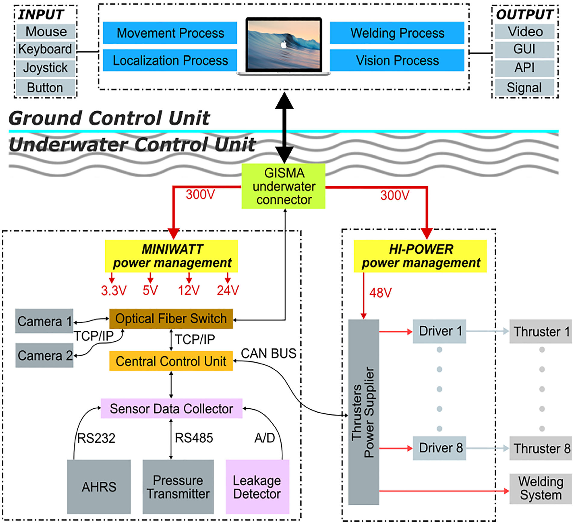
The architecture of the HITUWV control system. A two-part system design consists of an underwater control unit and a ground control unit. The two control units are connected by an umbilical cable.
CVM of HITUWV
Due to the lower metacenter design of the HITUWV, the centroid of the HITUWV is significantly changed while the 3-DOF manipulator is moving for welding trajectory tracking, as shown in Figure 3. The centroid variability has significant influence on the stability and accuracy of underwater welding.

The schematic of HITUWV’s centroid variability. The centroid of HITUWV is significantly changed while the 3-DOF manipulator is moving.
In order to describe the dynamic characteristics of the HITUWV, the CVM is proposed which considers the influence of the 3-DOF manipulator. It is convenient to define two reference frames as indicated in Figure 4(a) when analyzing the motion of the HITUWV under 6 DOFs. The body-fixed reference frame

Reference frames: (a) reference frames on the HITUWV and (b) the structure of the 3-DOF manipulator.
The CVM can be derived from the general Newton–Euler motion equation of a rigid body in a fluid medium. The CVM is highly nonlinear and coupled due to hydrodynamic added mass, lift, and drag forces, which are acting on the vehicle. The CVM can be expressed as follows

where

where
The structure of the 3-DOF manipulator, as shown in Figure 4(b), is constructed with three sets of linear guide and DC motor to realize crack tracking of arbitrary shapes. The Y-axis is fixed to the HITUWV body along
Assume that the centroid of the Y-axis guide in
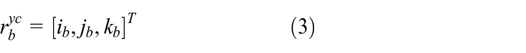
Thus, the centroid of the X-axis guide in

Similarly, the centroid of the Z-axis guide in

Consequently, the centroid of the three linear guides in

where * is x, y, or z which presents the X-axis, Y-axis, or Z-axis and
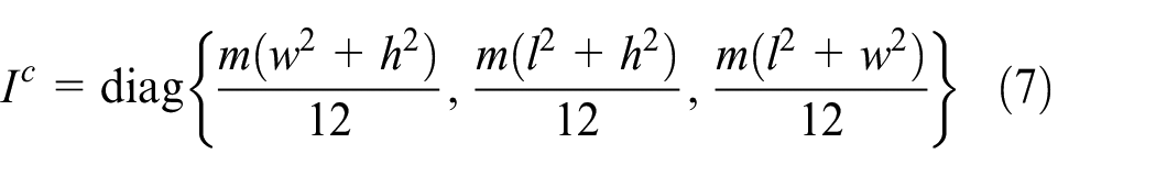
According to the parallel axis theorem, the inertia tensor

Therefore, the inertia tensors of the three linear guides are

Then the inertia tensors of the HITUWV are

where
The centroid of the HITUWV can be expressed as
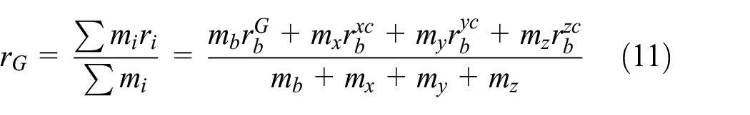
where

where
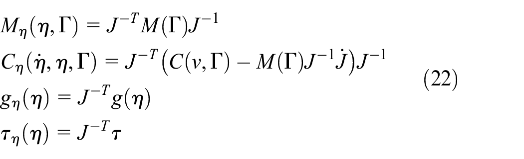
Consequently, the inertia matrix in equation (1) can be calculated by substituting equations (10) and (11) into it as follows

where the operator

The matrix of Coriolis and centripetal terms can be expressed as

The vector of gravitational forces and torques can be calculated by substituting equations (11) and (12) into it

Therefore, the CVM of the HITUWV can be written as

The relationship between the velocities in

where

According to equations (18) and (19), it can be expressed as

Consequently, the CVM in

where
CVM-ASMC
According to the CVM in

Considering the property of M, for an arbitrary value of s,

where

For

Substituting equation (26) into equation (24), the following can be obtained

The sliding surface of the controller is defined as

where

Consequently, the sliding surface can be re-expressed as

Then

Substituting equation (21) into equation (31), the following can be obtained

Let

According to equation (2), the control law can be designed as

where

where
In order to guarantee that
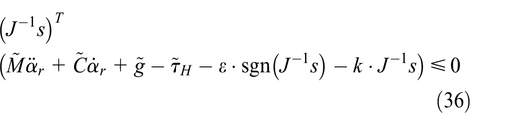
Let us define

Consequently,

Similarly, if

Consequently,

Considering equations (38) and (40), let

If
Experimental
This section presents the results of experiments performed to verify the proposed CVM and CVM-ASMC via HITUWV. The designed controller CVM-ASMC is compared with the conventional PID controller and model-based proportional–integral–derivative (MPID) controller during experimental studies.
As shown in Figure 5(a), the SFP is a rectangle-shaped pool, typically 10 m in depth with the bottom 5 m equipped with storage racks to hold fuel assemblies from the reactor.

Experimental set-up. (a) The photograph of SFP. A rectangle-shaped pool, typically 30 m in length, 10 m in width, and 10 m in depth. (b) Remote inspection on the ground control box. The ground control box consists of a high-performance computer, input devices, display devices, an optical transmitter, and a high-power supplier. (c) The screenshot of the control program. (d) The HITUWV is working in the SFP. (e) The welding experiments. Inset: weld metal after welding.
HITUWV has a maximum moving speed of 0.2 m/s and a maximum rotational speed of 0.26 rad/s. Testing experiments were performed in the SFP to evaluate the performance of the designed HITUWV as presented in Figure 5(b)–(d).
In the experiments, the control sampling interval time is selected as 0.1 s. The parameters of CVM-ASMC are designed as shown in Table 1.
Parameters of CVM-ASMC.

CVM-ASMC: centroid variability model–based adaptive sliding model controller.
In addition to the proposed controller, a PID controller and an MPID controller are designed for comparing the control performance. According to the servo tuning method,
23
the parameters of the PID controller are designed as
To investigate the stability of the CVM-ASMC during the movements of the 3-DOF manipulator, three sets of comparisons were carried out as shown in Figure 6. Tracking errors of the three controllers including PID, MPID, and CVM-ASMC are compared in the three cases of only X-axis moving, only Y-axis moving, and both X-axis and Y-axis moving. The case of X-axis moving is shown in Figure 6(a), where the X-axis of the 3-DOF manipulator moves to 100-mm position from 4.7 to 12.0 s, then moves back to 0 mm from 13.8 to 20.0 s. The case of only Y-axis moving, as shown in Figure 6(b), is similar to that of only X-axis moving. The Y-axis moves to 100-mm position from 2.5 to 10.0 s and then moves back to 0 mm from 12.6 to 19.8 s. As shown in Figure 6(c), in the case of both the X-axis and Y-axis moving, the X-axis moves to 100-mm position from 2.5 to 7.5 s and then moves back to 0 mm from 15.0 to 18.2 s. And the Y-axis moves to 100-mm position from 2.5 to 11.8 s and then moves back to 0 mm from 12.0 to 21.6 s.

The trajectories of the linear guides in three cases of (a) only X-axis moving, (b) only Y-axis moving, and (c) both X-axis and Y-axis moving.
Experimental results are displayed in Figures 7 and 8. The first columns of the two figures describe the experiments in the case of X-axis moving. The second columns of the two figures describe the experiments in the case of Y-axis moving. And the last columns of the two figures describe the experiments in the case of both X-axis and Y-axis moving.

The position stability evaluation of the HITUWV during the movements of the 3-DOF manipulator. The experiments compare average tracking errors of the three controllers (PID, MPID, and CVM-ASMC) in three cases as shown in Figure 6. (a)–(c) Average tracking errors in x of the three controllers. (d)–(f) Average tracking errors in y of the three controllers. (g)–(i) Average tracking errors in z of the three controllers.
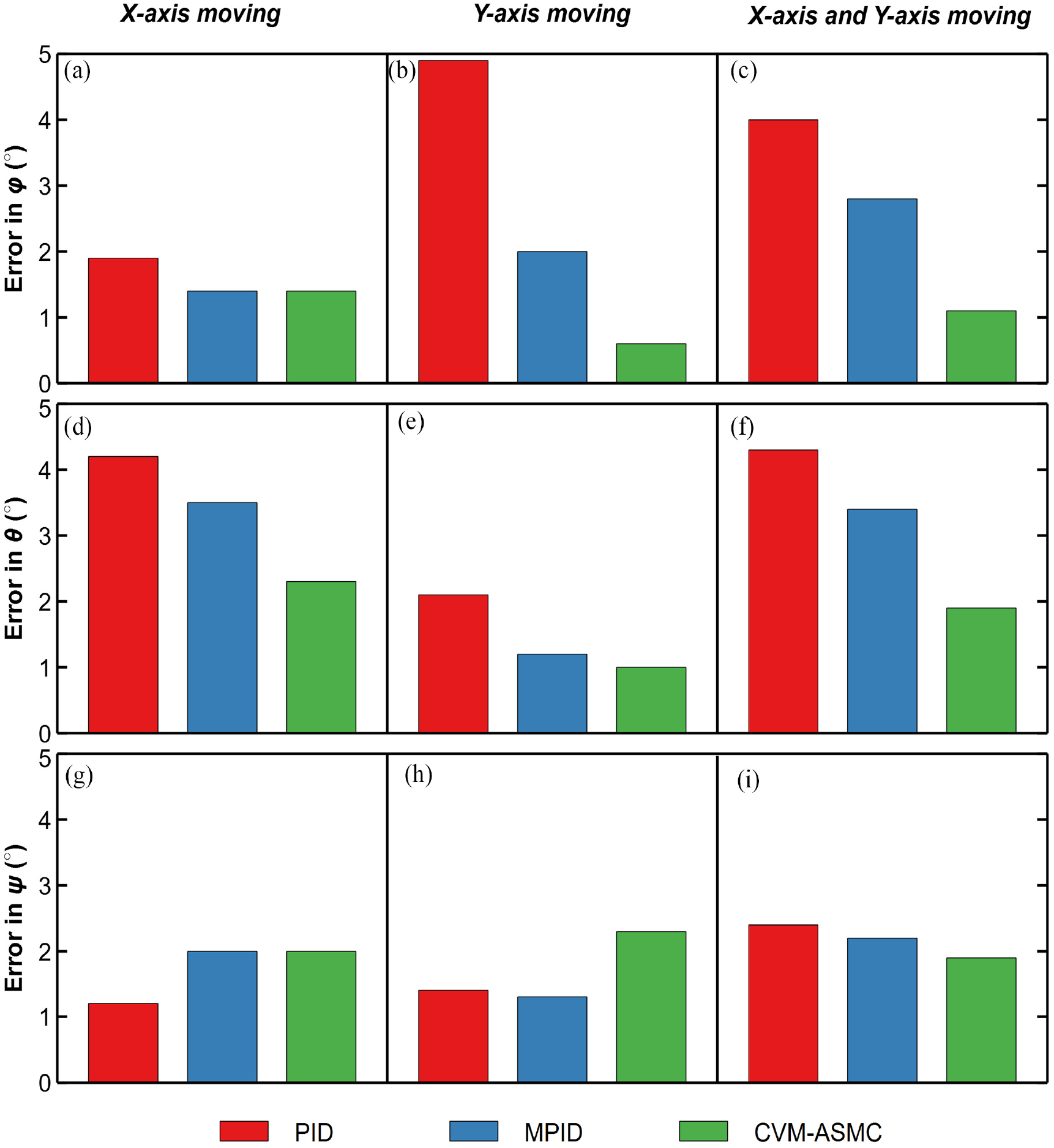
The attitude stability evaluation of the HITUWV during the movements of the 3-DOF manipulator. The experiments compare average tracking errors of the three controllers (PID, MPID, and CVM-ASMC) in three cases as shown in Figure 6. (a)–(c) Average tracking errors in
As shown in Figure 7(a)–(f), the tracking errors of the three controllers in x and y are almost zero and all the three controllers perform well that tracking errors remain bounded with 2 mm. As shown in Figure 7(g)–(i), the CVM-ASMC performs better than MPID and PID with an average error value of 3.2 mm and the PID performs worst with an average error value of 4.6 mm.
As shown in Figure 8(a)–(c), the tracking error of CVM-ASMC in
Note that, from Figures 7(i) and 8(c) and (f), due to the lack of CVM, the tracking error of the PID controller generates periodic oscillations in the case of both X-axis and Y-axis moving. Moreover, the tracking error of MPID is larger than that of CVM-ASMC, and CVM-ASMC shows less overshooting and lower average error comparing with MPID. Thanks to the CVM feedforward, MPID and CVM-ASMC show better performance than the conventional PID controller.
In order to demonstrate the performances of the three controllers, average tracking errors of PID, MPID, and CVM-ASMC are listed in Table 2. The tracking error of CVM-ASMC in most of the channels is less than those of PID and MPID. Experimental results suggest that the CVM-ASMC can meet the stability requirements of automatic underwater welding with enhanced stability and accuracy in SFP.
Average tracking errors of PID, MPID, and CVM-ASMC.

PID: proportional–integral–derivative; MPID: model-based proportional–integral–derivative controller; CVM-ASMC: centroid variability model–based adaptive sliding model controller.
Note: The bold values represent the best result among the three controllers.
To validate the energy consumption of CVM-ASMC, control outputs of the three controllers are presented in Figure 9. Because the control outputs of the three controllers in x, y, and

The control outputs of PID, MPID, and ASMC. The experiments compare control outputs of the three controllers (PID, MPID, and ASMC) in three cases of only X-axis moving, only Y-axis moving, and both X-axis and Y-axis moving. (a)–(c) Average torques in
To provide a more explicit description of the energy consumptions, the average powers of the three controllers are presented in Figure 10. During 10 trials, in the cases of only X-axis moving and only Y-axis moving, the average powers of the three controllers are at the same level with the value of 250 W. Nevertheless, in the case of both X-axis and Y-axis moving, the average powers of CVM-ASMC and MPID are at the same level with about 250 W which are much lower than that of PID with 400 W. As shown in Figure 11, the statistics of average powers suggested that CVM-ASMC can achieve better control performance with lower energy consumption.

The average powers of PID, MPID, and CVM-ASMC in the case of (a) only X-axis moving, (b) only Y-axis moving, and (c) both X-axis and Y-axis moving during 10 trials.

The energy consumption statistics of PID, MPID, and CVM-ASMC in the cases of only X-axis moving, only Y-axis moving, and both X-axis and Y-axis moving.
Conclusion
In this article, a CVM-based controller of the HITUWV is proposed to complete automatic underwater welding with high stability and accuracy.
An accurate CVM is presented which can describe the dynamic characteristics of the HITUWV precisely. Thus, the CVM can be utilized as an accurate feedforward control for the controller.
Furthermore, a CVM-ASMC for the HITUWV is proposed which can perform accurate centroid variability compensation.
Experimental results demonstrate that the stability and accuracy of the proposed CVM-ASMC can meet the application requirements of automatic underwater welding. Consequently, the CVM-ASMC holds great potential on the control of underwater operations with high stability and accuracy.
Footnotes
Acknowledgements
The authors would like to thank the reviewers and editors for their constructive comments and suggestions, which have been valuable to improve this paper.
Handling Editor: James Baldwin
Declaration of conflicting interests
The author(s) declared no potential conflicts of interest with respect to the research, authorship, and/or publication of this article.
Funding
The author(s) disclosed receipt of the following financial support for the research, authorship, and/or publication of this article: This work was supported by the National Natural Science Foundation of China (Grant No. 61673138), the National Key Basic Research Development Plan Project (973) (No. 2013CB035502), and the Self-Planned Task of State Key Laboratory of Robotics and System (HIT; Grant No. SKLRS201804B).