
Abstract
This article proposes a modified sequential multilateration method for measuring three-dimensional coordinates. The measuring system consists of a single laser tracker and four relay targets whose relative positions have been pre-calibrated by the multilateration method. The laser tracker is fixed on three prescribed positions successively, and these positions can be calibrated by using the distances between the laser tracker and the four relay targets based on the multilateration principle. Subsequently, the three-dimensional coordinates of each under-test point can be determined by the three laser trackers’ positions based on the trilateration principle. This method is more flexible than previous multilateration methods for three-dimensional coordinate collection, especially if the measurement space is partially covered by other objects. The mathematical model of this method is established. Based on the Monte Carlo method, a series of computer simulations are performed to optimize the system arrangement by investigating the performances of the measuring system with different system arrangement, and an optimal system arrangement is finally obtained. Practical measurement is also conducted to demonstrate the validity of the proposed method by comparing with a reference coordinate measuring machine.
Keywords
Introduction
Three-dimensional (3D) coordinate measurement is widely used in industrial production and scientific research, such as quality inspection of work piece, surface reconstruction from point clouds and measurement of geometric error of machine tools.1–3 The coordinate measuring machine (CMM) is one of the most typical instruments for 3D coordinate measurement, and it is of high measuring accuracy. But, its measuring volume is restricted by the measuring range, and the samples to be measured must be fixed on the table of the CMM, so CMM is not suitable for geometric error measurement of machine tool and large-scale metrology.
Due to the capability of large-scale metrology, laser tracker is widely applied in large structure assembly, large structure inspection, reverse engineering and calibration of machine tools and so on.4–7 However, the laser tracker has relatively low accuracy in angular measurement, which limits the application of a single laser tracker in 3D coordinate measurement with high accuracy.
Multilateration principle which was derived from the measuring principle of global positioning system (GPS) is widely used for measuring 3D coordinate based on the laser tracker.8–11 It only makes use of the capability of accurate length measurement of laser tracker, while the angular measurement function is abandoned. As a result, the accuracy of 3D coordinate measurement is greatly improved. Many researchers have been devoted to studying the configuration of the measuring system in the multilateration principle, and the optimal configuration is found by considerable simulations and experiments.9,12–15 For example, T Takatsuji et al. 9 used multilateration principle to measure 3D coordinate and pointed out that the optimal arrangement is that the four laser trackers should be positioned at the four apices of a regular tetrahedron that covers the measurement volume. DF Zhang et al. 13 utilized the computer simulation technique to investigate the performances of the multilateration measuring systems with different system configuration, and finally several guidance for optimizing the practicable measurement applications are recommended. The optimized measuring system can meet the accuracy requirement of high precision inspection of free-form surface and error mapping of machine tools, and it even can be used to calibrate the CMMs.6,16–19 Compared to the conventional methods for geometric error component measurement of CMM and machine tools by using laser interferometer, the methods based on the multilateration principle is simple and of high efficiency, for it has no requirement of aligning equipment and highly skillful operators.
The multilateration principle is high-priced because no less than four laser trackers are required in the measuring system. Many researchers proposed a sequential multilateration method for measuring the 3D coordinates of target points by fixing a laser tracker at four different positions in turn.19–21 The cost of the measuring system is greatly reduced since only one laser tracker is required. But the repeatability of under-test points’ position which was provided by the machine tool will contribute to the overall uncertainty of the systematic self-calibration, especially for the geometric error measurement of machine tools, the performance of the sequential multilateration technique is seriously reduced by the positioning error of machine tools. 21 Although the accuracy of the sequential multilateration method is less than that of the multilateration method, it is still useful in practical application. The multilateration method has an optimized arrangement, which can benefit the accuracy of coordinate collection,6,9 but if the measurement space is covered by other objects, the optimized arrangement will not be achieved, so that the accuracy of coordinate collection will be damaged greatly.
Thus, a modified sequential multilateration method is studied in this article. Four relay targets are introduced into the measuring system of the sequential multilateration method to realize systematic self-calibration. The advantage of this modified method is that it is still effective even if the measurement volume is partially covered by other objects. Also, the four relay caves are stable (not moved), so that they will not introduce uncertainty into the measuring system. The rest of this article is arranged as follows: in section “Multilateration principle,” the multilateration principle is introduced. In section “Proposal of the modified sequential multilateration method,” the basic principle of the proposed method is introduced and the mathematical model of the measuring system is established. In section “Optimization of the systematic arrangement,” the computer simulation technique is applied to optimize the arrangement of the measuring system. In section “Experiments and analysis,” practical experiments are conducted to demonstrate the modified sequential multilateration method. Finally, the conclusion and summary are addressed in section “Conclusion.”
Multilateration principle
Laser tracker is a portable 3D coordinate measuring system for large-scale metrology based on the spherical coordinate system. But the accuracy of angle measurement is relatively lower than that of length measurement, which leads to more errors in 3D coordinate measurement. Furthermore, the accuracy of 3D coordinate measurement became lower with the increase in measuring distance. Thus, to get high accuracy of 3D coordinate measurement, the multilateration principle is developed by many researchers.6,9,12–15
First, the basic formula of the trilateration principle is introduced. As shown in Figure 1, the coordinates of three points, P1 (x1, y1, z1), P2 (x2, y2, z2) and P3 (x3, y3, z3) are already known, and an unknown target point P (x, y, z) will be measured. If the distances l1, l2 and l3 can be measured accurately, equation (1) can be established. The 3D coordinates of point P can be determined by solving this system of equations. The terms P and Pi in this paragraph is effective only for the illustration of Figure 1, not consistently used through the article. The P and Pi (i =1 ∼ 8) used in Table 1 are only effective for the simulation of the measurement uncertainty of the modified sequential multilateration method.


Schematic diagram of the trilateration principle.
Measuring errors obtained by simulation for arrangement (1).

Only length measurement is used in the trilateration principle, and the angle measurement with relatively low accuracy is abandoned, so that the accuracy of 3D coordinate measurement is greatly improved. However, the incremental length measurement accuracy of the interferometer embedded in the laser tracker is much better than the absolute length measurement accuracy. To realize higher accuracy of 3D coordinate measurement, the multilateration principle was developed by researchers, 6 as shown in Figure 2.

Schematic diagram of the multilateration principle.
Three laser trackers, S1, S2 and S3, are used to set up a measuring system. A reference coordinate frame, oxyz, is established, that is, let the origin locate at S1, let the x-axis pass through S2, let the x–y coordinate plane pass S3. The 3D coordinates of S1, S2 and S3 are (0, 0, 0), (xS2, 0, 0) and (xS3, yS3, 0), respectively. Thus, these three systematic parameters, xS2, xS3 and yS3, should be determined precisely while conducting the measurement. As shown in Figure 2, the fourth laser tracker, S4 (xS4, yS4, zS4) is involved in the measuring system to provide redundant information which enables the estimation of the six systematic parameters including xS4, yS4 and zS4. Because the incremental distance measurement which realized by interferometer embedded in the laser tracker is more accurate than the absolute distance measurement, a reference point P0 (x0, y0, z0) should be defined to provide a reference absolute distance (RAD) between P0 and each laser tracker. Thus, there are totally nine systematic parameters including x0, y0 and z0.
Similar to the trilateration principle, the RADs can be calculated by
where lj is the RAD between reference point and the jth laser tracker, j = 1, 2, 3, 4.
Assume there are n points under test, for each point P i (xi, yi, zi), i = 1, 2,…, n, four equations can be obtained

where Δlij is the incremental distance between point P i (xi, yi, zi) and the jth laser tracker relative to the RAD lj. Δlij can be measured accurately by using the laser tracker in practical application.
According to equations (2) and (3), there are totally 4(n + 1) equations with 3n + 13 unknowns. Thus, the inequation, 4(n + 1) ≥ 3n +13, that is, n ≥ 9 should be satisfied to guarantee that these equations have solution. Nonlinear least square method can be used to compute all the unknowns if n > 9. Hence, we can conclude that the necessary condition of successfully achieving all the systematic parameters and under-test point coordinates is that the number of points under test is no less than 10, including the reference point.
In fact, more laser trackers can be involved in the measuring system. Assume that there are m laser trackers and n under-test points, then the total number of equations is m(n + 1), and the number of unknowns is 3n + 13 + 4(m − 4). Thus, m(n + 1) ≥ 3n + 13 + 4(m − 4), that is, mn ≥ 3n + 3 m − 3 should be satisfied to guarantee that these equations have solution. Also, if mn > 3n + 3 m + 1, all the unknowns can be obtained by the nonlinear least square method.
In Wang et al., 20 a sequential multilateration method is developed. A single laser tracker is used to measure the 3D coordinates by locating the laser tracker at four different positions in turn. The mathematical model of this sequential multilateration method is similar to the multilateration method mentioned earlier. But the measurements at different laser-tracker-stations cause repeatability errors of the under-test points’ position, and this repeatability will produce contribution to the overall uncertainty of the systematic self-calibration, so that the measurement accuracy is damaged seriously.
Proposal of the modified sequential multilateration method
A modified sequential multilateration method for 3D coordinate collection
In Umetsu et al., 6 an optimized arrangement of the laser trackers in the multilateration method is given as illustrated in Figure 3, the four laser trackers should cover the measurement volume which the measurement points are allocated in.

The optimized arrangement of the laser trackers in the multilateration method.
But the optimized arrangement cannot be realized when the measurement volume is partially covered as shown in Figure 4, and then the accuracy of coordinates collection will be damaged greatly.

The measurement volume is partially covered.
In order to solve this problem and reduce the cost simultaneously, a modified sequential multilateration method is developed in this article. The measuring system consists of one laser tracker and four relay targets O, Q, K and P0, as shown in Figure 5. The relative positions of these four relay targets can be pre-calibrated by the multilateration principle shown in Umetsu et al. 6 and Schwenke et al. 19 Then, a reference coordinate frame is established: let O be the origin of the reference coordinate system, let the x-axis pass through point Q and the x–y coordinate plane pass through point K. The coordinates of O, Q and K are (0, 0, 0), (xQ, 0, 0) and (xK, yK, 0), respectively. The fourth point P0 (x0, y0, z0) is a reference point, which can provide RADs for the modified sequential multilateration method.

Schematic diagram of the time-sharing multilateration principle.
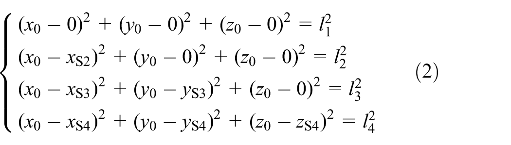
The measurement procedure can be divided into three steps. In each step, the laser tracker is fixed on position S j , j = 1, 2, 3. By using the multilateration principle, four equations can be obtained

where xO = 0, yO = 0, zO = 0, yQ = 0, zQ = 0, zK = 0, lj is the RAD between reference point P0 and the position of laser tracker S j , ΔlOj, ΔlQj and ΔlKj are the incremental distances between S j and O, Q, K relative to the RAD. These incremental distances can be accurately tested by laser tracker. (xSj, ySj, zSj) and lj can be obtained by solving equation (4).
In the meantime of establishing equation (4), Δlij, the incremental distance between the under-test point P i (xi, yi, zi) and S j relative to the RAD can also be measured by laser tracker. Then, we can obtain equation (5)

The laser tracker is located at three different positions S j in turn, that is, j = 1, 2, 3 in equations (4) and (5). After the three-step measurements, totally three equations are obtained from equation (5). Equation (5) can also be transformed into equation (6) as follows

The coordinates of under-test point P i , (xi, yi, zi) can be achieved by solving equation (6).
Optimization of the systematic arrangement
Length measurement accuracy of laser tracker
The length measurement accuracy of the laser tracker would produce a great contribution to the overall accuracy of the sequential multilateration method. The approach mentioned in Umetsu et al. 6 is conducted to verify the accuracy of the FARO laser tracker used in this article. The verification is realized by comparing the laser tracker with a high precision reference CMM of which maximum permissible error, according to the manufacturer’s catalogue, is (0.9 + l/333) μm, where l is CMM’s displacement in the measurement procedure. In this verification, eight target points are arranged to form a circle with diameter being 300 mm, and the distance between these points and the laser tracker is approximately 1 m. The distance between the laser tracker and a reference point is considered as RAD, and the incremental length between each point and laser tracker relative to the RAD can be tested by the laser tracker. The nominal coordinates of each target point can be tested by the reference CMM. The self-calibration is applied to obtain the coordinate of laser tracker’s position and the absolute distances between all the target points and the laser tracker. This experiment is repeated 20 times, and the maximum deviation and the repeatability are found to be 0.807 and 0.334 μm, respectively.
Optimization of the arrangement of the modified sequential multilateration method
Different arrangements of the measuring system
The measuring system is made up of four relay targets and one laser tracker, which must be sequentially fixed on three stations, in other words, there are totally seven stations in the measuring system. Seven points can define a cube. Thus, the typical arrangements can be that the four relay targets and the three laser tracker stations are, respectively, located at the corners of the cube, which covers the measurement volume. The coordinate frame is defined by the three relay targets O, Q and K; therefore, the positions of these three relay targets in different arrangements should be same to each other. The interchangeability of the three laser tracker’s stations and the symmetry of the systematic arrangement should also be considered. Thus, as shown in Figure 6, there are totally 13 arrangements of the measuring system for this modified sequential multilateration method.

The 13 arrangements of the proposed measuring system.
Probability distribution of the 3D coordinate measurement uncertainty
The Monte Carlo simulation technique is applied to investigate the performance of the proposed measuring system. It is assumed that the probability distributions of all the uncertainties follow the normal distribution. As mentioned in the previous section, the laser tracker’s maximum deviation of the length measurement error is about 0.807 μm, and thus, a normal distribution is assigned to these incremental lengths with expectation being zero and standard deviation being 0.269 μm. The simulation is divided into two steps. The first step is to simulate the position error of the four relay targets P0, O, Q and K, and the second step is to simulate the 3D coordinate measurement uncertainty of the modified sequential multilateration method.
The computer simulation of the position errors of the relay targets
As shown in Figure 3, the four relay targets may locate at the four of the eight vertices of the measurement volume. The flow chart of computer simulation of the position errors of the eight vertices of the measurement volume is shown in Figure 7.

The flow chart of computer simulation of the position errors of the relay targets.
Thereinto, the ideal parameters in Figure 3 are given as follows. The length of cubic where the laser trackers locate in is a = 2000 mm, The length of cubic of measurement volume is b = 1000 mm, and the coordinates of the stations are LT1(0, 0, 0), LT2(2000, 0, 0), LT3(1000, 0, 1000
The simulation results indicate that the measurement errors of measurement points A, B, C, D, E, F, G and H approximately follow the normal distribution. Take point A as example, the probability density function (PDF) curve of ΔxA is shown in Figure 8(a), and the maximum deviation of the coordinates of all the measurement points is given in Figure 8(b). Δx denotes the measurement error of x-coordinate, Δy denotes the measurement error of y-coordinate and Δz denotes the measurement error of z-coordinate. The maximum deviation of Δx is 1.398 μm, the maximum deviation of Δy is 1.413 μm and the maximum deviation of Δz is 1.395 μm.

The simulation results for the measurement points A, B, C, D, E, F, G and H: (a) the PDF of measurement errors Δx of point A and (b) the maximum deviation of all the measurement points.
2. The computer simulation of the measurement uncertainty of the modified sequential multilateration method
Taking arrangement (1) in Figure 6 as an example, the Monte Carlo simulation technique will be performed to compute the coordinate measurement errors of points P1 (100, 100, 100), P2 (900, 100, 100), P3 (100, 900, 100), P4 (900, 900, 100), P5 (100, 100, 900), P6 (900, 100, 900), P7 (100, 900, 900) and P8 (900, 900, 900), respectively, in the new coordinate frame defined by the three relay targets O, Q and K. In the simulation, the side length of the cube, L is set to be 1000 mm, and according to the simulation results of position errors of the relay targets, the maximum deviation of Δx, Δy and Δz are 1.398 1.413 and 1.395 μm, respectively. Thus, random errors following normal distribution are assigned to the coordinates of P0, O, Q and K with expectation being zero and standard deviation being 0.466, 0.471 and 0.465 μm for Δx, Δy and Δz. The random errors of the incremental lengths are still the normal distribution with expectation being zero and standard deviation being 0.269 μm. The number of simulation trials is 10,000. The flow chart of this computer simulation is shown in Figure 9.

The flow chart of the computer simulation of the modified sequential multilateration method.
The simulation results indicate that the PDF curves of the 3D coordinate measurement errors of P1 to P8 approximately follow the normal distribution too. The statistical parameters of the 3D coordinates’ measurement errors of P1 to P8 are tabulated in Table 1.
The uncertainty of x-coordinate measurement of point P5 is better than that of other points, and the maximum deviation is just 0.787 μm; the uncertainty of x-coordinate measurement of point P6 is worse than that of other points, and the maximum deviation is 1.785 μm; the uncertainty of y-coordinate measurement of point P5 is better than that of other points, and the maximum deviation is just 0.586 μm; the uncertainty of y-coordinate measurement of point P6 is worse than that of other points, and the maximum deviation is 2.167 μm; the uncertainty of z-coordinate measurement of point P2 is better than that of other points, and the maximum deviation is just 0.697 μm; the uncertainty of y-coordinate measurement of point P4 is worse than that of other points, and the maximum deviation is 2.012 μm.
Comparison of all the 13 arrangements
The measurement errors of points P1 (100, 100, 100), P2 (900, 100, 100), P3 (100, 900, 100), P4 (900, 900, 100), P5 (100, 100, 900), P6 (900, 100, 900), P7 (100, 900, 900) and P8 (900, 900, 900) are simulated in the every 13 arrangements shown in Figure 6 by using the Monte Carlo method. The side length of cube is L = 1000 mm too, and the number of simulation trials is also 10,000.
The simulation results indicate that the simulation results of every arrangement are similar to each other; the PDF curves of each under-test points’ 3D coordinate measurement errors are still approximately following the normal distributions.
In order to compare the measurement results of different arrangements and determine which one is the optimal arrangement, several definitions are introduced as follows:
Δ xij : the maximum x-coordinate measurement error of point P j in arrangement (i), where j = 1, 2,…, 8, i = 1, 2,…, 13.
ΔxiM: the maximum value of maximum x-coordinate measurement error of all the points in arrangement (i), that is, ΔxiM = MAX(Δ xij ), where j = 1, 2,…, 8, i = 1, 2,…, 13.
ΔxiE: the mean value of maximum x-coordinate measurement error of all the points in arrangement (i), that is, ΔxiE = AVERAGE(Δ xij ), where j = 1, 2,…, 8, i = 1, 2,…, 13.
The definitions of Δ yij and Δ zij are similar to Δ xij . The definitions of ΔyiM and ΔziM are similar to ΔxiM. The definitions of ΔyiE and ΔziE are similar to ΔxiE.
First, the maximum values of maximum 3D coordinate measurement error of all the points in each arrangement are compared, that is, ΔxiM, ΔyiM and ΔziM in each arrangement are compared. As shown in Figure 10(a)–(c), and obviously ΔxiM, ΔyiM and ΔziM of arrangements (1) and (4) are better than that of other arrangements.

Comparison for each arrangement: (a) ΔxiM of each arrangement, (b) ΔyiM of each arrangement, (c) ΔziM of each arrangement, (d) ΔxiE of each arrangement, (e) ΔyiE of each arrangement and (f) ΔziE of each arrangement.
Second, the mean values of maximum 3D coordinate measurement error of all the points in each arrangement are compared, that is, ΔxiE, ΔyiE and ΔziE in each arrangement are compared. As shown in Figure 10(d)–(f), similar to the comparison of ΔxiM, ΔyiM and ΔziM, the conclusion is that arrangements (1) and (4) can be considered as the optimal arrangements.
To compare the measurement results of arrangement (1) and (4) more clearly, the maximum values and mean values of maximum 3D coordinate measurement error of arrangements (1) and (4) are tabulated in Table 2. The measurement results of arrangement (1) are slightly more satisfied than that of arrangement (4). Moreover, in arrangement (1), the reference point P0 locates near points O, Q and K, which can make the measurement easy to be implemented in practical application. Thus, arrangement (1) is finally considered as the optimal arrangement in this article.
Comparison of simulation results of arrangements (1) and (4).

Simulation for other arrangements
In practice, part of the seven stations, including relay targets and laser tracker positions, can also locate at the sides of the cube which covers the measurement volume. A typical arrangement of this case is shown in Figure 11. P0, Q, K, S0, S1 and S2 are fixed on the midpoint of the cube’s side. Monte Carlo simulation is performed to compute the 3D coordinate measurement errors of points P1 (100, 100, 100), P2 (900, 100, 100), P3 (100, 900, 100), P4 (900, 900, 100), P5 (100, 100, 900), P6 (900, 100, 900), P7 (100, 900, 900) and P8 (900, 900, 900), respectively. In the simulation, L is set to be 1000 mm, and the number of simulation trials is 10,000. The simulation results indicate that the PDF curves of all the 3D coordinate measurement errors approximately follow the normal distribution. A comparison simulation is performed between the arrangement 11 and the arrangement (1) in Figure 6, and the simulation results are illustrated by Figure 12. So we can definitely conclude that the measurement results of arrangement (1) in Figure 6 are greatly better than that of arrangement in Figure 11. Series of simulations have been performed for the arrangements of which not all the stations locate at the corners, and the measurement results can entirely validate that the performances of these arrangements are worse than that of arrangement (1) in Figure 6. Thus, we can conclude that arrangement (1) in Figure 6 is the optimal arrangement.

Not all the stations locate at the corner of measurement volume.

Experiments and analysis
To verify the effectiveness of the proposed sequential multilateration method, a reference CMM is used to conduct a comparison experiment, as shown in Figure 13. In this experiment, the retroreflector which is fixed on the CMM’s moving head is moved to the grid points in a cube whose side length is 300 mm, and the step length is 150 mm. Thus, there are 27 grid points under test in all. The maximum permissible error of the CMM is (0.9 + L/333) μm. Since the CMM is a reference, the error of CMM is considered as zero, and the measurement errors in this experiment are considered to be only induced by the proposed modified sequential multilateration method. The experiment is repeated 10 times, and the experiment results are illustrated in Figure 14.
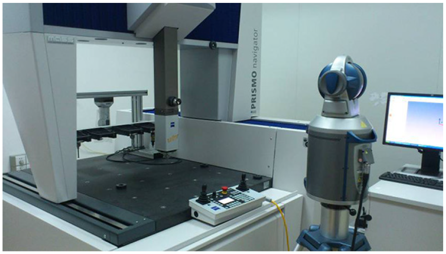
The experimental setup.

The measuring results of the proposed sequential multilateration method: (a) maximum deviation of the measurement results of each point and (b) standard deviation of the measurement results of each point.
According to the experimental results, the maximum deviations of x, y and z are 2.65, 2.43 and 2.68 μm, respectively; the repeatabilities of x, y and z which are quantified by standard deviations with respect to the number of trials are all less than 0.74, 0.78 and 0.86 μm. The accuracy of the experimental measurement is relatively lower than that of the measurement in simulation because of the operation errors.
Conclusion
A modified sequential multilateration method based on the laser tracker is proposed to measure coordinates of spatial points. The mathematical model of this method is established. The computer simulation technique is applied to optimize the arrangement of the measuring system by estimating the PDF of the 3D coordinate measurement errors, and an optimal arrangement is achieved finally. The simulation results indicate that the error of 3D coordinate measurement is less than 2.167 μm if the length measurement error of the laser tracker does not exceed 0.807 μm. A CMM is used as a reference to verify the effectiveness of this proposed modified sequential multilateration method and the measurement errors of x-coordinate, y-coordinate and z-coordinate verified by the experiments are less than 2.65, 2.43 and 2.68 μm, respectively. Moreover, if the measurement is repeated 10 times, the measurement accuracies can be greatly improved by averaging the measurement results.
The accuracy of the modified sequential multilateration method reported in this article is relatively lower than that of the conventional multilateration principle, but the cost is greatly reduced because of utilizing only one laser tracker in the measuring system. In addition, this method is more useful than previous multilateration methods if there are barriers between the laser trackers and the measurement space. This method can meet the accuracy requirements of some applications, such as geometric error component measurement of machine tools and inspection of large-scale surface.
Footnotes
Handling Editor: James Baldwin
Declaration of conflicting interests
The author(s) declared no potential conflicts of interest with respect to the research, authorship and/or publication of this article.
Funding
The author(s) disclosed receipt of the following financial support for the research, authorship and/or publication of this article: This research was supported by the Shenzhen Science and Technology Plan Project (grant nos GRCK2016041511185978, JCYJ20170817112445033 and GJHZ20180416164715805), Shenzhen Institute of Information Technology Research Project (grant no ZY201708) and Engineering Applications of Artificial Intelligence Technology Laboratory of Shenzhen Institute of Information Technology (grant no PT201701).