
Abstract
Introduction
Laser tracker is a portable three-dimensional measurement system and is widely used in various fields such as the aviation, aerospace, automotive, and shipbuilding areas due to the high measurement accuracy and efficiency. 1 Many products with large external dimensions, especially in the aerospace industry, are generally measured with the requirement of high measurement accuracy. However, as an optical measurement device, laser tracker has a common disadvantage of optical measurement devices; that is, the measurement accuracy is significantly reduced with the increase in the measurement distance. 2 It is noted that station-transfer measurement of laser tracker technique would be used in the large-scale measurement. 3 However, the station-transfer measurement needs coordinate transformation in which an accumulated error can be caused, while the measurement accuracy cannot be significantly improved and even be occasionally reduced. Larger measurement errors can hardly meet the high-precision measurement requirement of modern industrial products.
Many research works have been studied about the improvement of the measurement accuracy of large-scale products. Calkins established a unified spatial measurement network model for multiple measurement devices and optimized the parameters of each device in the measurement process. 4 Based on the measurement covariance matrix and Jacobi matrix of the measurement equipment, Mitchell et al. 5 improved the precision of data coordinate transformation between measurement devices by taking the matrix-weighted linear minimum variance as the optimal fusion criterion. Predmore 6 proposed a method based on the minimum Mahalanobis distance of reference points to improve the measurement accuracy of large-scale measurements based on the error-ellipsoid-based uncertainty model of the measurement point. It can be seen that these methods are to optimize configuration of the combined measurements of multiple devices based on the measurement system to improve the accuracy of large-scale measurement.
In order to improve the measurement accuracy of measurement points, this paper introduces the photogrammetry system in the large-scale measurement process by the laser tracker. The photogrammetry has the characteristics of high accuracy, high efficiency, and strong portability and it has been widely used in many industrial areas, such as aerospace manufacturing, robot calibration, and pipeline measurement.7–11 We have used the photogrammetry system to measure the point farther away from the laser tracker to obtain a measurement value with relatively high accuracy and utilized the coordinate correction method based on the Rodrigues rotation formula to correct the measured value by the laser tracker to improve the measurement accuracy of the large-scale product.
The measurement accuracy analysis of the laser tracker
The spherical coordinate system is usually used for laser tracker system and the coordinate system can be seen in Figure 1.
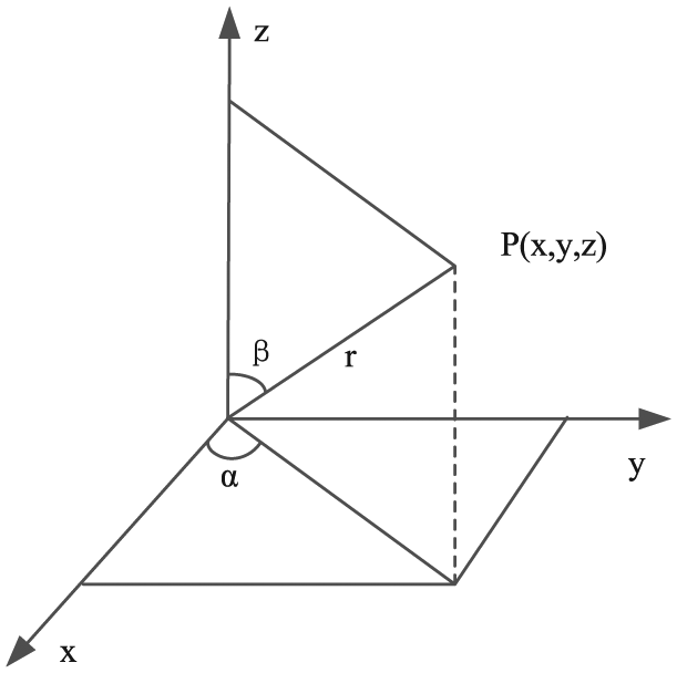
The spherical coordinate system for laser tracker.
It can be clearly seen that the coordinate (x, y, z) of any point
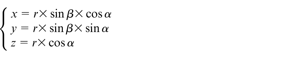
By linearizing the above equation, the error at point
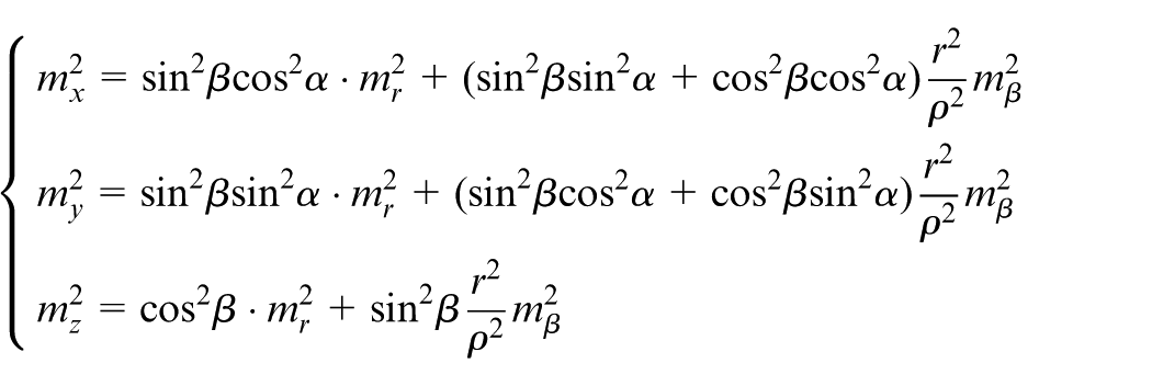
Furthermore, the accuracy of plane coordinates and space coordinates of point
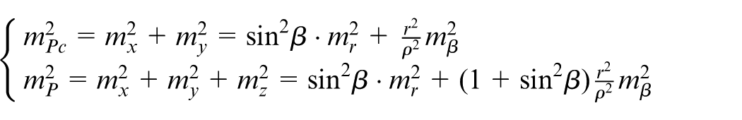
According to the above equations and relevant data, the errors of the nominal angle of the Leica AT901-B laser tracker and the IFM measurement are as follows 14
The measurement error of actual point of the Leica AT901-B laser tracker should be

where the coefficient k should be between 1.2 and 1.3. 15
It can be seen that the measurement error of the laser tracker increases linearly with the increase in the measurement distance, indicating that the measurement error should be larger when measuring an object far away from the laser tracker. Therefore, a method based on photogrammetry system has been proposed to improve the large-scale measurement accuracy of laser tracker. The photogrammetry system with good portability and high precision has been facilitated to perform measurements on test points far away from the laser tracker, thereby achieving the higher accuracy. With the assistance of photogrammetry and the coordinate correction method based on the Rodrigues rotation formula, the measurement results of the measurement point in the laser tracker are corrected, and the measurement accuracy of the laser tracker for the long distance point is improved. Figure 2 shows the schematic diagram of the photogrammetry and laser tracker in large-scale space measurement.
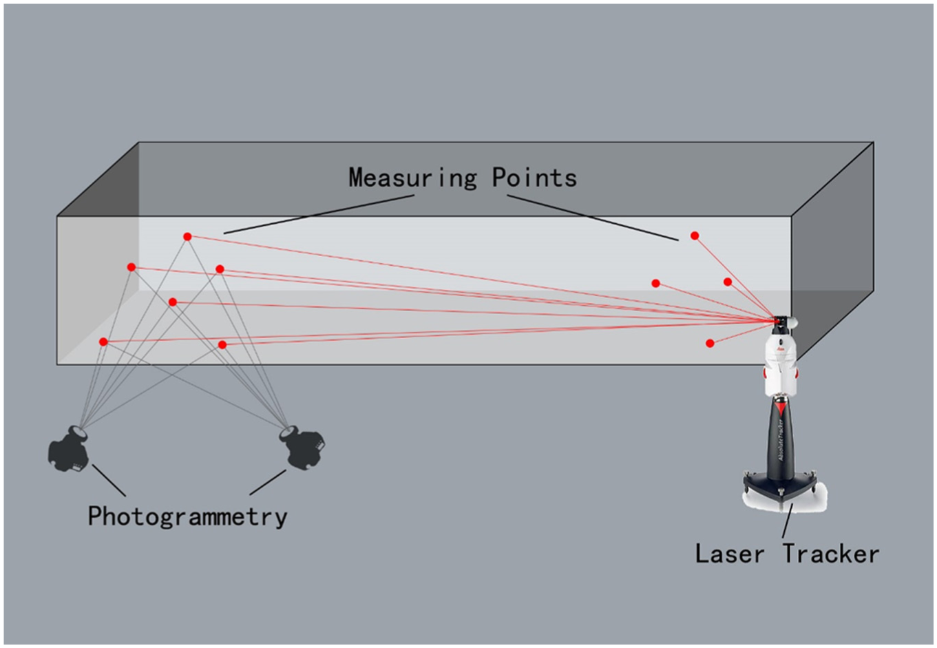
Schematic diagram for the improvement on large-scale measurement accuracy of laser tracker based on photogrammetry.
The coordinate correction method based on Rodrigues’ rotation formula
The coordinate systems of the photogrammetry system and laser tracker can be represented as
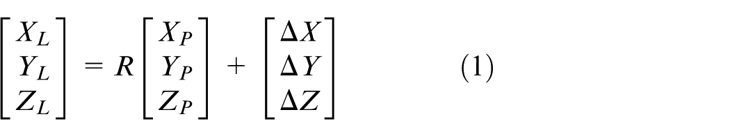
where
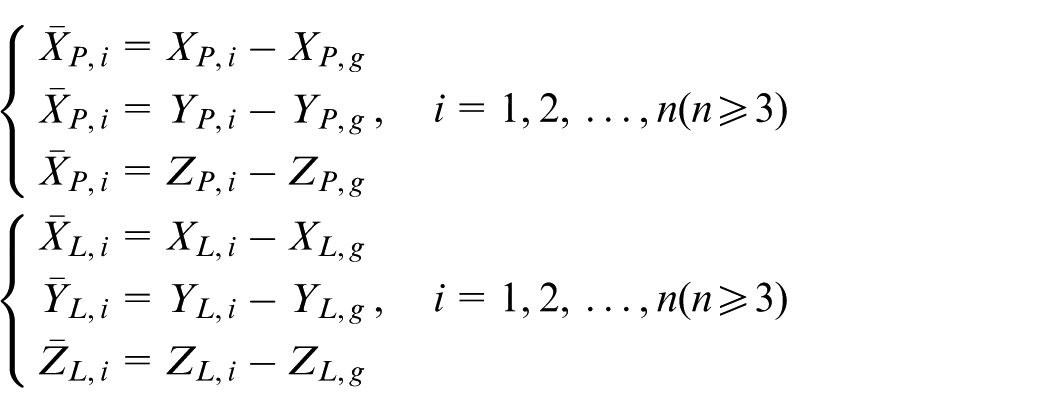
First, the common points are measured using the photogrammetry and laser tracker. The common points measured by the photogrammetry system are
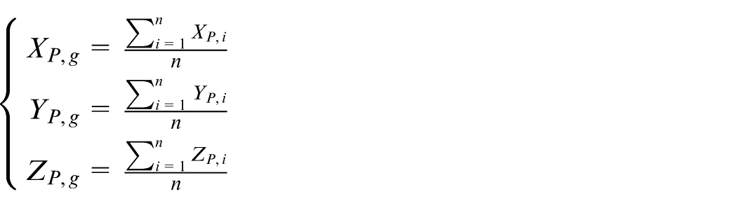
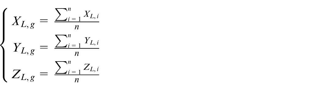
After the processing based on the center of gravity method, the coordinates measurement results of the photogrammetry and laser tracker have also been changed and can be denoted as
From equation (1), the following equation can be obtained
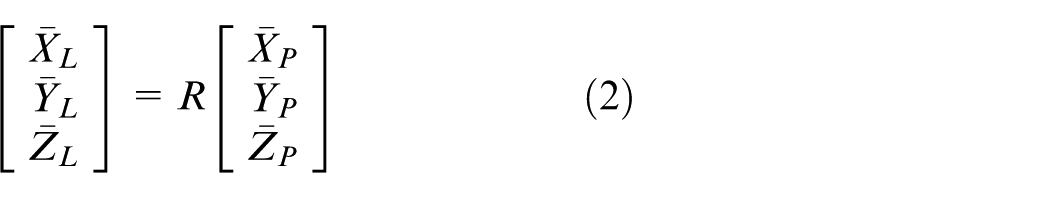
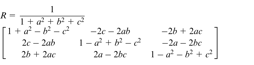
According to the Rodrigues rotation formula, an antisymmetric matrix can be assumed
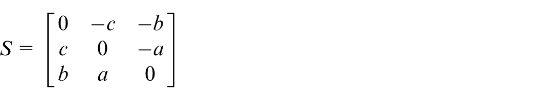
where a, b, and c are Rodrigues’ parameters, then the rotation matrix

That is
Therefore, the rotation matrix can be obtained by calculating a, b, and c. From equation (2), the following equation can be obtained
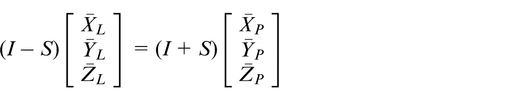
Expanding and simplifying the above equation, we can obtain the following
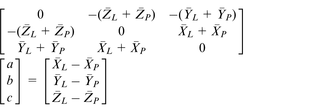
During actual measurement process, since measurement points have huge number, the number of equations formed by these points is much larger than the number of unknowns. Therefore, adjustment calculation becomes necessary. The number of measurement points is set to N. It can be obtained that
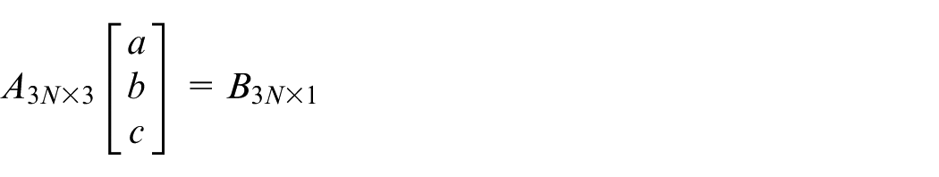
where
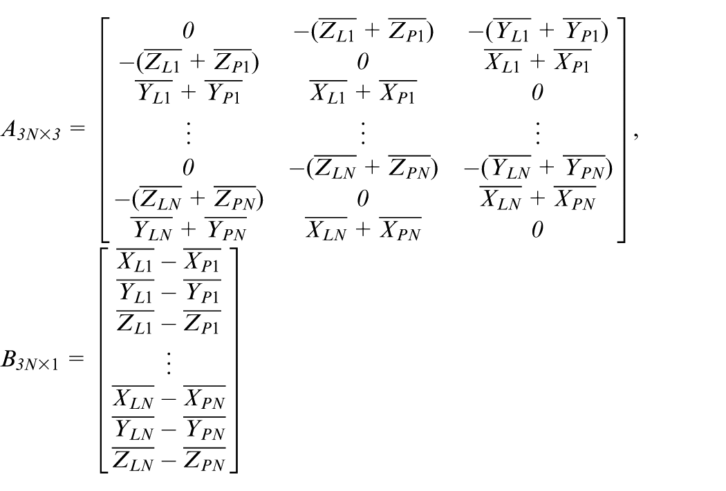
It can be assumed that

With the principle of least squares, the following can be obtained as follows

The above equation is actually a ternary linear equation system, where the exact solutions of a, b, and c can be easily solved. From equation (1), the rotation matrix
The obtained rotation matrix
Large-scale object measurement procedures based on Rodrigues’ rotation formula correction method
Measurement environmental control. Before carrying out the measurement of the laser tracker, the measurement environment needs to be controlled, including stopping the equipment that can cause vibration, selecting suitable lighting conditions, selecting the appropriate temperature, and shielding the reflective object in the measurement environment, and so on, which can deeply ensure the measurement accuracy.
Test points selection. The test points of the object should be confirmed, and the target ball seats would be installed on these test points where it is used to place the target balls of the laser tracker and the photogrammetry system during the measurement process.
Position selection of object and station selection of measurement instruments. According to the actual situation of the measurement environment, the position and height of the object need to be adjusted so that the test points would not be blocked by other objects and can be easily measured. According to the position of the object, the station position of the laser tracker could be determined so that it can directly measure all test points. If tested points are distributed in a large space, the laser tracker should be arranged as close as possible within the area where more points needs to be measured. After determining the station of the laser tracker, the position of the photogrammetry system could be determined which should be in the area where the points to be measured are far from the laser tracker.
Measurement of laser tracker. The laser tracker is placed on the station determined by step 3. After placing the target balls on the target ball seats of each test point, the laser tracker is used to measure each the target ball to obtain the coordinates of every test point in the laser tracker coordinate system.
Measurement of photogrammetry system. The photogrammetry system is placed at the selected position. The target balls with the reflective mark on the target ball seats which are far away from the laser tracker will be measured by photogrammetry system. The photogrammetry system is used to take several photographs at the measurement points in different positions and in different directions. The image processing software is used to process and calculate the photographs to obtain the coordinates of these points in the photogrammetry system coordinate.
Data correction and processing. Due to the measurement mechanism of the laser tracker, the errors become larger with the increase in measurement distance. Compared to laser tracker, the photogrammetry system is closer to those points which have larger errors. In addition, the measurement accuracy of the photogrammetry system is comparable to that of the laser tracker, and actually the better photogrammetry systems have higher measurement accuracy than the laser tracker does. Therefore, compared to the errors in the measurement by laser tracker, the errors by the photogrammetry system are relatively small.
Because the coordinates obtained by the photogrammetry system and the laser tracker are not in the same coordinate system, the coordinate correction algorithm based on the Rodrigues rotation formula can be used to transform the result of the photogrammetry system coordinate system into the laser tracker coordinate system, thereby replacing the measurement results of laser tracker to accomplish the correction process. The flow chart of the large-scale object measurement procedure based on the Rodrigues rotation formula coordinate correction method is shown in Figure 3.
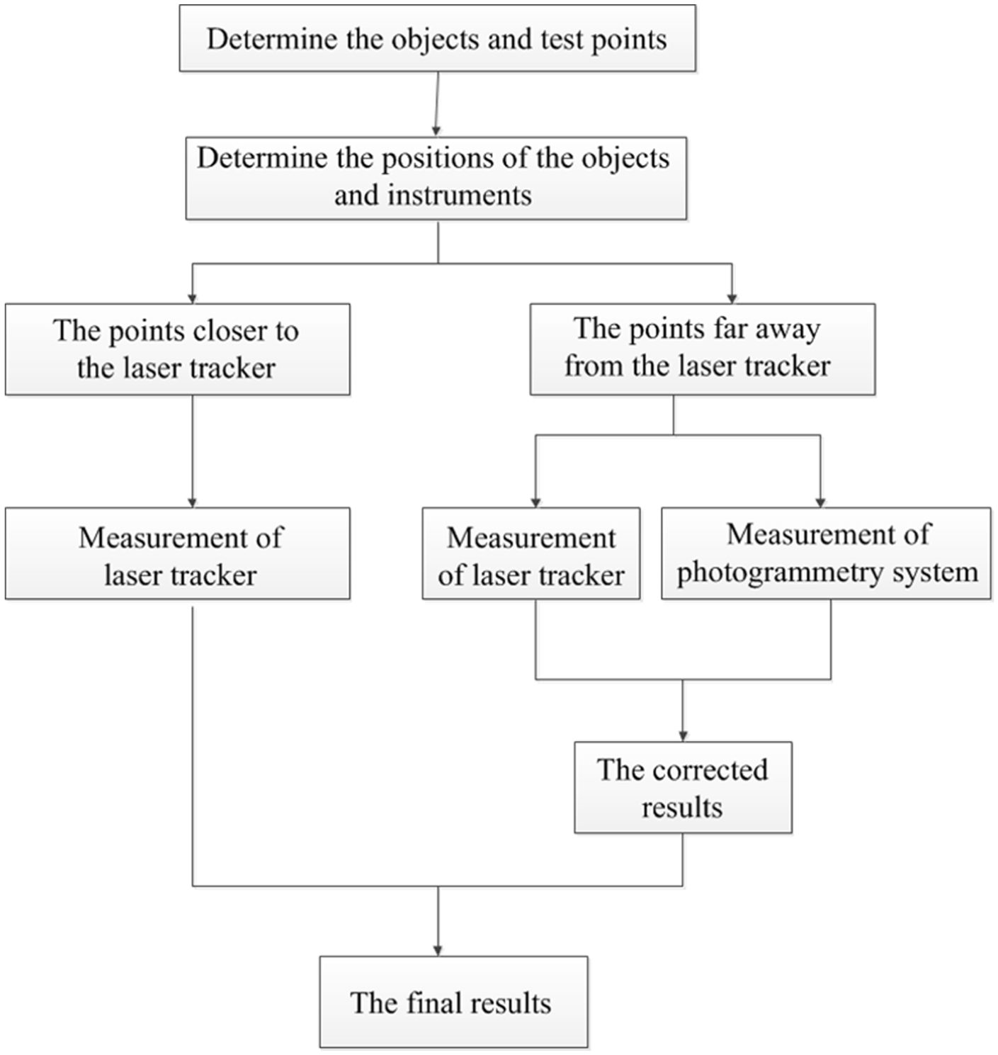
The flow chart of the large-scale object measurement procedure based on the Rodrigues rotation formula coordinate correction method.
Experiment
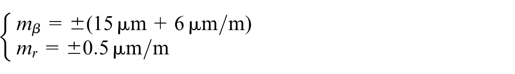
In this paper, the feasibility of the large-scale coordinate measurement method based on photogrammetry has been demonstrated, and its measurement accuracy has been analyzed. The experiment used laser tracker assisted by photogrammetry to carry out the large-scale coordinate measurement. The photogrammetry system is a V-STARS/S8 single-camera measurement system developed by GSI of the United States. The nominal measurement accuracy of the system is
This experiment mainly validates the error when the photogrammetry-assisted laser tracker measures the distant points; therefore, when measurement system has been arranged, the measurement points closer to the laser tracker are no longer arranged. In the experimental space, three reference rulers which are made of Invar alloy steel are arranged whose coefficient of thermal expansion is very low and whose length can remain constant over a wide range of temperatures. The length of reference ruler has been calibrated with a more accurate measurement device before it leaves the factory; thus, the length of the reference ruler can be used as an actual value.
The laser tracker station is determined to be located at a distance of approximately 7–9 m from the reference ruler to ensure that the laser tracker can directly measure both ends of each reference ruler. The positions of several photogrammetry systems are determined at a distance of approximately 2 m from the reference rulers to ensure that these positions enable the camera to take photographs of all endpoints of the reference rulers from multiple orientations and from multiple angles.
The target balls should be placed of the laser tracker on both ends of each reference ruler, which are measured with a laser tracker to obtain the measurement values of both ends of each reference ruler under the laser tracker measurement coordinate system.
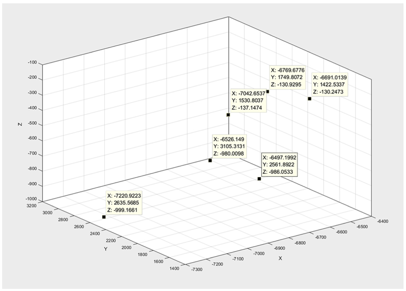
The spherical marker points with the same specifications should be selected, and all of them should be placed on both ends of each reference ruler. The photogrammetry system is used to take several photos of the reference ruler in the measurement space from different orientations and angles, ensuring that each photo contains all or most of the endpoints of the reference rulers to be measured. The coordinates of the end points of three reference rulers were measured by the laser tracker, as shown in Figure 4. From the measured data, It can be calculated that the distance from the ends of three reference rulers to the head of the laser tracker sensor is about 7-8 m, which complies with the experimental conditions. From Figure 4, the specified six coordinates are coordinates of two end points of three reference rulers respectively.
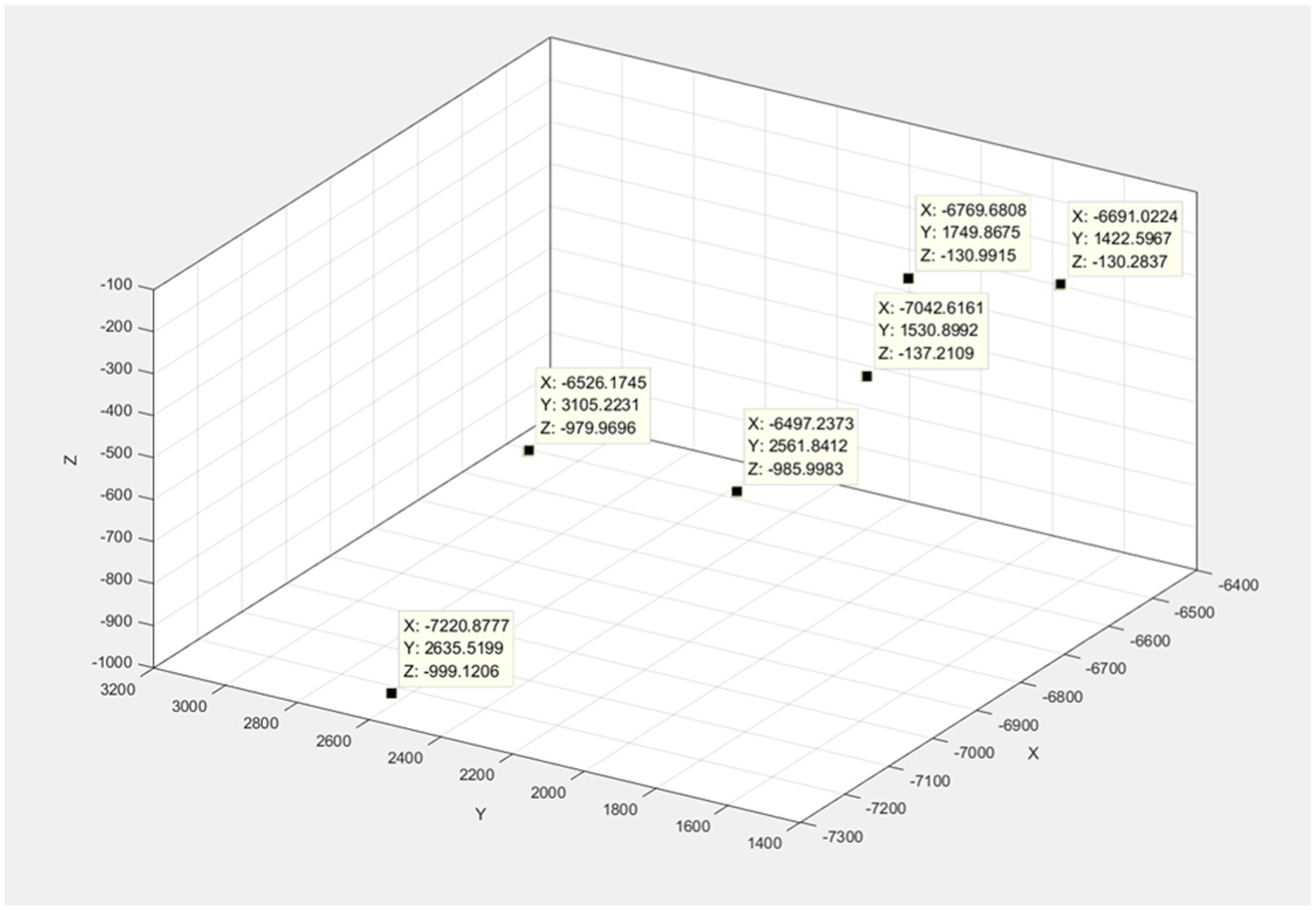
The coordinates of the endpoints of the three reference rulers by the laser tracker.
The endpoints of the three reference rulers were measured using the V-STARS photogrammetry system and the coordinates are shown in Figure 5. It can be derived from the measured data that the distances between the ends of the three reference rulers and the camera of the photogrammetry system are about 2 m, complying with the experimental conditions.
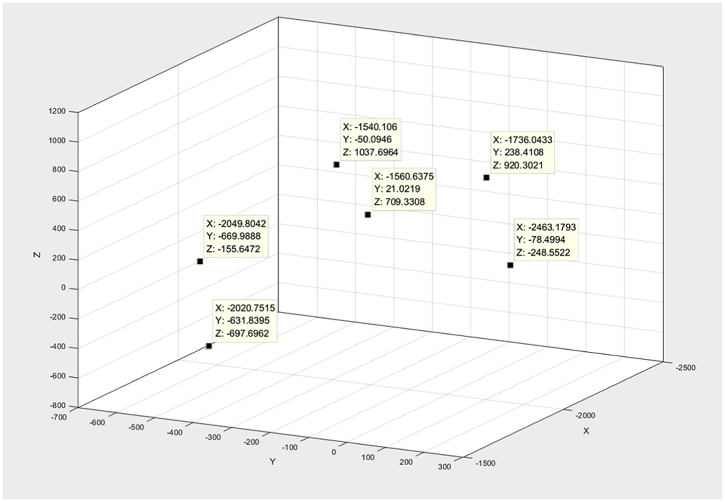
The coordinates of the endpoints of the three reference rulers with the V-STARS photogrammetry system.
Based on the results from the laser tracker and photogrammetry system, the coordinate correction algorithm based on the Rodrigues rotation formula was used to correct the measurement results of laser tracker coordinate system and the corrected results are shown in Figure 6.
The coordinates of the endpoints of three reference rulers with the laser tracker corrected by the photogrammetry system.
Based on the actual length of the reference ruler, the errors between the lengths of the reference ruler and the actual lengths measured by the pre-corrected laser tracker and the errors between the post-corrected measurement lengths and the actual lengths were compared. The same measurement was repeated 10 times, and the averaged value of the measured length errors from three reference rulers was regarded as the error of each measurement and the measurement result is shown in Figure 7.
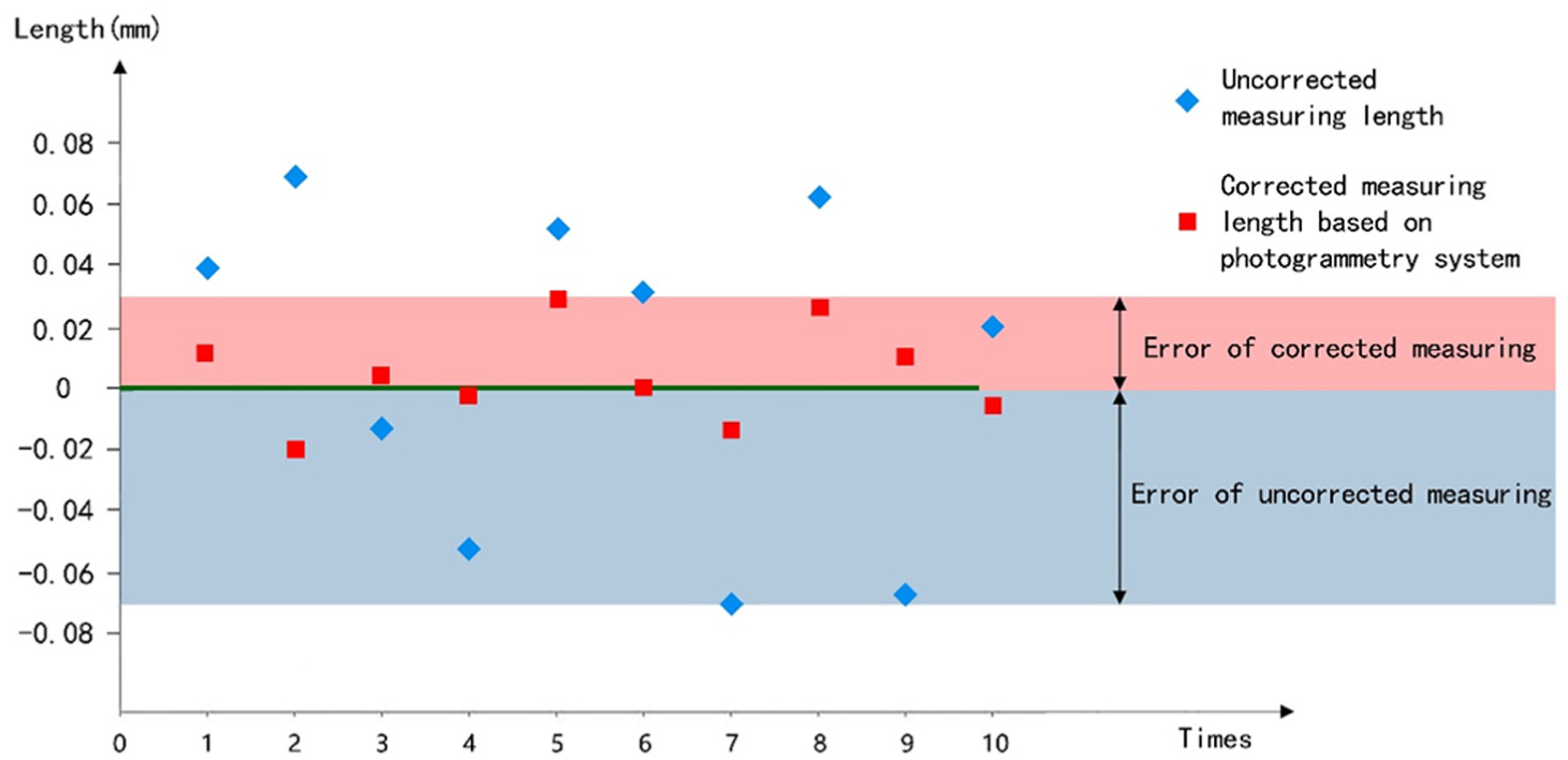
Errors in measuring the reference rulers’ lengths with the laser tracker before and after correction.
Theoretically, when the laser tracker is used to measure the length of over 7 m away from the measured object, the measurement error is approximately 0.06 mm. If the factor of laboratory environment is taken into account, the average length error of the reference ruler measured by the laser tracker is 0.07 mm (Figure 7). After correction by the coordinate correction algorithm based on the Rodrigues rotation formula, the corrected error was 0.03 mm, demonstrating that the coordinate correction algorithm of Rodrigues rotation formula based on photogrammetry can improve the large-scale measurement accuracy of the laser tracker.
Conclusion
To solve the reduction in the measurement accuracy of the large dimensional object with laser tracker when the measurement range increases, a method of using photogrammetry system to improve the large-scale measurement accuracy of the laser tracker was proposed. Based on the portability and high accuracy of the photogrammetry system, the proposed method can achieve higher accuracy when measuring the common points at a closer distance than the laser tracker can do when measuring objects far away from instrument. By the coordinate correction method based on the Rodrigues rotation formula, the data measured by the laser tracker was corrected using photogrammetry results. In addition, three innovations need to be highlighted: (1) we proposed a method of photogrammetry assists measurement of laser tracker, (2) we proposed a coordinate correction method based on Rodrigues’ rotation formula, and (3) the measurement accuracy has been improved when measuring large-scale object using laser tracker. The feasibility of the method was demonstrated by measuring the reference ruler and the accuracy of the method has been evaluated. The experimental results showed that the method proposed in this paper could improve the accuracy of large-scale measurement of laser tracker.
Footnotes
Declaration of conflicting interests
The author(s) declared no potential conflicts of interest with respect to the research, authorship, and/or publication of this article.
Funding
The author(s) received no financial support for the research, authorship, and/or publication of this article.