
Abstract
In this article, a driver model–based direct yaw moment controller, selected as the upper controller, is developed, of which the control target is determined through a reference driver model in accordance with the driver’s intention. The sliding surface is chosen by the difference between the desired yaw rate and the real output yaw rate. Then, the desired yaw moment is calculated by the sliding mode control. In the lower controller, a novel control torque distribution strategy is designed based on the analysis of the tire characteristics. In addition, an admissible control set of the control torques is calculated in real time through an embedded tire model “UniTire.” Finally, a driver-in-the-loop experiment, via the driving simulator, is conducted to verify the proposed direct yaw moment controller.
Introduction
Direct yaw moment control (DYC) representing one type of the electronic stability control (ESC) is used to apply the different longitudinal force between the inner and outer wheels, which can stabilize the vehicle yaw motion and increase the vehicle maneuverability.1,2 There are now three ways to achieve the DYC function: braking, driving, or both. Owing to its simple realization, braking DYC is widely used as the control type; quite the opposite, this mandatory deceleration can distribute the driver’s intention which leads to the accident. On the contrary, the driving DYC can conquer this drawback, 3 but it is implemented by a costly and complex electronic differential.
The in-wheel motor electric vehicle (IEV) has four in-wheel motors, which can independently drive the wheel. The IEV has inherent advantages over traditional vehicles in DYC realization. Without any extraneous components, the DYC system tends to be more flexible and efficient due to the IEV in-wheel motors for which each wheel can be exerted driving and braking forces.
Some control strategies and algorithms of the DYC system development have been presented in the current literature, such as sliding mode control, 4 linear quadratic regulator, 5 fuzzy control,6,7 and model predictive control. 8 Besides, some integrated control including DYC and steering was developed.9,10 There may be still room for improvement as to two points of the current literature. For one thing, the driver’s intention can draw conclusion by the way of measuring the steering wheel angle in the current literature. This method fully depends on the driver’s maneuver behavior; therefore, the driver’s reaction delay and incorrect maneuver directly influence the validity of the control target. For another, the control torques are mainly distributed in proportion and coinstantaneously to the wheels. By this distribution strategy, the potential of the vehicle stabilization cannot be entirely exploited.
This problem has been preliminarily discussed by Chen et al. in previous work. 11 In this article, a more comprehensive analysis and a more objective validation are fulfilled. The contributions of this work can be listed as follows.
First, the control target is determined by a reference driver model, which precisely read the driver’s intention. Therefore, the negative impacts of the driver’s reaction delay and incorrect maneuver are counteracted.
Second, a novel control torque distribution strategy is implemented based on an embedded nonlinear tire model “UniTire.” UniTire also computes the tire adhesive limit in real time, which provides a control boundary aiming to restrict the magnitude of the control vector. Finally, a driver-in-the-loop validation experiment is conducted.
This article is set forth as follows: in “Simulator development” section, the development of a driving simulator is presented. In “Controller design” section, the entire control method is described. The driver-in-the-loop experiment results on the driving simulator are shown in “Driver-in-the-loop experiment results” section. At last, the conclusions are drawn in “Conclusion” section.
Simulator development
A driving simulator was built so as to validate the proposed controller, as shown in Figure 1. The host/target configuration is adopted in the simulator development. In the host PC, the commercial vehicle dynamics software CarSim®12 and the system-design platform LabVIEWTM13 are applied to set up the software environment. In the target PC, the LabVIEW Real-Time Module provides the real-time operating system. The driver’s maneuver command is transmitted to the vehicle dynamics model through the NI PCI-6229 data acquisition board.

Driving simulator configuration.
A passenger car, with the main parameters listed in Table 1, is modeled in CarSim for the simulator. The validation plots of the developed vehicle model are presented in Figure 2. A double lane change (DLC) maneuver is selected, with the vehicle velocity of 80 km/h. The validation results show (comes out) that the CarSim model closely matches the experimental data; therefore, the driving simulator is further used to conduct a driver-in-the-loop experiment. (It is apparent that both the experiment and the CarSim have the same steering wheel angle diagram. Although there do exist a little bit deviation in yaw rate, roll angle, and the lateral acceleration diagrams, the experiment has similar outlines in general, compared to the CarSim, which is within the acceptable range and can be used to conduct a driver-in-the-loop experiment.)
Parameters of the passenger car.
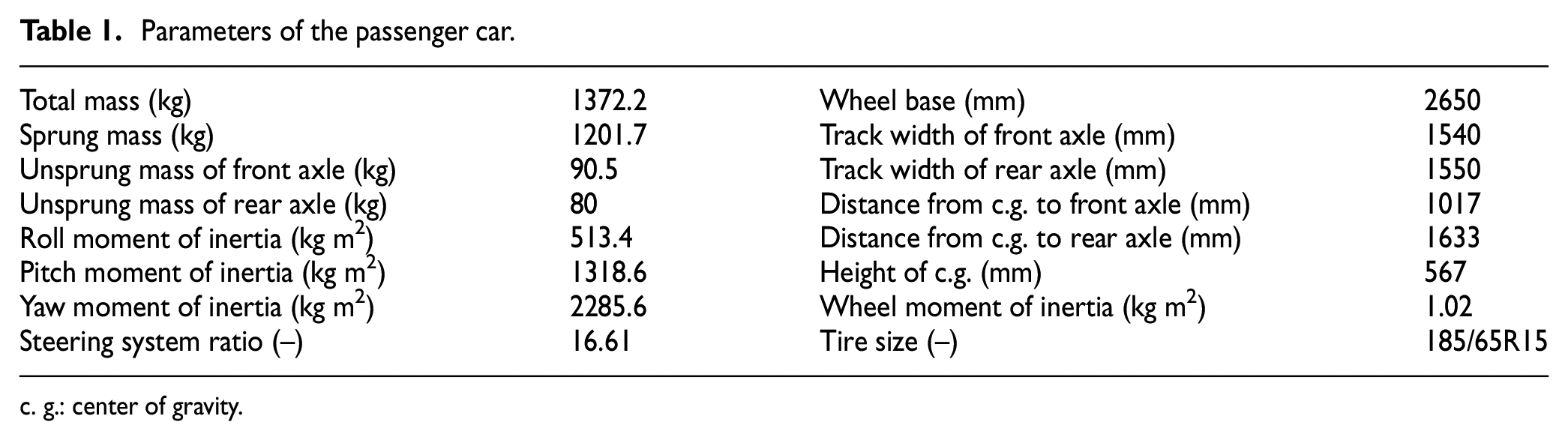
c. g.: center of gravity.

CarSim model validation: (a) steering wheel angle, (b) yaw rate, (c) roll angle, and (d) lateral acceleration.
Controller design
Vehicle dynamics model
A 7 DOF reference vehicle model is developed for the controller design, including longitudinal motion, lateral motion, yaw motion, and rotational motion of the four wheels, which are shown in Figure 3.

7 DOF vehicle model.
The equations of the vehicle motion are expressed as


The four wheels’ rotational dynamics are


Among which the first subscript of
In order to describe the vehicle characteristics more accurately, a semi-physical nonlinear tire model “UniTire,” by Guo and colleagues,14,15 is adopted for the controller design in this article.
The slip ratios of the longitudinal and the lateral in UniTire are defined as


where
The relationships of the normalized slip ratio, the lateral, and the longitudinal are expressed as


where
The normalized resultant force has an exponential equation, expressed as

Furthermore, we can get the longitudinal force and the lateral force by following equation

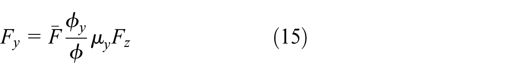
where
The tire force comparisons of the passenger car between the UniTire output and the experiment data are presented in Figure 4. The relationship between longitudinal force
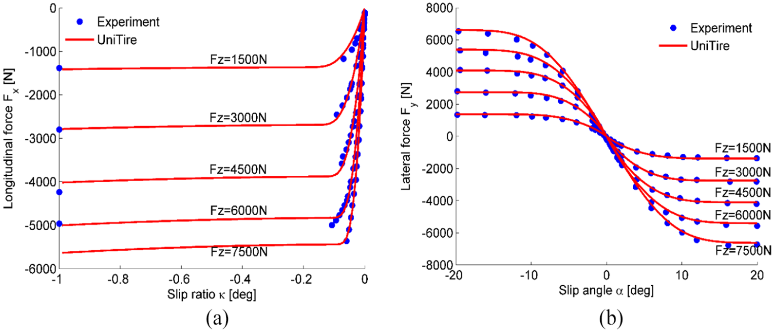
UniTire tire model: (a) longitudinal force with slip ratio and (b) lateral force with slip angle.
Referred to the tire model, the following expressions can represent the relationship between the longitudinal tire force and lateral tire force


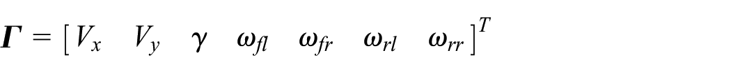
Thus, equations (1) to (7) can be compactly rewritten as

where the vehicle state vector

Outline of proposed controller design
A control target plays a key role in a control system. In a DYC controller, the control target is generally related to the driver’s intention. Therefore, precisely understanding the driver’s intention plays a crucial role in the DYC controller development. Since the driver model is established on the human driver and can, considerably, respond to the human driver’s behavior, the human driver’s intention can be read, which is of great advantage.
A preview driver model in a driver/vehicle system is illustrated in Figure 5
16
: P(s) is the driver’s preview strategy; H(s) is the driver’s control transfer function, in which C(s) is the driver’s regulation and calculation block and M(s) is the maneuver transfer function, which mainly represents the driver’s delay; B(s) is the feedback block; G(s) is the vehicle response; f is the current road information; fa is the road information ahead;

Block diagram of driver/vehicle system.
According to the driver model, the driver’s intention can be directly reflected by the desired steering wheel angle
where
In fact, it seems impossible that
Unfortunately,
A hierarchical control architecture is utilized in this article 1 as illustrated in Figure 6. In the upper controller, the desired yaw moment is determined by the reference driver model according to the road information. In the lower controller, the actuator inputs are calculated according to the desired yaw moment. Moreover, a control boundary is computed in real time through an embedded tire model “UniTire.”

Structure of control system.
Upper controller
Figure 7 is a single point block diagram of the optimal preview acceleration driver model, 16 and the expression of the optimal lateral acceleration can be represented by

with the lateral error

where

Single point optimal preview acceleration driver model.
According to the driver model theory by Guo and Fancher,
17
the term

where
The desired steering wheel angle
Furthermore,

where
Figure 8 illustrates the relationships of

Connections of steering wheel gain, preview time, and velocity: (a)
The human driver’s steering wheel angle and the controller prediction are compared on a certain path in Figure 9. The human driver’s steering wheel angle is measured through the developed driving simulator. It shows that the proposed method can precisely predict the driver’s maneuver. Moreover, the predictive steering wheel angle is slightly ahead of the driver’s actual maneuver in the time domain. This advantage will further help the proposed system act earlier and timelier.

Comparison of driver behavior and controller prediction.
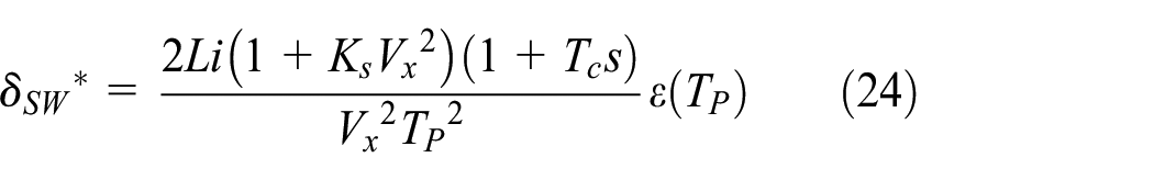
Thus, the control target, desired yaw rate

An approximate upper limit of the yaw rate can be written as
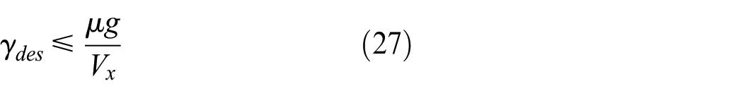
This upper boundary of the control target is to guarantee the desired yaw rate realization. Furthermore, the precise control boundary is realized through a tire model in the lower controller.
In order to get the vehicle yaw rate to track the control target more rapidly and accurately, sliding model control is employed to deal with this control problem.
Let the sliding surface be

Differentiating equation (28) and combining equation (18) yields

with

where
Therefore, the most ideal value of the desired yaw moment approximation

Here, we adopt the continuous relaxed condition to avoid the shudder, and the desired yaw moment is expressed by 18

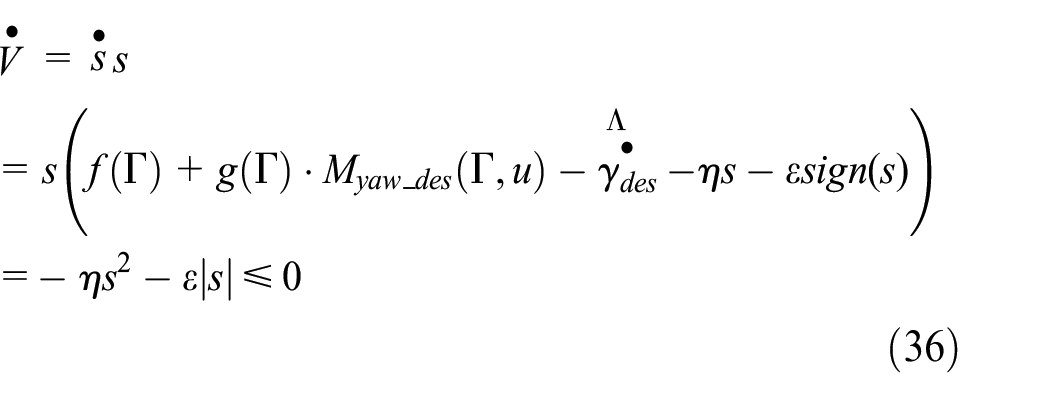
Here, we consider the Lyapunov function as


From equations (33) and (34), the system is asymptotically stable.
Furthermore, the effect of the parameter uncertainty can be avoided by adding a switch gain to the control system; therefore, the differentiation of the sliding surface and the Lyapunov function can be rewritten as

Some vehicle states, including slip angle, tire forces, and friction coefficient, required by the control law, can be obtained indirectly. Hence, there comes some methods to estimate the variables, such as state observer, smart tire technology, and so on. However, in this article, these detailed methods would not be expounded.
Lower controller
Figure 10 is one of the illustrations of the typical tire characteristic under the circumstance of the tire linear region. It shows that if the tire longitudinal force is increased from 0 to
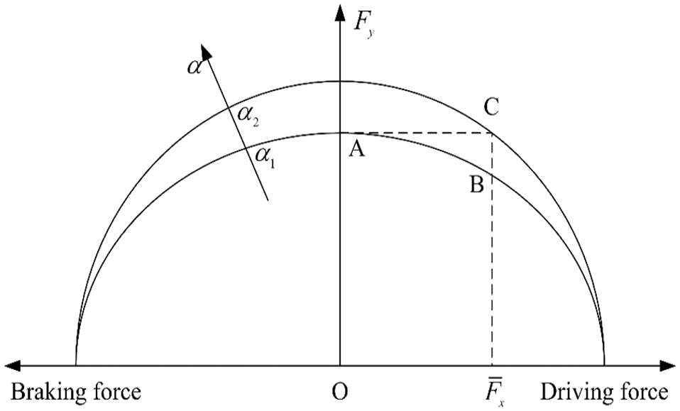
Tire longitudinal force influence on lateral force.
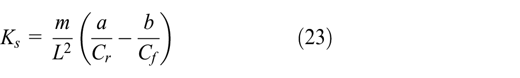
Equation (23) can be rewritten as

That is to say, the vehicle steady cornering characteristic is influenced by the tire longitudinal forces. The vehicle is more inclined to be understeer when the longitudinal forces are impacted on the front wheels. The vehicle has the intention to oversteer when the longitudinal forces are exerted on the rear wheels. On the basis of this principle, the DYC controller effect can be improved by means of reasonably choosing the control sequence, as shown in Figure 11. In an understeer scenario, the control torques are applied on the rear wheels first; in an oversteer scenario, the control torques are exerted on the front wheels first.
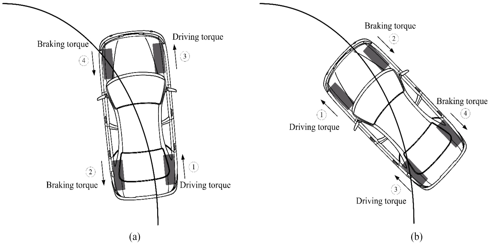
Control torque distribution sequence: (a) understeer scenario and (b) oversteer scenario.
The control torque is supposed to guarantee the resultant force of each tire to be always in the adhesive limit; otherwise, the vehicle stability will even deteriorate. Therefore, another function of the lower controller is to define an admissible control set for the control vector

It is noted that the control boundary of each wheel is individually calculated in the lower controller, which means the entire potential of each tire can be separately exploited. In this case, the stable region of the full vehicle is maximized, and thus, the control effect of the proposed controller can be greatly improved.
The proposed control torque distribution strategy of the lower controller can be summarized and illustrated in Figure 12.
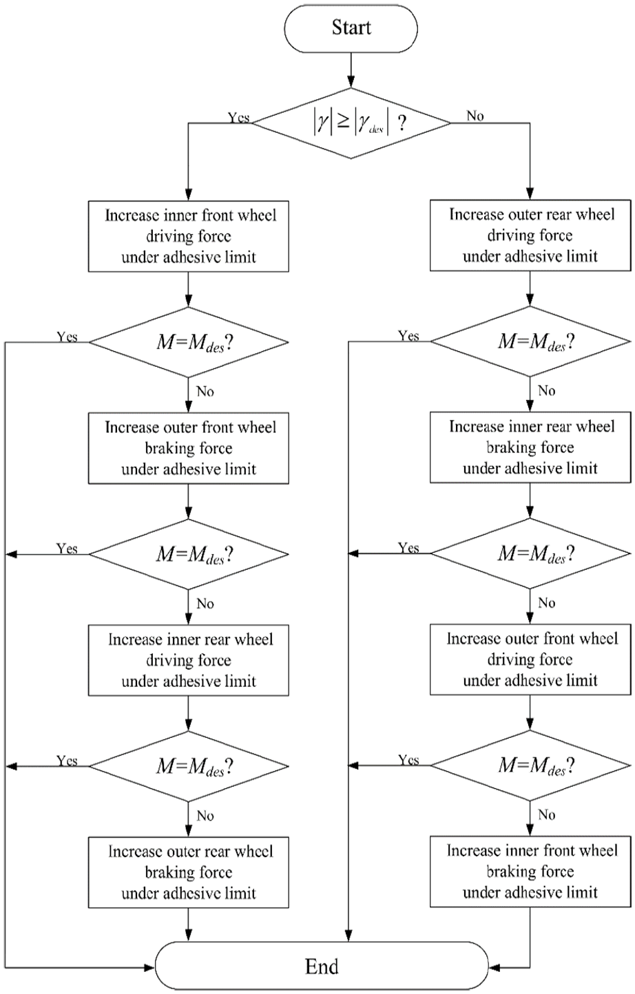
Flow chart of the control torque distribution strategy of lower controller.
By subtracting the equation (33) from equation (30), the difference value can be obtained, which could be rewritten as

In the control method, we consider that the distributions of the right side tire force and the left side tire force are of same value but in different directions, such as when the left side tires exerted driving torque, the right side tires would exert the braking torque. And the direction can be judged by the steering wheel angle and the difference value between the real yaw rate and the desired yaw rate.
Driver-in-the-loop experiment results
Closed loop objective evaluation methods for vehicle handling stability are listed below:
The synthesis of multiple experiments
The overall evaluation of task performance
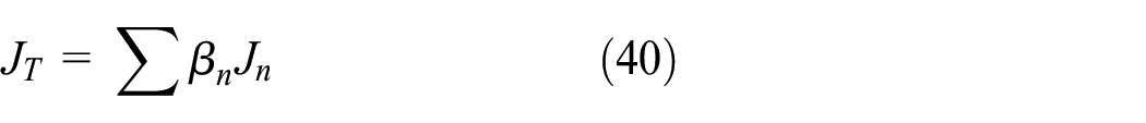
where
The synthesis of multiple vehicle response parameters

where
The synthesis of the entire test section

where
A driver-in-the-loop validation experiment is conducted on the driving simulator. The procedure that the “real” driver maneuvers the “virtual” vehicle can take the human factor into account, and evaluate the proposed DYC system more objectively than a simulation validation. The DLC maneuver is selected for the driver-in-the-loop experiment, with a road friction coefficient of 0.5. For the sake of increasing the persuasiveness of the experiment results, every condition on the simulator is maneuvered three times.
The vehicle without DYC system loses stability at 70 km/h, as shown in Figure 13.

Response of vehicle without control: (a) path, (b) steering wheel angle, (c) yaw rate, and (d) slip angle.
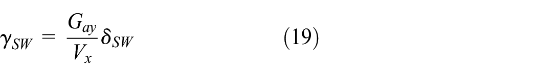
We can ensure that the vehicle without control will lose stability, and the comparison of the vehicle with and without the controller is not given. Instead, in order to illustrate the improved effect of the proposed driver model based DYC system (DMbDYC), it is compared with a steering wheel based DYC controller (SWbDYC), of which the desired yaw rate is expressed by equation (19) or
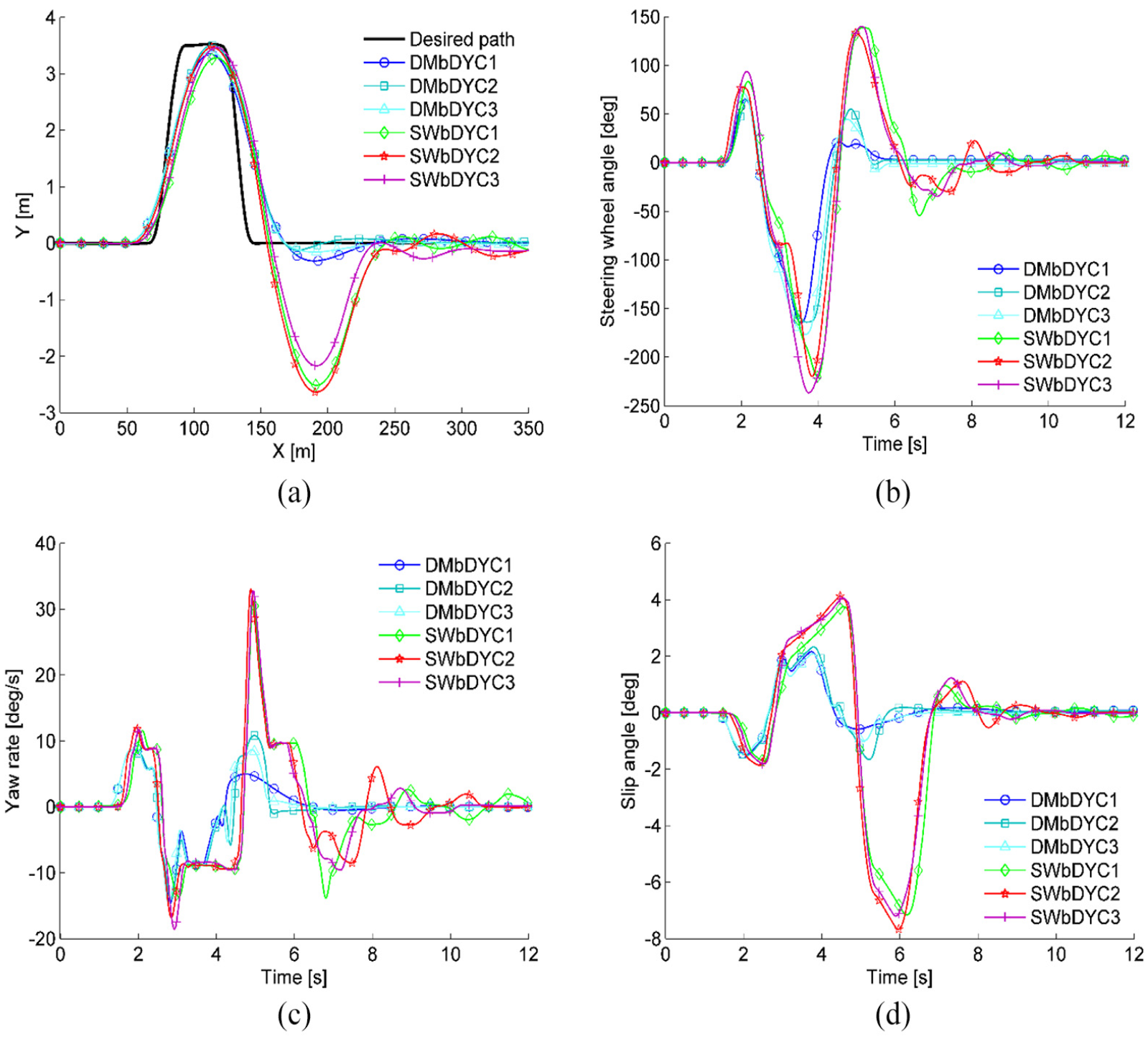
Comparisons of driver model–based and steering wheel–based system: (a) path, (b) steering wheel angle, (c) yaw rate, and (d) slip angle.
During this DLC maneuver, both DMbDYC and SWbDYC stabilize the vehicle to pass the DLC path. However, as shown in Figure 14, the DMbDYC approach is obviously much better than the SWbDYC method.
As shown in Figure 14(a), it is obvious that DMbDYC provides a much better control effect and the vehicle with the help of DMbDYC tracks the DLC path accurately. The vehicle with the SWbDYC system, however, has already slid out of the road.
The impact of the controller on the driver is shown in Figure 14(b): the driver steers the vehicle under the control of SWbDYC with a larger steering wheel angle, which will probably bring the vehicle response out of its linear region. In fact, during the simulator driving, it is very hard to maneuver the vehicle with the SWbDYC system, and the driver becomes panic due to the unfamiliar vehicle response. Under panic, it is possible for a driver to perform an incorrect maneuver, which may lead to a very harmful and dangerous result. In this sense, DMbDYC can reduce the possibility of an accident due to the small steering wheel angle.
Figure 14(c) and (d) provides further evidence of the superiority of the proposed DMbDYC system. The yaw rate of the vehicle with DMbDYC is smooth and the slip angle is small. By comparison, the SWbDYC approach fails to stabilize the vehicle. The yaw rate changes sharply, and the slip angle is relatively large. This means the vehicle is already somewhat unstable.
To sum up, the basic DYC controller is designed by the difference between the 2° model and the vehicle model, which means that the error is not accurately enough due to its simplicity, compared to the SWbDYC and the DMbDYC, which would lead the control target a large fluctuation. Thus, the control system could not follow the desired yaw rate well and get the worse response. And the SWbDYC choose the steering wheel angle to calculate the desired yaw rate, which can present the driver’s intention. The DMbDYC desired the steering wheel angle to calculate the desired yaw rate, which can compensate the driver’s misoperation.
Conclusion
In the proposed controller, the reference driver model is introduced to predict the driver’s intention according to the road information. Since the control target is independent of the driver’s maneuver, the negative impacts by the driver’s reaction delay and incorrect maneuver are reduced and counteracted. The driver-in-the-loop experiment results show that a much better control effect is achieved by the proposed DMbDYC system than the SWbDYC system.
The longitudinal forces exerted in cornering alter the vehicle steady state cornering characteristic. Taking advantage of this point, the distribution strategy of the proposed controller reasonably determines the control sequence to enhance the control effect and to reduce the control power. Besides, the structure of IEV enables the distribution strategy to be more flexible. The IEV is not mandatorily accelerated or decelerated.
The tire model UniTire is embedded in the proposed controller to provide the real-time tire adhesive limit. Since the tire forces can be always guaranteed to be in the friction eclipses, the DYC system can be always ensured to be effective. In addition, the entire potential of each tire is separately exploited, such that the stable region of the full vehicle is maximized. Therefore, the control effect of the proposed controller can be greatly improved.
When we drive on the low friction coefficient road, the tire friction ellipse will shrink significantly. Therefore, any control method can only provide a very limit control effect. If possible, the most practical way to stabilize the vehicle is by decelerating it in advance. Once foreseeing the vehicle unstability caused by driver’s maneuver, the driver model based controller decelerates the vehicle before the maneuver happens. The integrated control with the longitudinal control added into the DYC system will be a subject of future work.
Footnotes
Appendix
Handling Editor: James Baldwin
Declaration of conflicting interests
The author(s) declared no potential conflicts of interest with respect to the research, authorship, and/or publication of this article.
Funding
The author(s) disclosed receipt of the following financial support for the research, authorship, and/or publication of this article: This paper is funded by the National key research and development projects (Grant No. 2018YFB0104804).