
Abstract
Direct yaw-moment control systems have been proven effective in enhancing vehicle stability and handling. The existing direct yaw-moment control designs commonly involve computation of tire side-slip angles, which is susceptible to measurement and estimation errors. The fixed control gain of the conventional sliding mode direct yaw-moment control design cannot adapt to variations and uncertainties in vehicle parameters. As a result, its robustness against parametric variations and uncertainties is limited. To improve the control performance, a novel adaptive sliding mode direct yaw-moment control approach is proposed in this article for electric vehicles with independent motors. The proposed method utilizes a varying control gain to adapt to the variations of front and rear tire side-slip angles. Comparative simulation results show that the proposed scheme outperforms the conventional method with inaccurate tire side-slip angle feedback. With the proposed direct yaw-moment control system on-board, the adverse effects of inaccuracies on tire side-slip angles are suppressed and the vehicle’s robustness against parametric variations and uncertainties is enhanced.
Keywords
Introduction
The swift development of electric vehicles has significantly facilitated the design and implementation of advanced vehicle chassis control systems. One of such systems, benefiting from the configuration of independent driving motors, is direct yaw-moment control (DYC). The simplest way of achieving DYC is through differential braking; however, the inevitable deceleration may disturb the driver and cause accidents. 1 With the distributed motor configuration, DYC achieves independent control over both driving and braking forces, thereby offering a more effective and flexible way for enhancing vehicle stability than four wheel steering 2 and braking (or driving) only DYC. 1
Existing DYC designs normally employ the simple 2-degree-of-freedom bicycle model in the controller design process.3–7 This approach generally requires the knowledge of front and rear tire side-slip angles to obtain the lateral tire forces. To calculate these angles, the following approximations are commonly used8,9


where
Using equations (1) and (2) to compute the tire side-slip angles requires the vehicle side-slip angle
The main shortcoming with the existing DYC solutions is that their control performances are dependent on the estimation accuracy of
To this end, we propose in this article a novel adaptive sliding mode DYC approach for electric vehicles. The major contribution of this work lies in the design of a varying sliding mode control gain which automatically adapts to the changes in tire side-slip angles. By this means, the adverse effects of inaccuracies on
Since sliding mode control technique has been widely employed in recent DYC solutions, 12 a conventional sliding mode control design for DYC is introduced for comparisons in this study. The proposed control approach and the conventional control scheme are applied on a simulated electric vehicle equipped with independently driven rear wheels. The control performances of these two methods are compared, with three types of feedback signals (tire side-slip angles) sent to the two controllers: accurate values, inaccurate values with constant estimation errors, and inaccurate values with convergent estimation errors. The simulation results show that the proposed controller is capable of suppressing the adverse effects of estimation errors and, as a result, presents superior control performance to the conventional approach with inaccurate parameter estimations.
The rest of this article is organized as follows. Section “Problem statement” provides a comprehensive problem statement, including the vehicle models employed in this study, the DYC design problem, and a conventional sliding mode DYC approach. Section “Proposed adaptive sliding mode control” elucidates the detailed design process of the proposed adaptive sliding mode DYC approach. Section “Simulation results” presents the comparative simulation results in different conditions. Section “Conclusions and recommendations” concludes the article and proposes the future work.
Problem statement
In this section, we first present the vehicle models for control system design and simulation validation purposes, respectively. Then, we employ the same notations to introduce the DYC design problem in section “DYC design problem,” as well as a common sliding mode DYC approach in section “Conventional sliding mode control.”
Control model
The typical linear vehicle model, that is, the bicycle model,3–7,13 is commonly used in the design process of various chassis control systems. This planar vehicle model includes 2 degrees of freedom (lateral and yaw motions), and it depicts the basic characteristics of handling dynamics. This model is mathematically expressed as follows


where m denotes the vehicle total mass,
In the bicycle model, the lateral tire force is assumed to be linearly proportional to the tire side-slip angle. Thus, the force


where
During normal driving conditions, the bicycle model is adequate to capture the fundamental characteristics of vehicle dynamics, 14 and its simplicity facilitates the design of chassis control systems. Thus, the bicycle model is employed in this study to devise a direct yaw moment controller.
Simulation model
To produce realistic vehicle responses and verify the control designs, a comprehensive 8-degree-of-freedom simulation model is established. In this model, the vehicle body is composed of two major parts: the sprung rigid body and the unsprung rigid body. To establish the vehicle equations of motion, two Cartesian coordinate systems are attached to the sprung and unsprung rigid bodies. The details of the two-rigid-body configuration and the associated coordinate systems are available in Abe and Manning. 15
Based on the above coordinate systems, one can derive the following 4-degree-of-freedom vehicle equations of motion,12,15,16 governing the vehicle longitudinal, lateral, roll, and yaw motions


where
The external forces and moments


where
The rotational motions of the four wheels provide the other 4 degrees of freedom. Assuming that all four wheels are identical, the equation of motion for the ith wheel is as follows
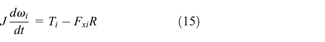
where J represents the mass moment of inertia of each wheel assembly,
The tire forces involved in the preceding equations,

with


where X represents the input variable (wheel slip ratio or tangent of tire side-slip angle);
DYC design problem
With a DYC system on-board, a corrective yaw moment can be generated to tune the dynamics of the electric vehicle, thereby enhancing its stability and handling. Accordingly, the yaw dynamics ( i.e. equations (4) and (6)) in the bicycle model is modified to

where the new term
A typical DYC system is schematically shown in Figure 1. The controller receives measured and estimated vehicle states from sensors and observers, respectively, and calculates the corrective yaw moment
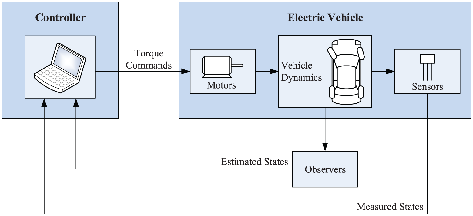
Schematic of a typical DYC system.
In section “Conventional sliding mode control,” we present a common sliding mode DYC approach for illustrative and comparative purposes.
Conventional sliding mode control
In this study, we refer to the commonly used sliding mode DYC approach as the conventional method, and its details are available in previous studies.7,19–21 The design process of this method is generalized in this section.
In the conventional method, the switching function s of the sliding mode controller is normally defined as the error between the actual yaw rate and reference yaw rate

where

where l represents the wheel base. The term K denotes the stability factor and takes the following form

Note that equation (21) is indeed the steady-state yaw rate response derived from the bicycle model,3,9,22,23 which has been widely employed as the reference yaw rate in vehicle stability and handling control.
The control objective of this sliding mode controller is to drive the scalar s to zero and thereafter maintain it at zero. As a result, the actual yaw rate r converges to the reference yaw rate

where
In order for the above sliding condition to be met, in the conventional method, the following

where
With this control input, the derivative of the switching function,

Note that when the switching function s is positive, the sliding condition (i.e. inequality equation (23)) reduces to

Substituting equation (25) in inequality equation (26) yields

On the contrary, when the switching function s is negative, the sliding condition becomes

which leads to

Inequalities in equations (27) and (29) imply that to satisfy the sliding condition, the control gain k must lie in the following range

Since the estimation errors are practically bounded, we might as well assume that

where F represents the upper bound of
In practice, in order to avoid chattering, the “
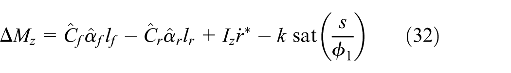
where
Proposed adaptive sliding mode control
Employing a constant control gain k in the control input (e.g. equation (32)) is not desirable for systems with variations and uncertainties in the plant parameters. This fixed control gain k can be insufficient or excessive to produce satisfactory control performance, in the presence of parametric variations and uncertainties.
To overcome the above shortcoming, we propose an adaptive sliding mode controller that employs a varying control gain to adapt to the parametric variations and uncertainties. The learning nature of this adaptive controller improves its control performance as adaptation goes on. As a result, compared to the conventional method, the adaptive control scheme achieves superior overall control performance. The design process of the proposed adaptive sliding mode controller is introduced in the following text.
Based on the control input of the conventional method (equation (24)), the control input of the adaptive controller is proposed as follows

where


Equations (33)–(35) imply that unlike the conventional sliding mode controller, the control gain
The proposed adaptive sliding mode controller must guarantee the stability of the control system. We may employ the following Lyapunov function candidate to evaluate the stability of the system
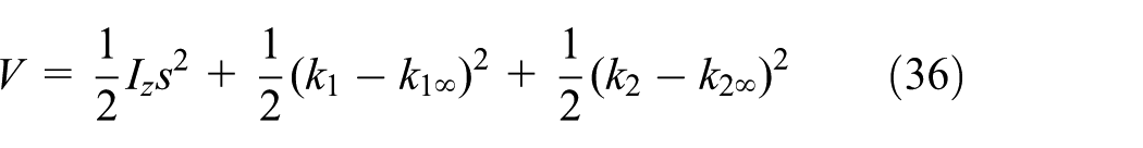
where


Combining equations (33)–(38), the derivative of this Lyapunov function candidate can be derived as follows

Inequality in equation (39) implies that the derivative
Besides, we see from equation (37) that

Similarly, equation (38) leads to
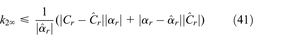
Inequalities in equations (40) and (41) indicate that the boundaries of
Similar to the conventional sliding mode control, the “
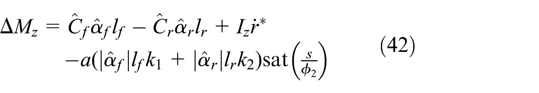
where
In this study, an electric vehicle equipped with independently driven rear wheels is considered, and the structure of the proposed control system for this vehicle is illustrated in Figure 2. The entire controller is composed of two controller units: the sliding mode controller unit and the vehicle velocity controller unit. The former one receives measured parameters from on-board sensors as well as estimated vehicle states from two observers, and then it calculates the control input

where

Schematic of the proposed control system.
Simulation results
In this section, we present the simulation results for both the conventional control scheme and the proposed adaptive control method. The simulation studies comprise three sections: case studies with accurate vehicle states (no estimation errors), case studies with constant vehicle state estimation errors, and case studies with convergent vehicle state estimation errors. In each section, the yaw rate responses and vehicle paths resulting from both control methods are plotted.
The common J-turn maneuver (i.e. a short straight maneuver followed by a constant turning maneuver) is employed in all case studies. The steering input (the steer angle of the front wheels) for this maneuver is shown in Figure 3. As mentioned in section “Conventional sliding mode control,” the steady-state yaw rate response (equation (21)) is employed as the reference yaw rate

Steer angle input for the J-turn maneuver.
The control performances of these two methods are compared and analyzed, with and without parameter estimation errors. The effectiveness of the proposed control design, and its superiority to the conventional method in the presence of parameter estimation errors, will be clearly shown in the following results.
Results without estimation errors
We first present the simulation results under the ideal situation, in which we assume that the vehicle states required by the controllers,

Yaw rate response comparison without parameter estimation errors.

Vehicle path comparison without parameter estimation errors.
Results with constant estimation errors
It is well known that in practice, some vehicle states (e.g.
5% constant estimation errors
First, we feed

Yaw rate response comparison with +5% constant estimation error in

Vehicle path comparison with +5% constant estimation error in

Yaw rate response comparison with +5% constant estimation error in

Vehicle path comparison with +5% constant estimation error in
As shown in the
Due to the existence of the estimation error, the conventional controller is no longer able to generate the desired control command to track the reference yaw rate, which in turn results in significant yaw rate error and vehicle path deviation. However, thanks to the adaptive nature, the proposed controller changes its control gain automatically to compensate for the estimation error. As the adaptation goes on, the actual yaw rate response is driven toward the reference yaw rate. Also, the vehicle path closely follows the ideal one.
10% constant estimation errors
We now enlarge the extent of estimation errors to ±10% and investigate the control performances under severer parameter inaccuracies. Likewise, the results in cases
As shown in the

Yaw rate response comparison with +10% constant estimation error in

Vehicle path comparison with +10% constant estimation error in
In the

Yaw rate response comparison with +10% constant estimation error in

Vehicle path comparison with +10% constant estimation error in
As mentioned previously, the estimation errors deprive the conventional controller of its ability to generate the desired control command and in turn dramatically jeopardizes the control performance. On the contrary, the proposed adaptive sliding mode controller adapts to the changes of vehicle states and guarantees the convergence of yaw rate to its reference value in the presence of state estimation errors.
Results with convergent estimation errors
In control systems where the plant states required by the controllers cannot be directly measured, appropriate observers should be designed to estimate the required states. A properly designed observer should be able to guarantee asymptotic convergence of the estimated states; in other words, the estimation error E should satisfy

where
In this section, we show the simulation results with convergent estimation errors. Namely, the estimated vehicle states

Yaw rate response comparison with convergent estimation error in

Vehicle path comparison with convergent estimation error in

Yaw rate response comparison with convergent estimation error in

Vehicle path comparison with convergent estimation error in
We see in Figures 14 and 15 that when the estimated rear side-slip angle
To clarify the causes that lead to the performance difference between the two control methods, we plot in Figure 18 the control gains of these two controllers with convergent estimation error in

Control gain comparison with convergent estimation error in
It is important to note that the proposed control gain

Besides, the proposed control gain will be reset to zero as soon as the vehicle completes cornering and returns to straight motion (i.e. when
Conclusion and recommendations
The existing distributed-motor-type DYC designs commonly involve the computation of tire side-slip angles, which is susceptible to measurement and estimation errors. In this article, we first introduce the conventional sliding mode control scheme with a fixed control gain and then propose a novel adaptive sliding mode DYC approach that utilizes a varying control gain to adapt to the variations of tire side-slip angles. With the proposed control method, the adverse effects of inaccuracies on tire side-slip angles are suppressed, which in turn enhances the system robustness against parametric variations and uncertainties.
The conventional control scheme and the proposed control method are compared under various simulation conditions. In an ideal situation where the tire side-slip angles are accurately estimated, both methods produce good yaw rate and vehicle path responses. However, in practical situations where the tire side-slip angle information contains estimation errors (different levels of constant errors or convergent errors), the control performance of the conventional control scheme deteriorates significantly. In comparison, the proposed control method maintains consistent control performance with inaccurate tire side-slip angles and outperforms the conventional control scheme in terms of tracking the reference yaw rate and reference vehicle path.
The proposed DYC method can provide a corrective yaw moment to effectively enhance the stability and handling of electric vehicles. The focus of our following research will be on the integration of DYC and other advanced intelligent safety systems, to further enhance the safety and dynamic performance of electric vehicles and pave the way for future autonomous driving.
Footnotes
Handling Editor: Zhixiong Li
Declaration of conflicting interests
The author(s) declared no potential conflicts of interest with respect to the research, authorship, and/or publication of this article.
Funding
The author(s) disclosed receipt of the following financial support for the research, authorship, and/or publication of this article: This work was supported by the National Natural Science Foundation of China (Grant No. 51805055), the National Key Research and Development Project (Grant Nos 2018YFB0106102 and 2018YFB0106104), and the Specialized Research Fund for Chongqing Key Industries Common Key Technology Innovation (Grant No. CSTC2015ZDCY-ZTZX60009).