
Abstract
The four-wheel independent driven electric vehicle (4WID-EV) can easily realize the four-wheel independent drive, which is convenient for the development and design of the direct yaw moment control system (DYC). Based on the theory of ADRC and the sliding mode control, a new type of DYC controller coordinated with the AFS controller using PID method is designed for the 4WID-EV in this paper. The coordinated control work area is divided according to the tire lateral force linear area. An improved particle swarm optimization algorithm which introduces linear decreasing inertia weight and annealing strategy is adopted to obtain the coordination work weight. The effectiveness of the DYC controller is verified by the Simulink simulation. It also shows that the performance is further improved after the coordinated control.
Keywords
Introduction
Ecological deterioration, energy depletion and other issues are increasingly perplexing the survival of human beings, and the vehicles that people rely on for daily travel mainly rely on burning fossil fuels, which undoubtedly aggravates the ecological and energy problems. In addition to the good environmental protection effect, electric vehicles have the advantages of high-energy conversion rate, low noise, recyclable energy and so on.
The Four-wheel independent driven electric vehicle (4WID-EV) can drive each wheel independently by installing a hub motor on four wheels separately. The electric vehicle with this driving form is more compact and has higher transmission efficiency, which will make it an important direction for the development of new energy vehicles in the future. At present, the 4WID-EV has not been mass produced and only appears in the concept vehicle. As a result, the research on the handling stability and safety performance of the 4WID-EV has become one of the current research. 1
In the late 1990s, Toyota Motor Company of Japan began to develop 4WID-EV. Research focused on the key technologies of improving the design of traditional automobile to adapt to the installation of hub motor, including the control of anti-lock brake system (ABS), anti-skid drive system (TCS) and electronic stability control system (ESC) by hub motor. 2
The laboratory led by Professor Yoichi Hori of Tokyo University transformed the traditional vehicle, and developed 4WID-EV “UOT Electric March I” and “UOT Electric March II” successively. Based on the advantages of accurate measurement and control of wheel hub motor and independent drive of four-wheel hub motor, the direct yaw moment control is studied. 3
The PCG group of Tsinghua University led the development of the 4WID-EV Harry, and carried out research on permanent magnet synchronous wheel motor control, electric vehicle braking energy feedback, driving torque distribution, etc. 4
With the popularization of 4WID-EV technology, vehicle stability has been paid more and more attention. During steering, the vehicle is continuously being disturbed by various kinds of interference, which may risk the stability or even lead to traffic accidents. Therefore, it is necessary to control the vehicle and keep the vehicle body running stably. Active front steering (AFS) system can add a front wheel angle to the front wheel of the vehicle by the driver’s turning of the steering wheel, and improves the stability of the vehicle by adjusting the lateral force of the tire. Direct yaw control (DYC) can generate the yaw moment by driving or braking the wheel, so as to produce the desired yaw motion. AFS and DYC are both used for vehicle lateral stability control, and there is likely to be interference and conflict between them, which will weaken the original functions of each system. Therefore the coordinated control of AFS and DYC can give full play to the advantages of both of them.5,6
The working area of vehicle driving can be divided into linear area and nonlinear area. The nonlinear area can be divided into transition area and saturation area. The steering wheel input in the linear area has a simple linear relationship with the vehicle’s yaw rate response. Generally, the driver only has the experience of driving in the linear area. Once the vehicle deviates from the linear area, the driver often makes the wrong operation due to lack of experience, which often leads to traffic accidents. 7 The lateral force characteristics of the tire can also be divided into linear area and nonlinear area (transition area, saturation area). The lateral force saturation of the tire is an important factor that causes the vehicle to deviate from the linear area. 8 AFS, which controls the lateral force of tire, is suitable for the linear area of the tire, not for the nonlinear area, while DYC has no such limitation.
Karbalaei et al. used the fuzzy controller to coordinate AFS and DYC. The fuzzy coordinated controller, which adjusts the weight coefficients of AFS and DYC in real time according to different working conditions, only uses AFS in linear area, only uses DYC in saturated area, and uses AFS and DYC coordinated control in nonlinear area. 9 Behrooz Mashadi designed the sliding mode controller of active steering and direct yaw moment. They use the sliding mode controller of the upper layer to get the total additional yaw moment, and then make AFS work in the linear area of the tire. If the maximum wheel angle of AFS’s output still cannot meet the additional yaw moment, DYC comes to work. 10
In China, Zhao Wei of Chang’an University designed the fuzzy controller of AFS and DYC respectively, and designed the coordinated controller to adjust the weight coefficient between the two fuzzy controllers. 11 Tian Jie et al. Of Jiangsu University designed the threshold value according to the yaw rate deviation when turning. When the threshold value is exceeded, the coordinated controller is adopted. When the threshold value is not exceeded, only the AFS control is used to improve the response characteristics of the vehicle. 12 Du Song of Jilin University uses the phase plane analysis method to divide the independent working area of active steering and active braking and the area where they work together. The particle swarm optimization algorithm is used to solve the corresponding parameters, and the distribution coefficient of active steering and active braking under the joint action is obtained. 13
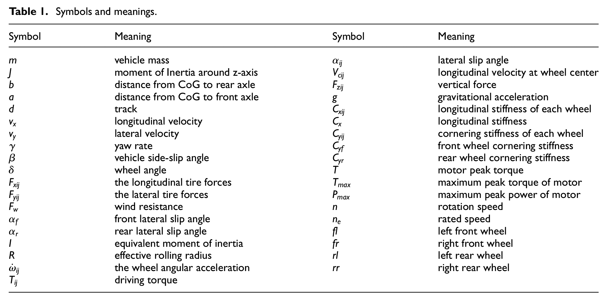
According to the characteristics of AFS and DYC, this paper designs the AFS controller based on the PID method and the DYC controller based on the sliding mode active disturbance rejection method, and then divides the linear area and nonlinear area following up the tire lateral force curve so as to develop a coordinated control strategy: the AFS control is only used in linear area, the DYC control is only used in saturation area, and the weight coordinated control is used in transition area. An improved particle swarm optimization algorithm is adopted to obtain the coordination weight. The simulation proves the effectiveness of this control algorithm. The symbols and meanings used in this paper are as Table 1.
Symbols and meanings.
Vehicle Model
Vehicle model
(1) The three degrees of freedom of body movement
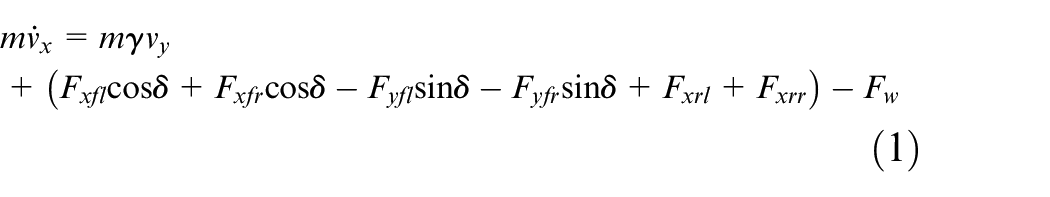
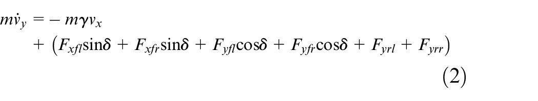
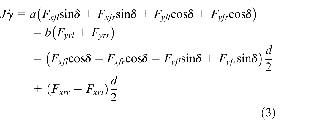
Ignore the influence of suspension, so as to ignore the car’s pitch, roll and other movements. The rolling resistance of the wheel and the aligning torque is ignored, too. 14 It is considered that the center of mass is a constant, and the steering angle of left front wheel and right front wheel is the same. Then the dynamic equations considering three directions are obtained.
Vehicle longitudinal (along x-axis) dynamic model:
Vehicle lateral (along Y-axis) dynamic model:
Vehicle yaw (around Z-axis) dynamic model:
The vehicle side-slip angle at the point is defined by:
(2) Four degrees of freedom for four wheels to rotate


Auxiliary calculation model
(1) Lateral slip angle 15
When the wheel is rolling, the actual direction of the wheel speed is not parallel to the wheel plane, but presents a certain angle
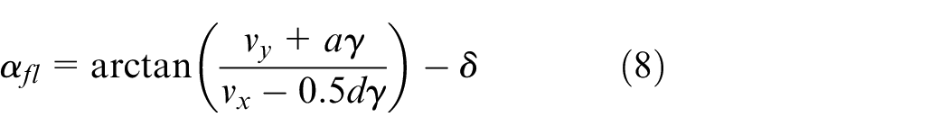
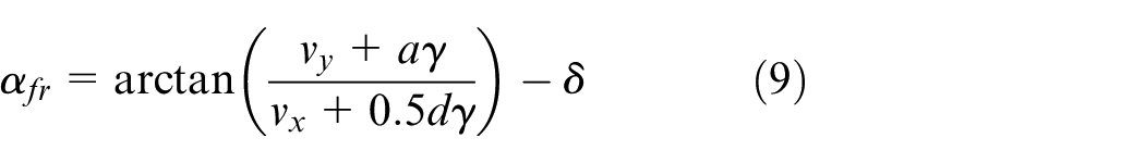
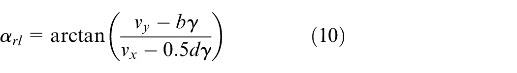
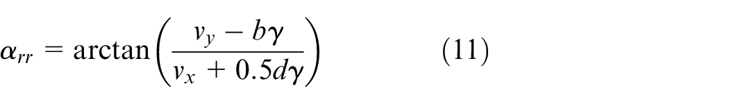
In some cases, the following simplified treatment is often done. It is assumed that the lateral-angles of the two front wheels and the two rear wheels are equal. As a result, the lateral slip angles of front wheel
In this paper, in addition to the vehicle model used in the actual experiment using the (8) to (11) model, the other cases are using the simplified lateral slip angle model.
(2) Longitudinal velocity at wheel center 16


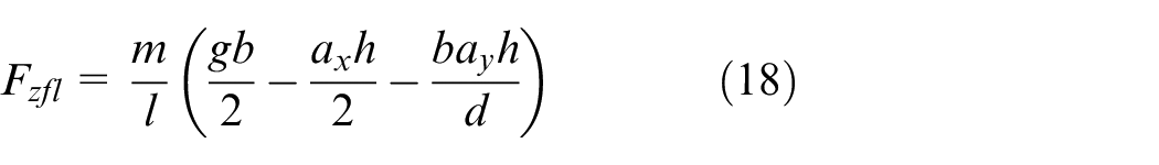
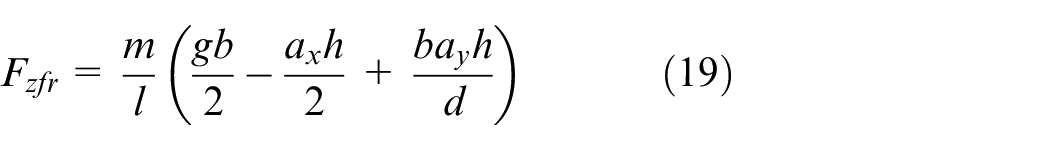
(3) Vertical force 16
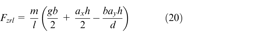
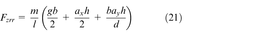
The vertical force of the four tires varies with the vehicle steering, acceleration and other conditions. The neglect of roll and pitch can be determined by the following four formulas:
Tire model
The Dugoff model 17 has the advantages of small amount of calculation, fast calculation speed, high accuracy and no need of experimental data fitting, which can basically reflect the tire force characteristics. Therefore, this paper selects the Dugoff mode as the tire model of the vehicle.
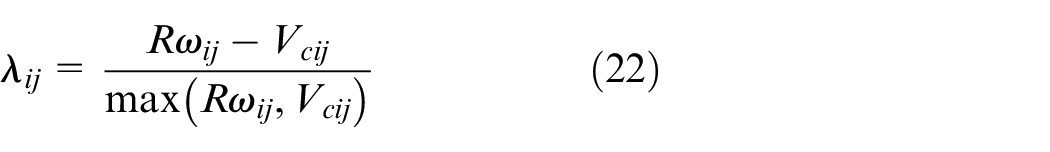
(1) Longitudinal slip
The longitudinal slip of the vehicle can be expressed as the following formula, while in case of driving condition:
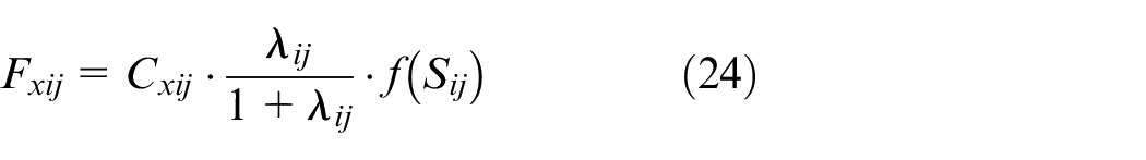
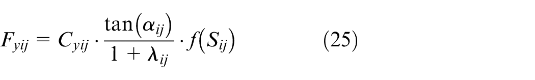
(2) Lateral slip

(3) Under combined conditions
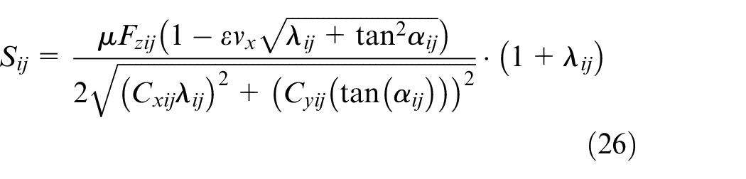
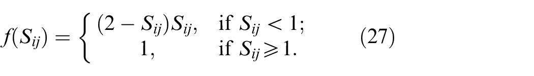
In this paper, we can think that there are
Wheel Hub Motor
According to the research focus of this paper and for the sake of simplicity, this paper does not make a detailed modeling of the inner part of the hub motor and only considers the external characteristics of the motor. The PI controller is used to control the longitudinal speed of the vehicle. The motor demand torque is calculated according to the target speed, and then it is output by the four-wheel hub motors.
The external characteristic curve of the motor reflects the limit of rated speed to motor peak torque, which can be expressed as the following formula: 16
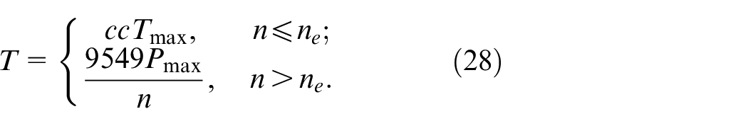
According to the method of article,16–18 the motor parameters are matched.
Nominal model
The dynamic model of the linear two degrees of freedom illustrated in Figure 1 is widely used in the vehicle control. It can better describe the driver’s intention in the linear area of the vehicle, and is often used to represent the ideal steering characteristics of the vehicle.19,20
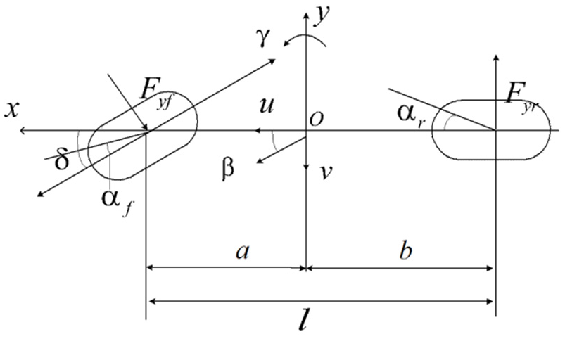
The dynamic model of the linear two degrees of freedom.
The model is as follows:


Since additional yaw moment can be applied by the DYC system, an additional item M is added after formula (30), which becomes:

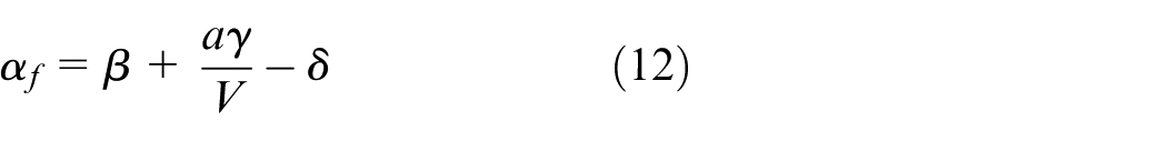
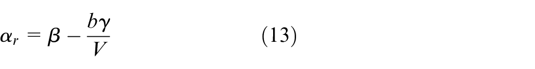
Considering that when the car is in the linear area, the tire is also in the linear area, and the lateral force of the tire is directly proportional to the lateral slip angle of the tire, the simplified formula (12) and (13) of the lateral slip angle are as follows:
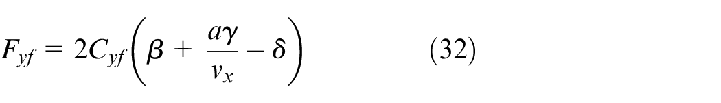
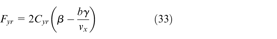
Substituting equations (32) and (33) into equations (29) and (31) into the form of state space:

where
When the vehicle is under the uniform driving condition,
where
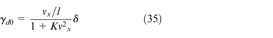
The nominal yaw rate is taken as:
In this paper, the nominal vehicle side-slip angle is set to 0, which is conducive to the track keeping and helps to prevent the tire force saturation.
The controller design
The AFS controller design
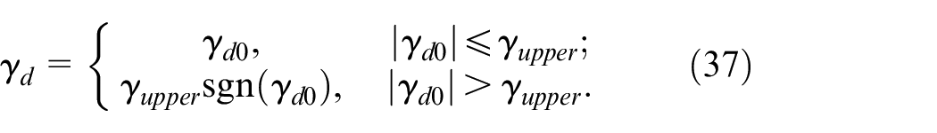
The PID control is to generate the control quantity in the form of linear combination after the error between the value of controlled variable and the given value is passed through the proportion element(P), integral element(I) and differentiation element(D). It has the advantages of simple operation and strong applicability. 22 The principle is shown in Figure 2.
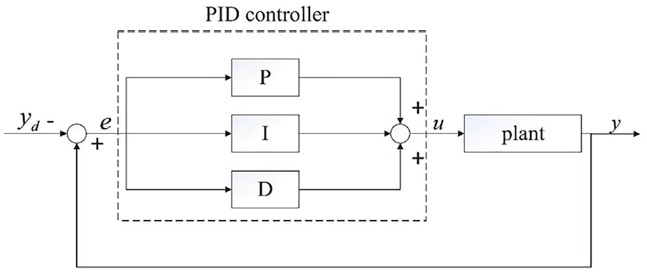
Typical PID controller.
The value of given signal is:
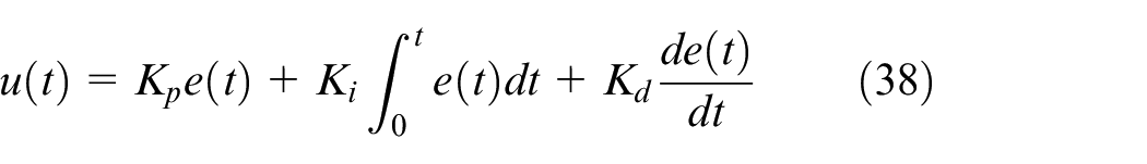
Where
The PID control is usually based on the linear model of the linear control method, and the AFS system uses the front wheel lateral force, in the linear area of the car and therefore has a good control effect. Therefore, this paper does not develop a new control algorithm for AFS and adopts the simple and stable PID control to ensure a certain control accuracy. Considering that the D unit may amplify the noise of the system and have a serious adverse effect on the control effect, the PID control in this paper is actually a PI control. Because the vehicle side-slip angle is very small in the linear region, the stability of the vehicle is mainly determined by the yaw rate,
23
therefore this paper only aims at the AFS system designed to control the yaw rate. The control quantity of the controller is: the error between the yaw rate and its nominal value
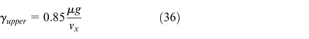
Considering the physical limitation, the amplitude of
The DYC controller design
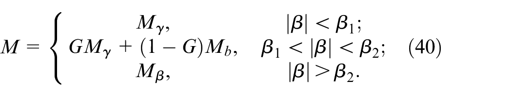
There is a coupling relationship between the yaw rate and the vehicle side-slip angle. In order to solve the coupling between them, the following strategies are selected: when the vehicle side-slip angle is small, only the yaw rate is controlled; when the vehicle side-slip angle increases to a certain extent, the yaw rate and the vehicle side-slip angle are jointly controlled by the weighting coefficient. When the vehicle side-slip angle is too large, only the vehicle side-slip angle is controlled. 23
Decision layer of yaw moment
The typical ADRC is designed as a structure composed of four parts:24–28 fast tracking differentiator (TD), nonlinear state error feedback (NLSEF) extended state observer (ESO), and disturbance estimation compensation. The structure diagram is as Figure 3.
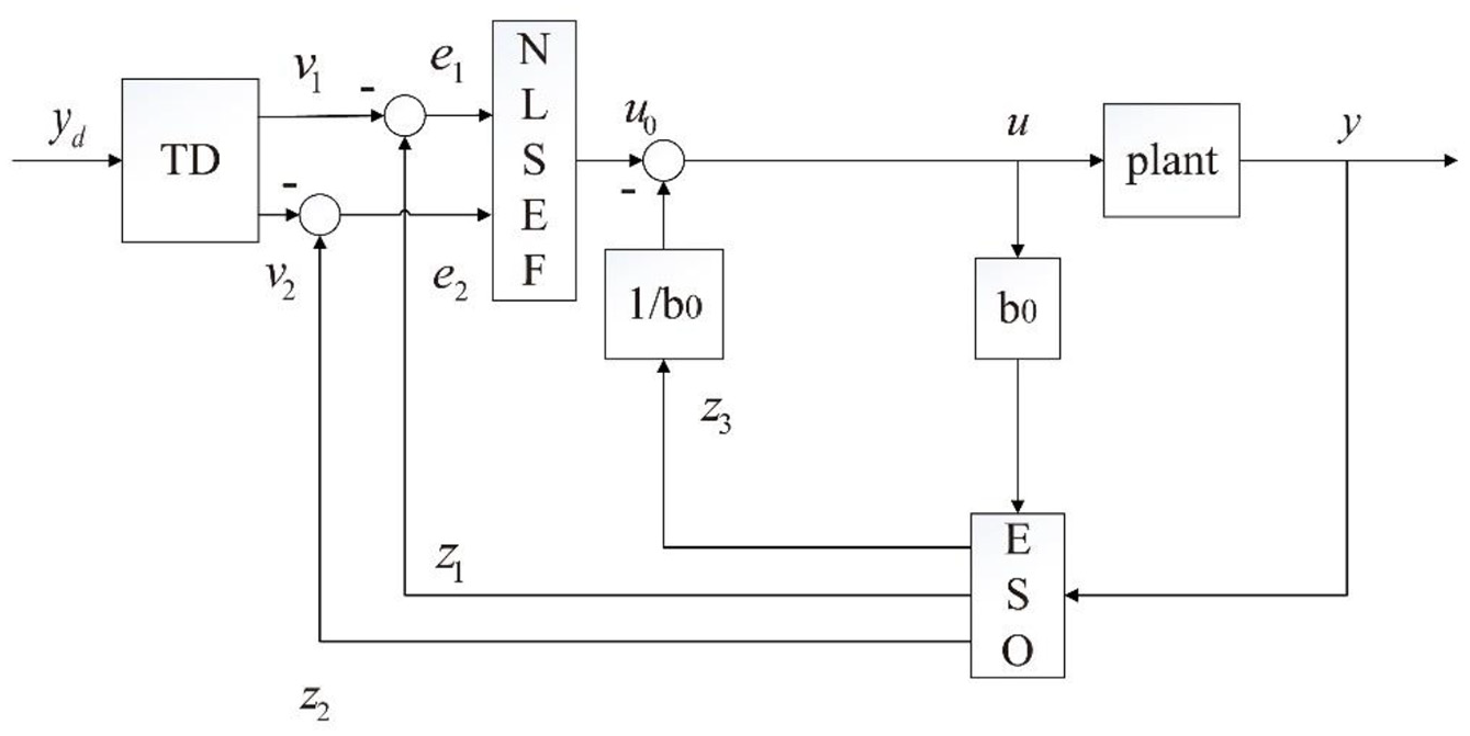
Structure diagram of classical ADRC.
Based on the arrangement of the transition process, TD overcomes the limitation that the output variable can’t track the jump to quantitative because of the inertia. At the same time, it gives a proper method to extract the differential signal to avoid the noise amplification in the differential process. NLSEF gives the nonlinear combination control quantity through the nonlinear function, which expands the application scope of the traditional PID proportional integral differential linear combination, and avoids the closed-loop sluggish, oscillation, integral saturation and other problems caused by integral feedback. ESO and disturbance estimation compensation can accurately estimate all kinds of unknown disturbances of the system. It is not necessary to measure the disturbance or know the disturbance model in advance, so it is convenient to realize simple error feedback control of the system.
In traditional ADRC, the sign function is often used in TD, which is not smooth or continuous. It is easy to produce jitter and slow convergence in the control process. In addition, the control function used is complex and requires too many parameters to be adjusted, which is not easy to adjust. 29 In ESO, fal function is often used, which also has the problem of too many parameters to be set, and there is a boundary inflection point, which causes fluctuation near the boundary inflection point and reduces the dynamic performance. 30
In view of the above shortcomings, TD is designed based on hyperbolic tangent function in article, 29 and ESO is designed by inverse hyperbolic sine function instead of fal function in article. 29 The paper 31 also extends the form of nonlinear combined control strategy by combining sliding mode control. Combined with the above results, this paper designs an active disturbance rejection controller combined with the sliding mode control to design the DYC system, control the yaw rate and the vehicle side-slip angle, and improve the vehicle yaw stability. The formula (34) can be converted into two second-order systems in the following forms, which are respectively used to design the yaw rate controller and the vehicle side-slip angle controller.32,33
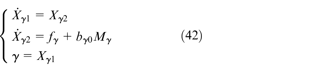
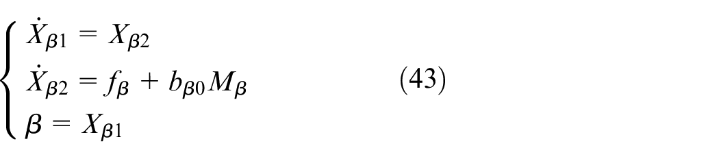
In the formula,

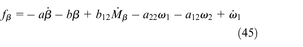
It includes modeling, unmodeled dynamic disturbance and external disturbance, where
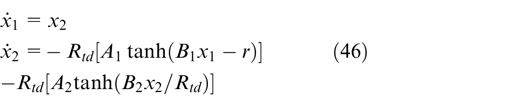
(1) TD based on the hyperbolic tangent function 29
(2) ESO based on the inverse hyperbolic sine function 30
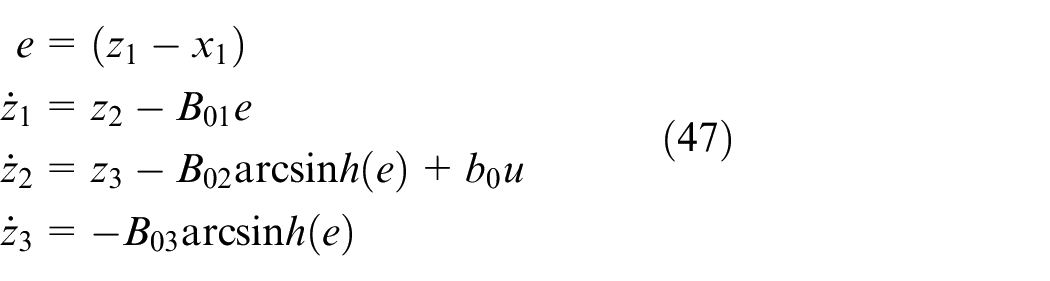
In the formula,
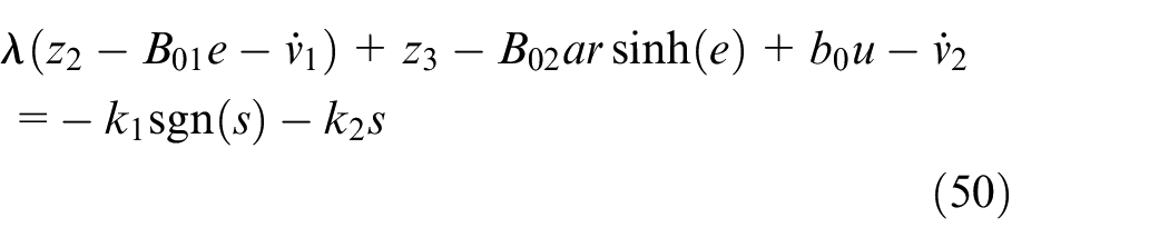
(3) NLSEF combined with the sliding mode control
Take sliding surface as

Substitute

Substitute the observer formula (47), that
Lyapunov function
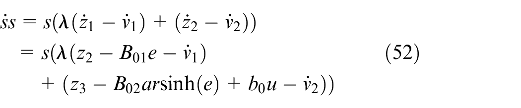
Substitute
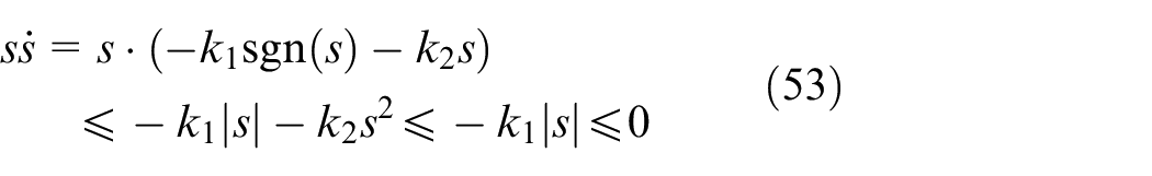
So that the system is stable.
(4) Disturbance compensation
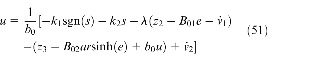
Considering that the direct output control quantity of the sliding mode control module is

Thus, the direct output control value of the sliding mode control module is obtained as:
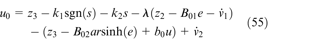
In order to avoid high frequency vibration caused by sign function, inverse hyperbolic sine function is used instead. The output control quantity
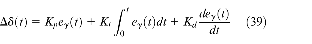
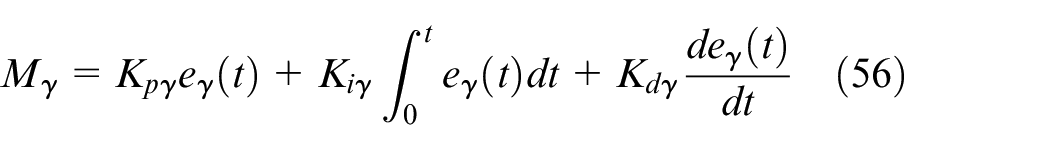
In this paper, the DYC controller based on the PID design is chosen as the comparison, which proves the superiority of the DYC controller designed in this paper. Using the strategy of (40)-(41), the yaw rate and the vehicle side-slip angle are controlled respectively, and the control quantity is output according to the weight. When the yaw rate is controlled, the input of the controller is: the yaw rate deviates from its nominal value
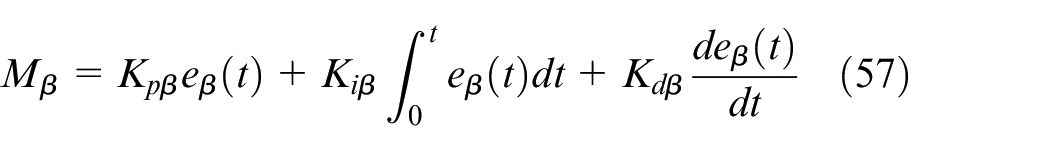
When the vehicle side-slip angle is controlled, the input of the controller is: the vehicle side-slip angle deviates from its nominal value (
Driving force distribution layer
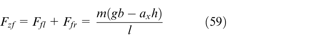
In order to simplify calculation and ensure real-time performance, the method of axle load ratio distribution 34 is adopted:
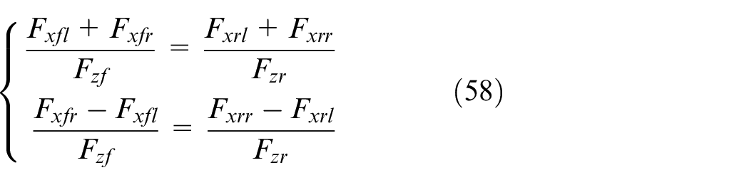
From the vertical load formula (18)-(21), the front and rear axle vertical forces are respectively:

According to formula (58) and considering that the angular acceleration of formula (4)-(7) is small, it is considered that there is
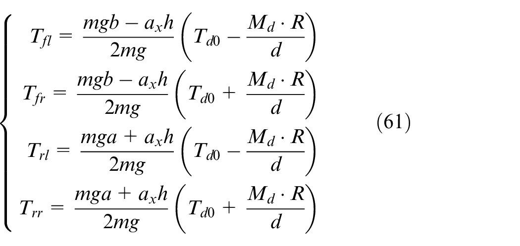
Where

Coordinate strategy
The paper 35 puts forward a method to divide the working area of AFS and DYC system according to the linear area of the curve of tire lateral force changing with the tire lateral slip angle, which will be used in this paper as well.
According to the vertical force formula (18) to (21), when the vehicle is turning, the vertical force is transferred to the outer side wheel, the vertical force of the four wheels is not equal, and each tire may be in different working areas. As a result, the influence of the vertical load must be considered.
In this paper, the critical values of the tire lateral slip angle in linear-transition area and transition-saturation area are measured on the road with the vehicle speed of 120km/h, with front wheel cornering stiffness of –40,000 n/rad, rear wheel cornering stiffness of –68,000 n/rad, vertical force range of 1000 n to 70,000 n, and the adhesion coefficient of 0.4.
The measurement method is to take the tire lateral slip angle corresponding to the point where the slope of the tire lateral force curve starts to decline with the change of tire lateral slip angle as the critical value of the linear-transition area. According to the reference, 35 the tire lateral slip angle corresponds to the point where the slope drops to 30% as the critical value of the transition-saturation area.
Then, the curves of the critical value of the lateral slip angle with the vertical force in the linear-transition area and the transition-saturation area were fitted, respectively. The fitting results are as Figures 4 to 7.
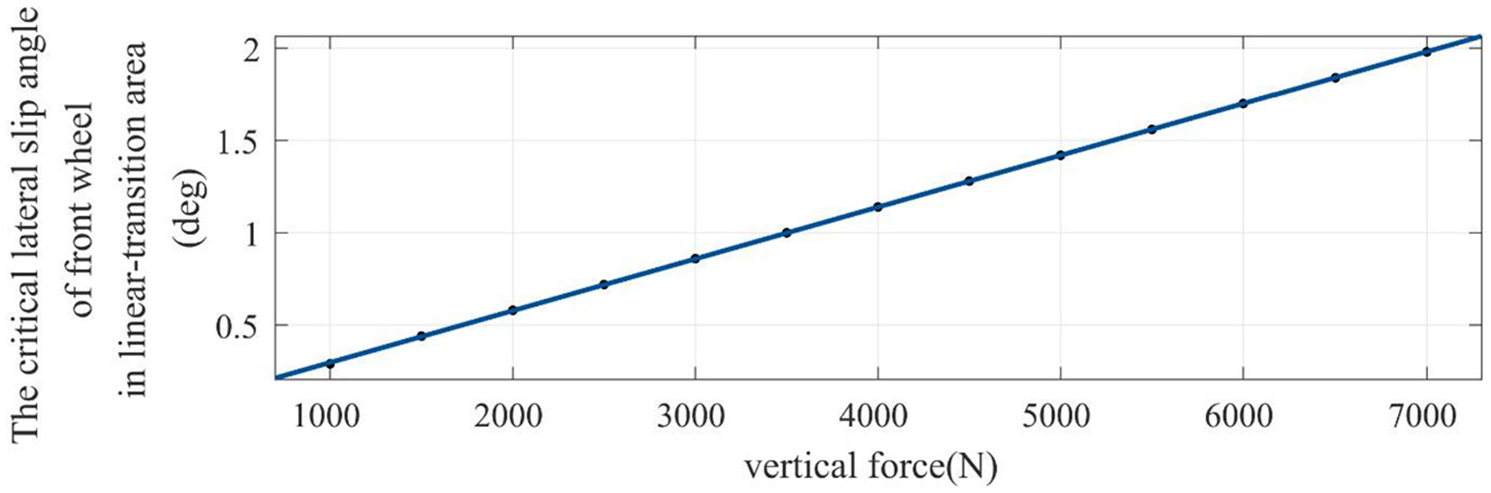
The critical lateral slip angle of front wheel in linear-transition area.

The critical lateral slip angle of front wheel in transition-saturation area.
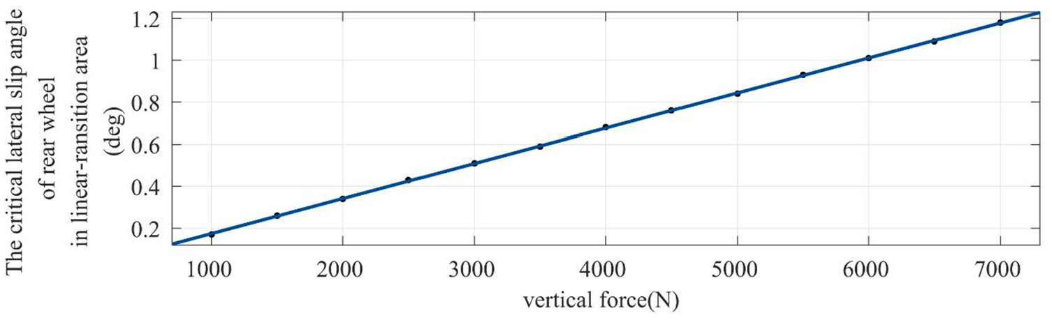
The critical lateral slip angle of rear wheel in linear-transition area.
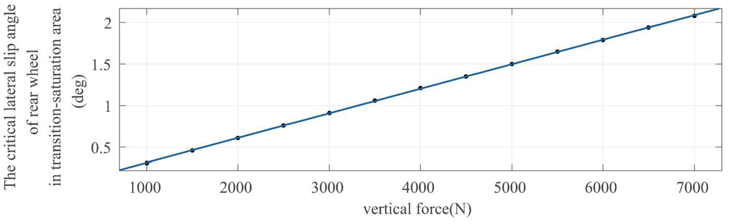
The critical lateral slip angle of rear wheel in transition-saturation area.
Based on the above results, the critical lateral slip angle (subscript 1 stands for the critical value of linear-transition area and 2 stands for critical value of transition-saturation area) obtained from the fitting curve under the corresponding adhesion and vertical force is compared with the front wheel lateral slip angle and rear wheel lateral slip angle calculated according to formula (12) to (13), if
System parameters in the simulation.
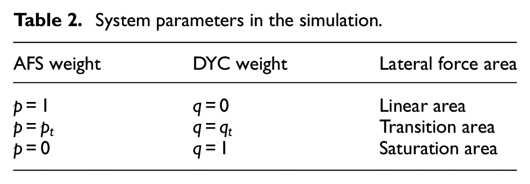
where
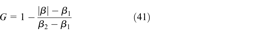
For transition area weights
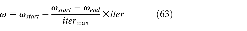
Where,
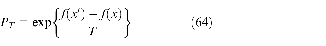
Among them,

where
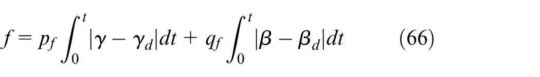
where
The control flow of the improved particle swarm optimization algorithm is illustrated in Figure 8.
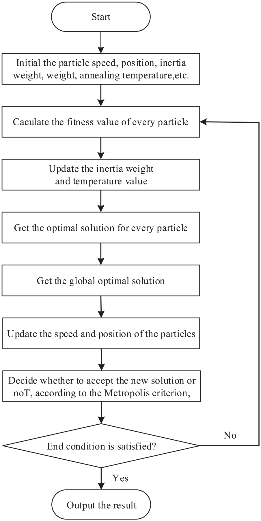
The control flow of the improved particle swarm optimization algorithm.
Simulation
In this chapter, the low adhesion road with a coefficient of adhesion of 0.4 is selected to simulate under the front wheel angle with an amplitude of 3°. The DYC control based on PID, as a contrast test with the sliding mode ADRC controller designed in this paper, does not participate in the coordinated control experiment. In order to simulate the measurement noise in real environment and verify that the designed controller is not sensitive to noise interference, the input variables (including the yaw rate, the vehicle side-slip angle, the front wheel angle) of the controller designed in this paper are all added with white noise with an angle amplitude of about 0.05. Then DLC experimental conditions will be used for this test.
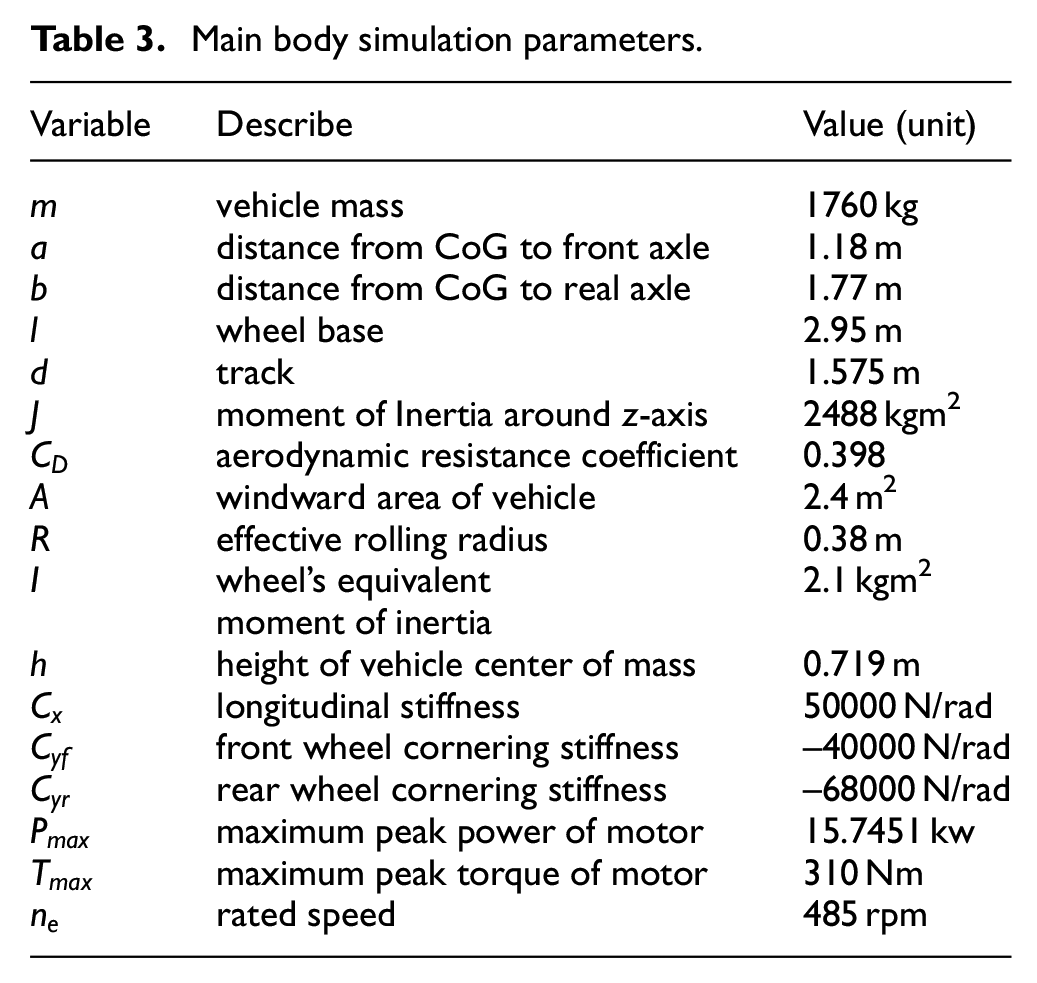
The simulation parameters are as Table 3.
Main body simulation parameters.
The simulation input curve is as Figure 9 and the simulation results are as Figures 10 and 11.
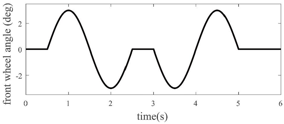
Input angle of front wheel in DLC experiment.
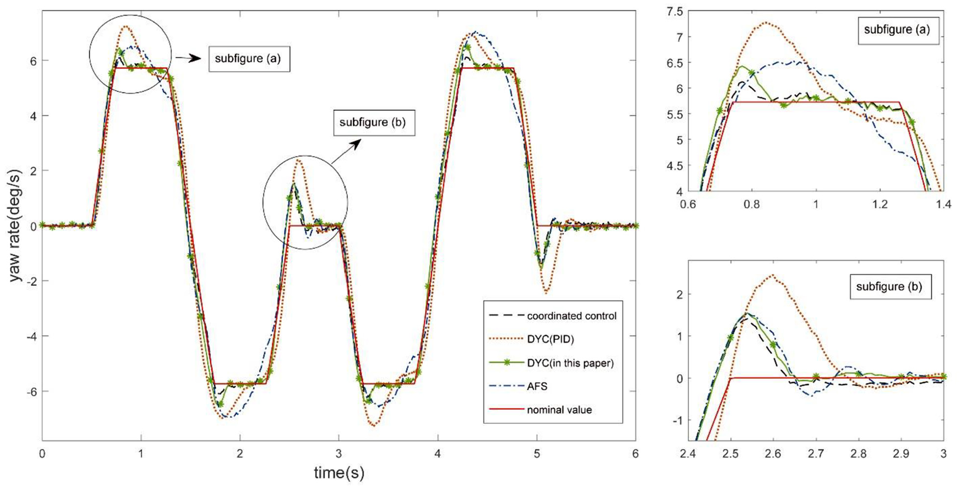
Yaw rate in DLC experiment.
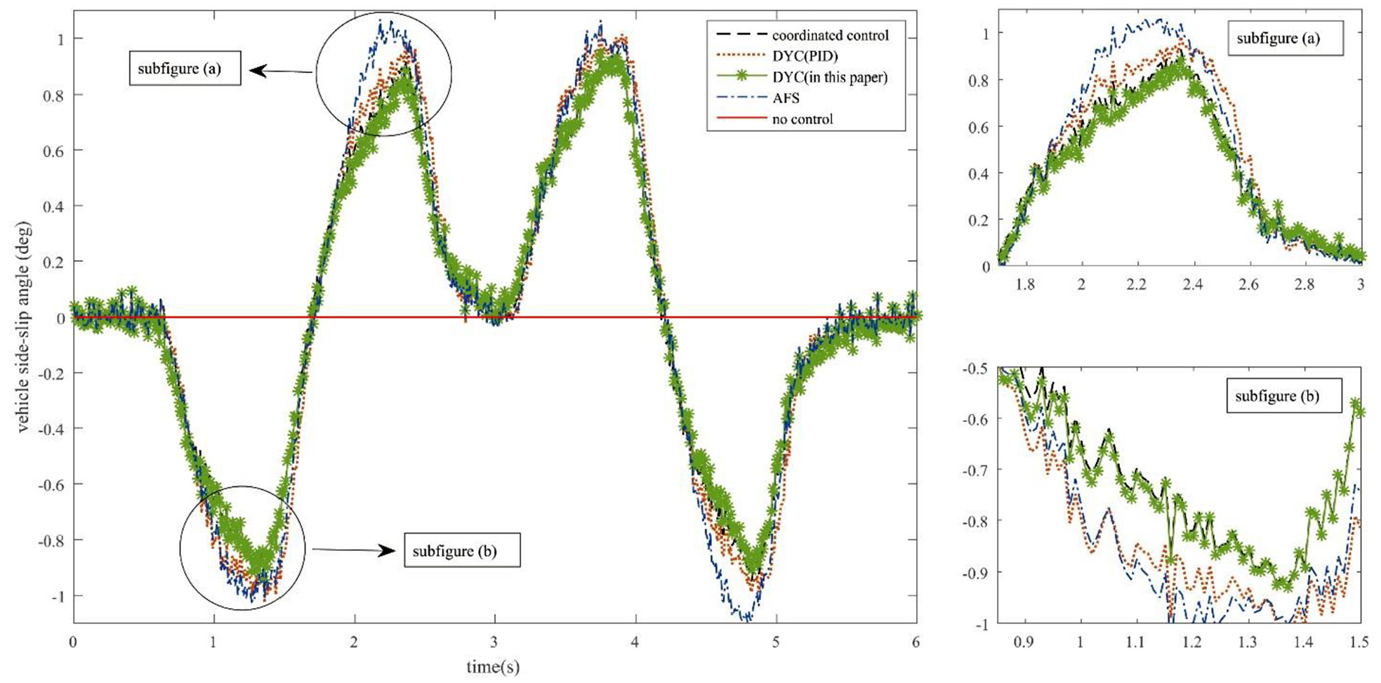
Vehicle side-slip angle in DLC experiment.
It can be seen from Figures 10 and 11 that the uncontrolled vehicle yaw rate error and vehicle side-slip angle error are both very large and with poor stability. After control, the error of the yaw rate and the vehicle side-slip angle are obviously reduced. The control effect of the yaw rate of the DYC controller based on PID is obviously worse than that of the DYC controller proposed in this paper, and it is worse than that of the AFS controller in some time periods. The effect of the vehicle side-slip angle is only slightly better than that of the AFS controller, which is less than that of the DYC controller designed in this paper. The control effect of the yaw rate and vehicle side-slip angle of the DYC controller designed in this paper is better than that of AFS. After the coordinated control, the error of the vehicle side-slip angle is not significantly reduced, but the error of yaw rate is further improved.
Conclusion
The AFS controller based on PID and the DYC controller based on sliding mode active disturbance rejection designed in this paper can make the vehicle yaw rate and the vehicle side-slip angle better track the nominal value, which effectively improve the vehicle yaw stability. Meanwhile, the DYC controller designed in this paper is better than the DYC controller based on PID. After the coordinated control, both the tracking effect and stability are further improved. As the sensors to measure the lateral slip angle are very expensive, the algorithm to estimate the lateral slip angle rapidly and precisely will be considered in the future work.
Footnotes
Declaration of conflicting interests
The author(s) declared no potential conflicts of interest with respect to the research, authorship, and/or publication of this article.
Funding
The author(s) received no financial support for the research, authorship, and/or publication of this article.