
Abstract
It is a common phenomenon in the movement of the quadruped mammals accompanied with head swings. Inspired by this, this article attempts to add head motion to the bounding gait of a quadruped robot. According to the theoretical analysis, there are two main functions of the head. First, the head can realize the active control of the center of mass position of the robot, which is of great significance to the stable motion of the robot. Second, the swing of the head plays a role in regulating the pitch angle of the torso and improves the coordination and stability of the motion. A simplified quadruped robot model with a head and spine joint is established and analyzed theoretically. The regularity of head movement in periodic bounding gait is summarized. Through simulation and experiment, we confirm the two roles of the head in the bounding gait of a quadruped robot.
Introduction
The quadruped robot has always been a hotspot in the fields of robotics. A quadruped robot with a spine motion is an important aspect of the research. A large number of studies have shown that the spine motion can improve the speed and energy efficiency 1 of quadruped robots. However, in the actual situation, spinal joints increase the degree of freedom of the system and make the system unstable, at the same time. Therefore, in order to solve the contradiction between the flexibility and stability of the quadruped robots, many experts and scholars have performed a lot of research.
Many studies have shown that spinal motion plays a vital role in the high-speed movement of mammals.2,3 So many engineers have studied the possibility of spinal joints used for quadruped robots. The BDI cheetah, designed by Boston Dynamics (BDI), had an articulated back that flexed back and forth on each step. With that design, it was capable of running up to 28.3 mile/h with off-board power while constrained in two-dimensions (2D) by a boom. Some similar quadruped robots with spinal joints can be seen in the design of MIT Cheetah, 4 Bobcat-robot, 5 and Lynx-robot. 6 Throughout these studies, it has been found that the addition of spinal joints increases the forward speed of the quadruped robot and reduces energy consumption. Unfortunately, there are no mature quadruped robots with spine joints that can move outside the laboratory.
In addition to the above studies of spinal motion, many researchers have found that the other body parts in the quadruped, such as the tail and head, are also critical to the movement of animals. R Briggs et al. added a tail-like swing mechanism to MIT Cheetah. Through analysis and experiment, they showed the effectiveness of a tail in body reorientation and disturbance rejection. 7 SW Heim et al. added an active tail to the quadruped robot Cheetah-Cub. They proved that an active tail can both greatly improve forward velocity and reduce body pitch per stride. 8 In addition, the tail plays an important role in free-falling robots 9 and bionic lizards running on the water. 10 In most studies, the tail is made of a rigid rod, but there are exceptions. WS Rone and Pinhas-Ben 11 designed a flexible tail with a gear mechanism. Compared to the impact of a tail on the performance of the quadruped robots, the research on the head is relatively less. XL Zhang et al. 12 designed a quadruped robot with a 1-degree-of-freedom (DOF) pitch head and a 1-DOF roll tail, and proposed that the movement of the head and tail is coupled with the movement of the limbs. S Suzuki et al. 13 suggested that head movement is crucial for the reproduction of the gait transition to high-speed gaits in quadrupeds. Other studies on the movement of the head are mainly for the purpose of visual stability, since the autonomous quadruped robots have to mount cameras on the head.14,15
The goal of this article is to verify that the addition of head movement can effectively improve the motion performance of a quadruped robot with a spine joint and to explore the mechanism of head motion. We will begin with a brief introduction of the inspiration from animal movement in nature and preliminarily summarize the law of head movement. Then, we build a bounding model of the quadruped robot with head appendage and spine joint. We use the simplified model to study the mechanism of head action. We will summarize the movement law of the head in a periodic bounding gait and establish a criterion to measure the stability of bounding motion. After that, the effect of head movement on bounding gait of a quadruped robot will be verified by simulation and experiment.
Bio-inspiration
In the design of quadruped robots, many design inspirations can be obtained by observing the quadruped animals. Bionics is to extract design principles from nature, not just the imitation of animal structures.
Figure 1(a) shows the galloping gait of a greyhound. It can be seen that the head has a distinct up and down swinging motion. In Figure 1(b), in the Belgian Malinois’ bounding gait, the head undergoes a process of swinging from top to bottom and from bottom to top. The angle of the head relative to the trunk changes over time. When the birds walk on the ground, their head will sway back and forth. In the long jump competition, in order to get a longer jump distance, the athletes will swing their arms back and forth. The action of head movement in quadrupeds is similar to that of arm swing in humans. The movement of the head plays a role in regulating the movement of the quadrupeds.
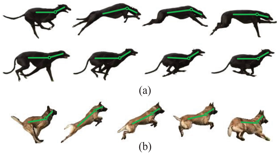
Head movement in exercise of dogs: (a) greyhound galloping gait and (b) Belgian Malinois’ bounding gait.
In Figure 1, we can see that the spinal motion is coordinated with the head movement. When the spine contracts, the head swings upward, and as the spine stretches, the head swings downward.
Quadruped bounding model with an active spine
Model description
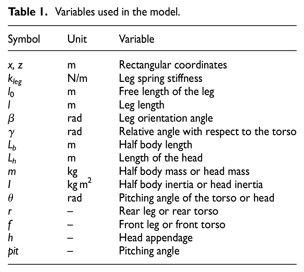
A simplified model of a quadruped robot is shown in Figure 2. The construction of the model refers to the design of Cao and Poulakakis, 16 which is a planar robot model. The torso consists of two rigid segments that are symmetrical with respect to the spine joint. The rotation in the sagittal plane can be achieved by an active spinal joint. The front and rear legs are simplified into massless spring legs. A head that can be actively rotated is attached to the front torso. Adding a head appendage to the model is the biggest difference between the research reported in this article and previous research. A detailed description of variables and indexes in Figure 2 is shown in Table 1.

Planar simplified model of the quadruped robot with an active spine and head appendage.
Variables used in the model.
The position of the center of mass (COM) of the front torso is at point (xf, zf). The position of the COM of the front rear torso is at point (xr, zr). The position of the COM of the head is at point (xh, zh). The COM of the whole torso is at point B, (xb, zb). And we get

Define the pitch angle of the torso as θpit, and, through the geometric relationship shown in Figure 1, we can get

where θf is the front torso pitch angle and θr is the rear torso pitch angle.
The relative rotation angle of the spinal joint is recorded as θs

Asymmetric body mass distribution
The foot end is subjected to the reaction force

Force diagrams of the quadruped model in the rear leg supporting phase: (a) without and (b) with a head appendage. Here, point B is the COM of the trunk, H is the COM of the head, and W is the COM of the overall quadruped model.
Define

From the previous analysis, we can get

where τ is the driving torque of the hip joint.
The torso is simplified to the mass point B, the head is simplified to the mass point H, and the O is the hinge point of the head and torso. In Figure 3(b),
Therefore, the coordinates of the overall COM at this time can be calculated as
where

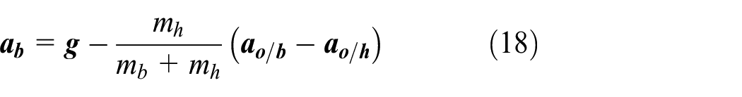
Due to the addition of the head, the offset of the COM in the horizontal and vertical directions is set to ax and az, respectively. From equations (1) and (7), we can get ax and az as follows

where me is the relative mass of the head given by

In one stable motion,
According to the above analysis, we can change the position of the COM in space by changing the rotation angle of the head. The increase or decrease in the vertical direction is uncertain, but due to the addition of the head, the COM position tends to move forward in the horizontal direction. In the absence of a head, the quadruped robot model is symmetrical with respect to the spinal joint. After the head appendage is added, the body mass distribution of the model is asymmetrical.
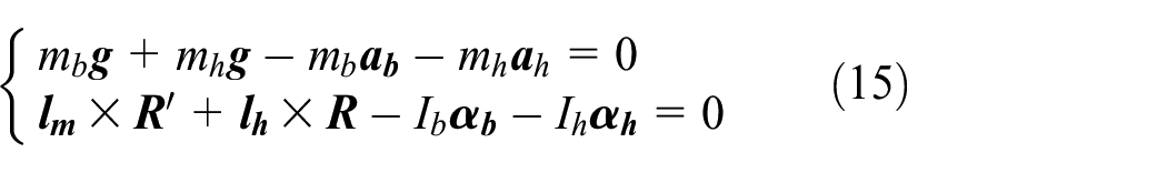
In the rear leg supporting phase, the following equation is always valid


where
We specify that the moment
Head swing and torso pitch motion
A simplified model of the quadruped robot in the flight phase that does not subject to ground forces is shown in Figure 4. The torso is simplified to the centroid point B, the head is simplified to the centroid point H, and the head and torso are hinged at point O. At the joint between the head and the torso, the head is subjected to the force

Simplified model of head and trunk movement: (a) the model combination state, and (b) the model decomposition state.
Applying Newton’s second law and Euler’s second law for body B yields

Likewise, for the head H

Equations (13) and (14) sum and rearrange to give
Expressing

where
Substituting equation (16) into equation (15) yields

Solving equation (17), we obtain
Substituting equation (18) into equation (13) yields an expression for the reaction force

where
Let db be the distance from force


Substituting equations (20) and (21) into equation (15), we get

Rearranging equation (22), we get

Integrating equation (23), we yield a statement of angular momentum conservation

where H is an arbitrary constant.
Equation (24) can be further abbreviated as

where
It can be seen from equation (25) that the angular momentum of the system is conserved at a certain moment in the flight phase. If the initial angular velocity of the system is zero, by integrating equation (25) and rearranging it, we get

It can be seen from equation (26) that the rotation of the head during movement can drive the torso to rotate in the opposite direction.
Stable cycle bounding gait
Periodic motion design
Based on the observation of the quadrupeds, we can summarize some characteristics of the bounding gait. The bounding gait of the quadruped robots with a head and an active spine in one cycle is shown in Figure 5. This study is about bounding under high-speed motion, so each time at most one leg is in the supporting phase, regardless of the situation that the front and rear legs are in the supporting phase at the same time.
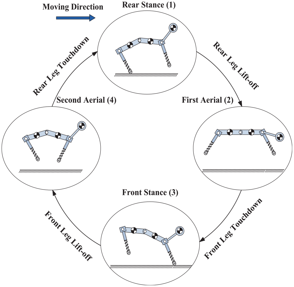
Phase sequences of bounding gait for stability analysis.
In Figure 5, the quadrupedal bounding model has four phases, the rear stance phase (numbered 1), in which phase the spine is compressed and the head swings upward. In the process of transition from phase (1) to the first aerial phase (2), the spine stretches, the rear leg lifts off the ground, and the head swings downward and gradually enters phase (2). During the transition from phase (2) to the front stance phase (3), the spine contracts, the head swings upward, and the front leg touches the ground and gradually enters phase (3). During the transition from phase (3) to the second aerial phase (4), the front leg swings backwards, gradually leaving the ground, and then enters (4), at which time the spine’s contraction angle reaches the maximum. After that the rear leg touches the ground and enters (1) the rear leg stance phase to complete a cycle of bounding gait.
The oscillation of the head is synchronized with the rotation of the spinal joint during a stable bounding gait cycle. When the spinal joint rotates in the direction of extension of the torso, the head swings downward. When the spinal joint rotates in the contraction direction of the torso, the head swings upward.
The torso pitch angle θpit is defined by equation (2). If the horizontal direction is defined as zero position, the counterclockwise direction is positive as shown in Figure 2. The direction is positive when it is upward and negative when it is downward. θpit is positive in the rear leg supporting phase. θpit changes negatively after the rear leg lifts off the ground and is equal to zero when the COM of the torso is at the highest point of the vertical height. After the front leg touches the ground, the pitch angle begins to change in a positive direction. In the contracted flight phase, θpit continues to increase until the vertical height of the COM of the torso reaches the highest point and is equal to zero. Then the pitch angle continues to increase until the rear leg touches the ground and enters the rear leg supporting phase.
We can obtain some conclusions through the analysis of the previous sections. When the head swings downward, the torso has a tendency to rise upward, and the overall COM offset values ax and az tend to increase and decrease, respectively. When the head swings upward, the torso has a downward tendency, and the overall COM offset values ax and az tend to decrease and increase, respectively.
In the rear leg supporting phase, the spine stretches and the head swings downward. During this process, the pitch angle of the torso is deflected counterclockwise, which is beneficial to the quadruped robot to obtain a larger oblique initial velocity. In this way, the quadruped robot can achieve higher jump height and farther horizontal displacement. The COM shifts forward and downward, and it can be seen from Figure 3(b) and equation (12) that the pitch angle velocity in the clockwise direction is obtained when the rear legs lift off the ground. In the front leg supporting phase, the spine contracts and the head swings upward. During this process, the torso pitch angle is deflected clockwise. This will cause the hips of the rear legs to rise in height and gain more room for movement. At the same time, the COM shifts upward and backward, and guarantees the torso to obtain a counterclockwise pitch angular velocity when the front legs lift off the ground.
Bounding gait stability criterion
CL Wang et al. 19 studied the criteria for the stability of a quadruped robot with a rigid torso or with a flexible spine 20 in galloping gait. Similarly, there is a corresponding criterion for achieving stable gait in the bounding gait. There are many cases in which the quadruped robot is unstable in the bounding gait. But the research in this article is carried out in the sagittal plane, so the lateral motion is not considered. In the sagittal plane, the front and rear tumbling occurs in the flight phase. The excessively high pitch angle in the supporting phase causes the front end or the rear end to touch the ground. In the front leg supporting phase, the rear foot touches the ground in advance. Or in the front leg supporting phase, the front foot touches the ground in advance. Among these unstable cases, the pitch angle θpit and the COM vertical height z are the key factors.
The bounding gait is a kind of symmetrical motion. In this study, the asymmetry of the quadruped robot is caused by the addition of the head appendage. In this article, we assume that the head is an auxiliary mechanism that acts to regulate the movement. In the ideal case, the motion of the head makes the movement of the trunk more stable and coordinated. Hence, for the torso, the motion trajectory is symmetrical. The movement of the front and rear legs is also symmetrical in a steady gait cycle.
The symmetry of the gait movement trajectory can be expressed as

Stable bounding gait has periodicity and can be expressed as

where T is the period of the bounding gait.
Equations (27) and (28) are simplified and rearranged to obtain equation (29)
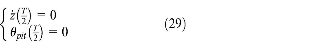
It can be observed from equation (29) that the highest point of the torso’s COM is at the position of the middle of a gait cycle. At the same time, the pitch angle of the torso is equal to zero. That is, when the trunk is in a horizontal position, the COM reaches the highest point. The criterion for stability of the bounding gait is thus obtained: at the highest point in the vertical direction, the torso pitch angle is equal to zero.
This can be expressed as shown equation (30)

In the actual situation, it is impossible to achieve such an ideal state every time. Hence, in order to measure the level of stability of the bounding gait, a new variable ε is introduced as a stability evaluation parameter
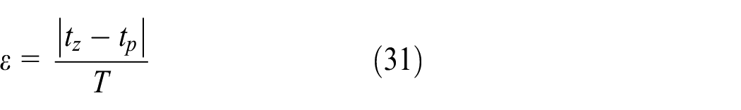
where tz and tp represent the time when the vertical height of the torso’s COM reaches the highest point and the pitch angle in the flight phase is equal to zero, respectively. And we can get
Results
Simulation results
The simulation in this article is performed using MATLAB and Adams software. The parameters of the specific simulation model are shown in Table 2. Figures 6 and 7 show the motion in the simulation. For comparison, a simulation with an active head and a fixed head is provided, and the simulation results are shown in Figures 6 and 7, respectively.
Parameters of the simulation model.

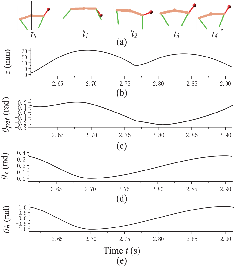
Bounding with an active head: (a) the simulation animation, (b) the vertical displacement of the torso’s COM z, (c) the torso pitch angle θpit, (d) the spine angle θs, and (e) the head swing angle θh.
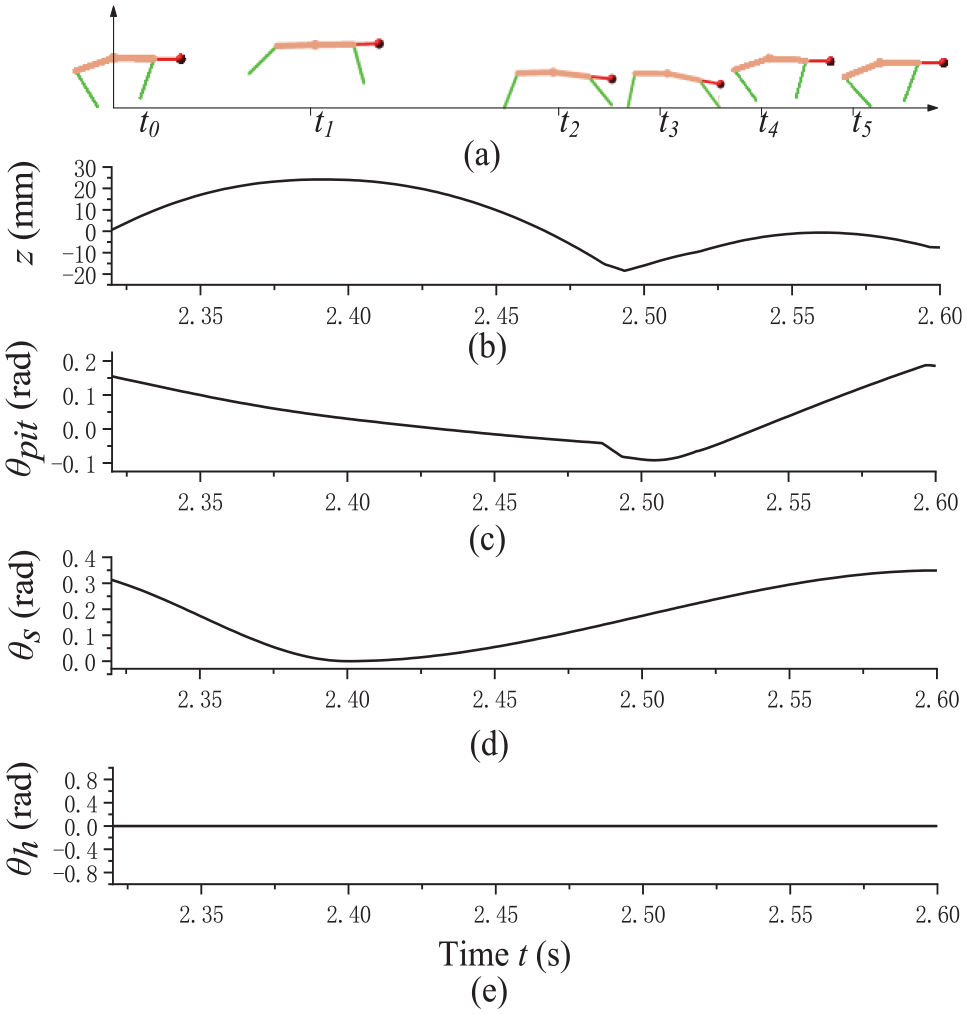
Bounding with a fixed head: (a) the simulation animation, (b) the vertical displacement of the torso’s COM z, (c) the torso pitch angle θpit, (d) the spine angle θs, and (e) the head swing angle θh.
Figure 6 (a)–(e) presents the simulation animation, the vertical displacement of the torso’s COM z, the torso pitch angle θpit, the spine angle θs, and the head swing angle θh, respectively. At time t1, the COM reaches its highest position, while the torso pitch angle is close to zero. At time t3, the COM reaches its highest point in the contracted flight phase, and the pitch angle is close to zero. According to the analysis in the previous sections, the motion shown in Figure 6 meets the requirements of the stable motion criterion and achieves stable periodic motion. Figure 7 shows the bounding gait with a fixed head. The head only acts as an additional weight, causing the overall COM to move forward. t2 is the end time of the extended flight phase. At this time, the pitch angle is too small and the contraction of the spinal joint causes the decrease of the height of the hip joint. These factors cause the hindfoot to touch the ground before the forefoot. In the subsequent phase, the front and rear feet collided with the ground several times. Under the same conditions, the bounding gait with a fixed head is unstable. When the head of the simulation model is active as shown in Figure 6, the average velocity is 0.92 m s−1, and when the head is fixed as shown in Figure 7, the average velocity is 0.67 m s−1. This is mainly due to the unstable movement of the fixed head under the same gait parameters, resulting in an uneven step size.
From the previous simulation results, the highest point of the bounding gait always occurs in the extended flight phase. Directly related to the extended flight phase are the rear leg touchdown angle and the rotation of the spinal joint. The touchdown angle of the leg has a great influence on the bounding height and pitch angle of the quadruped robot. 18 Therefore, the rear leg touchdown angle is taken as a variable. The performance parameters of the quadruped robot under different rear leg touchdown angles are compared. The results are shown in Figures 8–10.
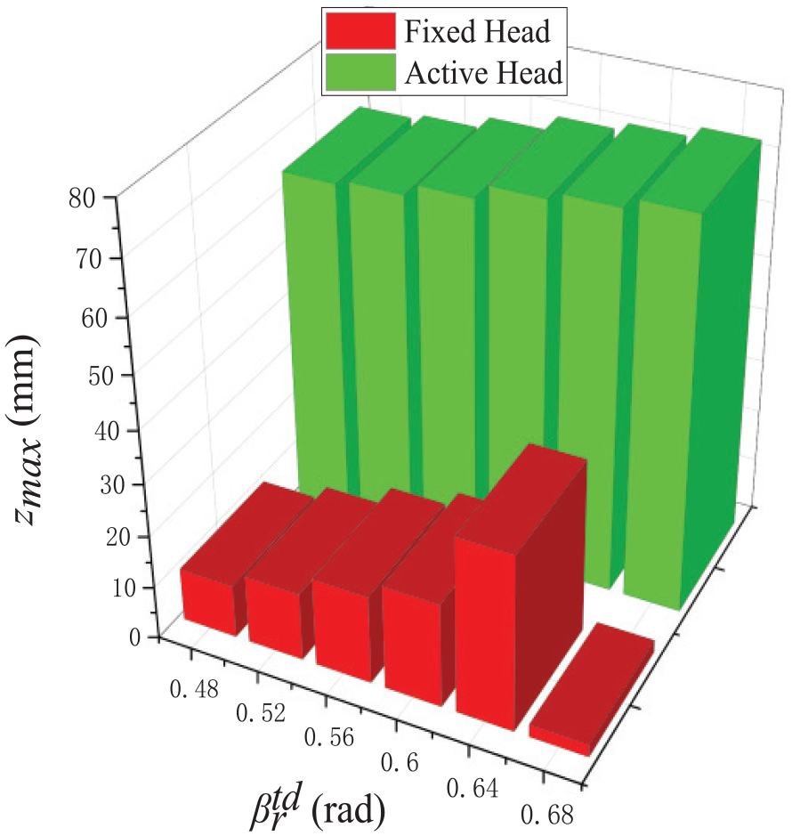
The highest point of the torso’s COM.

Single cycle step size.
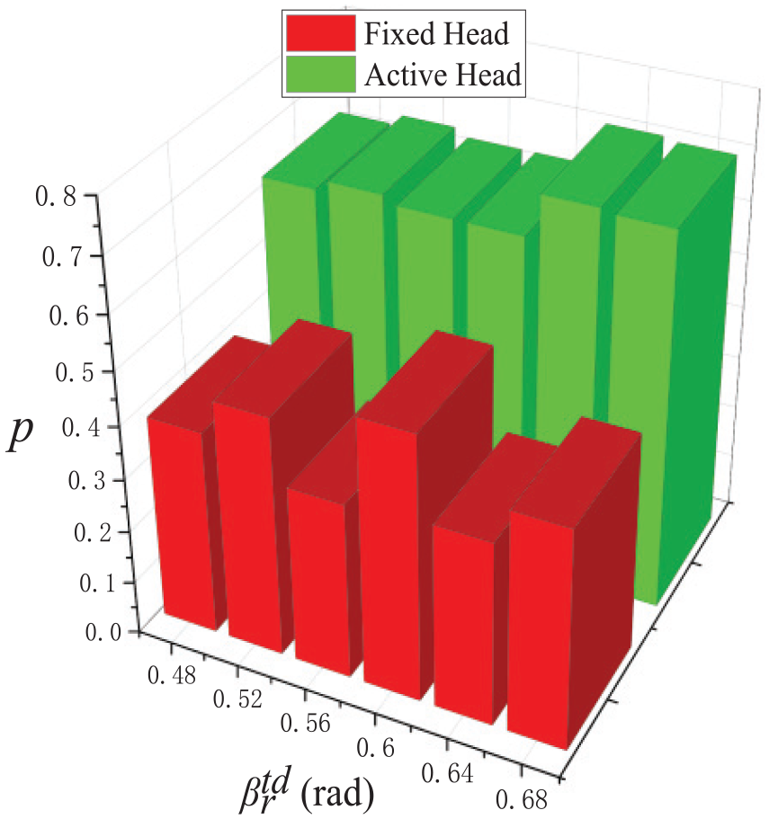
Ratio of the flight time to cycle time in one cycle.
The rear leg touchdown angles are varied from 0.48 to 0.68 rad. In these figures, the green histogram represents the motion with an active head and the red histogram represents the motion with a fixed head. In order to exclude other factors, we select the first period from still to jump as the analysis object. The initial touchdown angles of the front and rear legs are set to be the same.
Figure 8 shows the change in the highest point of the COM of the torso in the bounding gait with the variation of the touchdown angles. It can be seen from Figure 8 that, within a certain range, as the touchdown angles increase, the maximum height of the trunk shows an upward trend. For the maximum height, the model with an active head is much larger than the one with a fixed head. This means that a quadruped robot with an active head can achieve a higher jump height.
Figure 9 shows the variation of the step size in a cycle with the change in the touchdown angles. As shown in Figure 9, the step size of the model with an active head in one cycle is less affected by the change of the touchdown angles. In contrast, the periodic step size of a model with a fixed head fluctuates greatly with the change of the touchdown angles. This means that the addition of an active head gives the robot system greater adaptability. The effect of landing conditions is reduced in the bounding gait.
Figure 10 shows the variation of the ratio of the flight time to the cycle time of the model with the change of the touchdown angles. As shown in the figure, the addition of an active head movement improves the air time of the quadruped robot in the bounding gait. This is good for jumping higher altitudes and getting more time to adjust the trunk and leg state before landing.
For the problem of bounding stability, we proposed parameter ε as the evaluation index in the previous chapters, as shown in equation (31). In the simulation, the statistical results of ε are shown in Table 3. We can see that when the head is fixed, the value of ε is larger and the motion of the simulation model is very unstable. By adding active head movement, as shown in Table 3, the value of ε remains around 0.1. By means of the head adjustment, the unstable movement of the quadruped robot becomes stable.
Periodic stability parameter ε in the simulation.

Experimental setup
In order to verify that the role of the head is equally effective in the actual situation, we designed a simplified experimental prototype Malinois-robot, shown in Figure 11. The design of this prototype is based on the robot we have developed previously. 21 And some excellent quadruped robots’ designs22,23 are adopted. The robot is built mainly from three-dimensionally (3D) printed ABS (acrylonitrile butadiene styrene) plastic, bakelite board. So the weight of the robot is very less. It includes 10 active DOFs (two per leg, one at the spine, one at the head), with direct current (DC) servo motors as actuators. Each leg is actuated by two DC servo motors mounted on the trunk. The knee motor drives the knee joint through a cable mechanism.

Experimental prototype Malinois-robot: (a) side view of Malinois-robot, and (b) side view at CAD presentation of the prototype.
There are many holes in the head component, which is mainly used to fix the clump weight. Different weights can be replaced at the front end of the head. Its design specification is listed in Table 4.
Parameters of the quadruped robot.

The experimental environment is shown in Figure 12, which mainly includes the prototype Malinois-robot, a pedestal with a spherical pivot, a power supply, and a PC. The robot is connected to the passive spherical pivot via a long rod. So the robot can move around the pedestal. The controller of the robot is programmed in the PC. A microprocessor (STM32F103ZET6), installed on the body of the robot, is used to drive DC servo motors and process signals of the sensors. The microprocessor can communicate with the PC via an RS232 interface.

Experimental environment.
The robot is equipped with pitch inclinometers on the trunk to acquire the pitch angle. In the horizontal axis of the passive spherical pivot, there is an incremental photoelectric encoder. Using the incremental photoelectric encoder, we can calculate the vertical displacement of the robot based on the following equation

where z is the vertical displacement, R is the rotational radius (1.5 m), and θ is the rotational angle to the horizontal axis.
Experimental result analysis
Stable periodic bounding motion
In the previous sections, we studied the periodic bounding gait of a quadruped robot with the head and spine, and summarized the coordination relationship between head movement and spine movement. After adjusting in the physical experiment, the value of ε, designed by equation (31), in the bounding gait of the robot can be stabilized within 0.2. The experimental results show that the prototype achieves a stable bounding motion as shown in Figure 13. In the experiment, the average speed of the robot can reach 0.66 m s−1. Considering that the total length of the robot prototype is only about 0.28 m, the speed is satisfactorily enough.

Snapshots of the bounding gait of the robot.
Effect of the head parameters
We designed two experiments. One experiment was to change the head mass without changing the other parameters, in order to verify the effect of head mass on the motion performance of a quadruped robot. Another experiment was to change the length of the head without changing the other parameters, in order to verify the effect of head length on the motion performance of a quadruped robot. The way we change the length of the head is not to replace the head component. It is changing the position of the head clump weight. There are many holes in the head component. By fixing different clump weights at different holes, the quality and length of the head can be changed.
Figures 14 and 15 show the results of the first experiment. The weight of the head ranged from 0.06 to 0.30 kg. The head length is constant at 95.5 mm. As shown in Figure 14, the maximum height of COM increases with the increase of head weight. However, a too large head mass will reduce the stability of the movement, such as when the head mass is 0.30 kg, the movement will fluctuate greatly. As shown in Figure 15, the larger the head mass, the more drastic the variation of the pitch angle. That is, the larger the head mass is, the more obvious the intervention effect of head motion on quadruped robot motion will be.

Variation of the robot vertical displacement with different head weights.
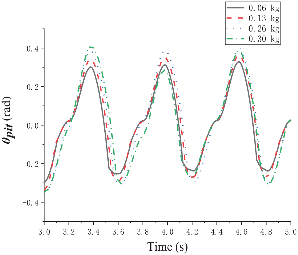
Variation of the torso pitch angle with different head weights.
Figures 16 and 17 show the results of the second experiment. In the experiment, the mass of the head remained unchanged, constant at 0.26 kg, and the length of the head changed from 58 to 95.5 mm. From Figures 16 and 17, it can be seen that the longer the head length is, the higher the maximum height of the COM is and the more violent the pitch angle of the trunk changes. That is, the longer the head length, the more obvious the intervention effect of head movement on the performance. However, the head length is limited by the overall size of the structure. If the head is too long, the more likely it will collide with the ground. The larger the head mass and the longer the length, the greater the driving torque required, which is another important factor that limits the head weight and size.
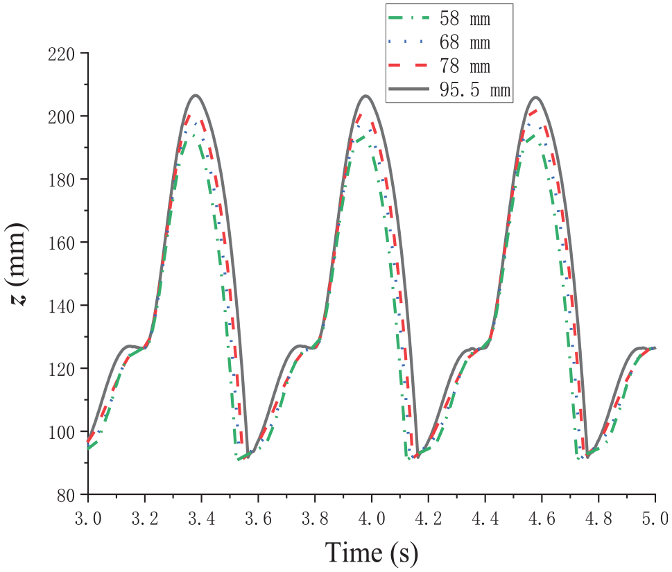
Variation of the robot vertical displacement with different head lengths.

Variation of the torso pitch angle with different head lengths.
Discussion
Other studies on the movement of the head are mainly for the purpose of visual stability. CP Santos et al. 14 have mainly studied how to reduce the shaking of the head due to the movement of the body, since cameras have to be mounted on the head of the autonomous quadruped robots. The purpose of this article is to improve the motion performance of quadruped robots by active head movement. XL Zhang et al. 12 studied the effects of head and tail appendages on a quadruped robot with a rigid trunk. The research object of this article is a quadruped robot with an active spine. The motion is more complex because of the joining of the spine motion, which is also the reason for the instability of quadruped robots with the spine. Therefore, this study has more practical significance. Moreover, the study in this article attributes the influence of head to the position of the COM and the regulation of trunk pitch motion. This provides a further explanation for the mechanism of head movement in quadrupeds.
The swing motion of the head has different initial positions and swing amplitudes. These two factors have a great impact on the performance of the quadruped robot. In this article, we set the initial position of the head at 0.96 rad, and the amplitude of the swing is 2.09, 2.62, 3.05, and 3.14 rad. The pitching motion of the torso can be attributed to the pitch angle and the pitch angle velocity. This requires us to find an optimization algorithm to calculate the optimal parameters of head swing under different torso pitch states. This is also the problem we will solve in the future.
We are studying the motion of a quadruped robot in the sagittal plane. We chose the pitch angle of the torso and the height of COM as the main research objects. These two parameters can represent the motion state of the robot in the sagittal plane. We set the movement of the quadruped robot to start from rest. In this way, we can ignore the impact of the initial speed on the quadruped robot. Leg stiffness is an important parameter for quadruped robots. Because our research focuses on the movement of the head, the interference of other factors need to be ignored. In the simulation experiments in this article, we used rigid rods to replace the legs. This is equivalent to assuming that the elastic coefficient of the legs is infinite. In the physical experiment, the Malinois-robot adopts the design of spring legs. This design can reduce the impact between the legs and ground and improve the adaptability to the terrain.
Conclusion
The bounding gait of the quadruped robots is used primarily to cross obstacles. So the height of bounding and stability of landing are the major research objects. This article provides a new way to tackle these problems: by adding a head appendage to improve the bounding performance and stability. Through theoretical analysis, we obtain the function of the head appendage. First, the head can realize the active control of the COM position of the robot, which is of great significance to the stable motion of the robot. Second, head’s swing motion can be used as a means to adjust the pitching motion of the trunk. A criterion to assess the stability of the bounding gait is obtained by symmetry principles. The shorter the time between the highest position of COM and the zero pitch angle, the more stable the bounding motion will be. Subsequently, the movement of the head in a periodic bounding gait is summarized. Through simulation and experiment, we verified some relevant conclusions. Head movement can indeed improve the bounding performance and stability. And the head structural parameters (head weight and length) have a great impact on the degree of adjusting effect. The larger the head weight, the longer the head length and the more obvious the head adjusting effect. In the follow-up research, we need to study the movement parameters of the head, such as swing amplitude and speed, and explore the role of the head appendage in other gaits. Eventually, a quadruped robot that can move outdoors will be developed.
Footnotes
Handling Editor: James Baldwin
Declaration of conflicting interests
The author(s) declared no potential conflicts of interest with respect to the research, authorship, and/or publication of this article.
Funding
The author(s) disclosed receipt of the following financial support for the research, authorship, and/or publication of this article: This work was supported in part by the National Natural Science Foundation of China (Grant No. 51205075) and the Fundamental Research Funds for the Central Universities (Grant No. 3072019CF0703).
Supplemental material
Supplemental material for this article is available online.
References
Supplementary Material
Please find the following supplemental material available below.
For Open Access articles published under a Creative Commons License, all supplemental material carries the same license as the article it is associated with.
For non-Open Access articles published, all supplemental material carries a non-exclusive license, and permission requests for re-use of supplemental material or any part of supplemental material shall be sent directly to the copyright owner as specified in the copyright notice associated with the article.