
Abstract
The central pattern generator (CPG) has been found to be a real, existing neuron controller for the locomotion control of animals and it has been used on bio-inspired robots widely in recent years. However, research on the adaptability of CPG-based locomotion control methods is still a challenge. In particular, the performance of the CPG method on quadruped robots is not good enough in some situations compared with the traditional force control methods.
In this article, we adopt a CPG method in which phase difference between oscillators can be arbitrarily adjusted, and we try to improve the CPG's applications in quadruped robots in some aspects. One aspect is static walk gait locomotion, in which we try to add a transition state in the CPG network to enhance the static balance of the robot. Another aspect is gait transition. Compared with the traditional abrupt gait transition, we try to realize a continuous gait transition between walk gait and trot gait to decrease the fluctuations of the robot. The improved CPG method is tested on a quadruped model and it shows positive results with regard to the improvement of static walk gait and gait transitions.
1. Introduction
Most species in the terrestrial world employ legged locomotion and can perform diverse behaviours. This is believed to be the result of natural selection and evolution. In contrast, the locomotion control of legged robots is still challenging, as it contains many subsystems such as mechanics, environmental sensing, control algorithms, etc. Several years ago, bionics was carried out from the viewpoint of mechanics, i.e., to design bio-inspired legs [1]. While in recent years, researchers have developed central neural systems (CNS) as a more appropriate way of controlling robots. CPG, directly inspired by the animal's neural systems, has been proposed to serve as the main controller of legged robots [2–4].
Biologically, CPG is a distributed neural network, located in the spinal cord of vertebrates, able to generate complex high dimensional signals for the control of coordinated periodic movements [5]. CPG neuron circuits can be modelled as connectionist models [6], vector maps [7], and mostly oscillators [8,9]. With a special structure, the coupled oscillators can produce rhythmic signals regardless of the initial value, i.e., the system is stable, making CPG-based locomotion controllers suitable for legged robots. In addition, they offer some other advantages: the oscillating amplitude and frequency can be easily adjusted to realize different step lengths and velocities of the robot; the phase differences between neurons can be set to different values in order to generate different gaits; CPG circuits can be easily coupled by sensory inputs. In a word, CPG-based locomotion control is becoming increasingly popular compared with the traditional modelling and planning methods.
Research on CPG-based locomotion control for legged robots has made great progress since the 1990s. G. Taga et al. carried out pioneering work on biped robots using CPG-based controllers [10]. H. Kimura et al. have been working on the locomotion control of quadruped robots for many years and their contributions can be found in [11–13]. For hexapod robots or octopod robots inspired by insects, such algorithms are also effective [14, 15]. A. J. Ijspeert et al. have made exciting progress in different aspects of CPG-based locomotion control, including the CPG framework, feedback of sensor information, coupling with the mechanics and gait transitions, etc. [16–18]. The works of the lamprey-like swimming robot published in [19] are also very impressive.
Despite the past efforts made by researchers in this field, there are still problems to be solved. In quadruped locomotion, the COG and posture control cannot be neglected as gravity dominates the movement, especially at low speed. Posture control methods (control of COG and zero moment point (ZMP)) determine movement performance [20, 21]. However, CPG has only been used to generate synergetic rhythmic movements among limbs (or joints), posture balance control has not been into account. Thus, during a limb's phase transition from stance phase to swing phase, or a gait transition from one gait to another gait, this may result in sudden COG changes and loss of balance for the robot. For example, when the robot transforms its swing limb from front limb to hind limb in a gait, the hind limb sometimes cannot lift as COG has not moved into the supporting triangle.
Some strategies to cope with the problem have already been developed. One strategy, from the control aspect, is to use a transition state where all limbs are in the support phase when moving the COG into a stable region, i.e., incorporating a state where all the limbs are on the ground before the hind limbs lift up. A typical application of this strategy is published by LittleDog [22, 23]. Another strategy is to change the mechanics of the robot, such as using head motion to balance the body [24]. These strategies are effective, but require a precise mechanical model of the robot and calculation on the trajectory of all joints and COG, which makes the process very complicated.
Applying CPG-based locomotion control may be a potential alternative to resolving this problem as it does not require calculating the precise mechanical models of the robot. However, there is little existing research which depicts how to enrol COG control into CPG-based methods.
In this paper, we adopt a method of constructing CPGs which is derived from [16]. In differential equations which represent the CPGs' functions, the coupling relationship between neurons is formulated by a continuous item instead of discrete matrices. The improved CPG has the following important advantages: firstly and most importantly, the phase differences between neurons can be set to arbitrary values. Hence the CPG can generate diverse gaits other than limited gaits as with the existing CPG methods. Secondly, the neurons have diverse stance frequency and swing frequency. This feature is important because the stance frequency and the swing frequency are usually different and adjustable in many applications in order to achieve different velocities and maintain a specific gait.
The problem of COG control can be addressed by our proposed CPG-based locomotion control method. To avoid the situation where the robot loses balance and the hind limbs fail to lift from the ground in a gait, a transition state was added in the gait. In this transition state, the hind limb will not lift up immediately after the diagonally opposite forelimb touches the ground. During this period, the other three limbs continue moving in the stance phase. Thus there is a special transition state where all four limbs are in the stance phase and propelling the robot forward. The COG of the quadruped robot will move into the support triangle during the transition state. The offset of COG depends on the duration of the transition state. If the COG's offset is long enough into the triangular stable region generated by the stance limbs, the robot will not lose balance when a hind limb lifts up. Obviously, the introduction of the transition state makes our present gait pattern different from the typical regular gaits.
Meanwhile, smooth and gradual gait transitions can also be realized with the special structure of our CPG models in which the phase differences between neurons can be continuously adjusted. Gait transition is very important for legged animals during their locomotion process. Different gaits are applied to different velocities, energy consumption and environments. T. G. Brown has done experiments on decerebrated cats [26]. The decerebrated cat showed gradual and smooth gait transitions from walk to trot and even gallop when the treadmill is accelerated [27]. A gradual transition process is very beneficial for the posture's compliance and balance of the robot compared with an abrupt gait transition. In a gradual gait transition, the phase difference between oscillators changes regularly, thus it can decrease the fluctuations of the posture. However, in existing CPG methods, the CPG network for different gaits (or the phase differences between the oscillators) transits abruptly because the parameters representing phase relationships between oscillators are discrete matrices, and for this reason it cannot gradually modulate phase relationships between the oscillators. The proposed method of constructing CPGs is able to modulate the phase differences among all oscillators by using one parameter. A specific value of this parameter can represent a specific gait. When this parameter's value is changed gradually, smooth gait transitions can be achieved.
The structure of our paper is arranged as follows. In Section 2, we present the new method of constructing the generic CPG model in detail. In Section 3, we describe the CPG control framework for quadruped robots. In this section, improvement of the trajectories of COG in a static walk gait is discussed; in addition, we illustrate how the gait transition process becomes smoother using our proposed CPG method. Overviews of the mechanical structure of our quadruped robot and the simulation environment are described in Section 4. The simulation, discussions of different CPG methods and results analysis are shown in Section 5. Finally, conclusions are drawn and our future works are planned in Section 6.
2. CPG architecture
2.1 Oscillator model
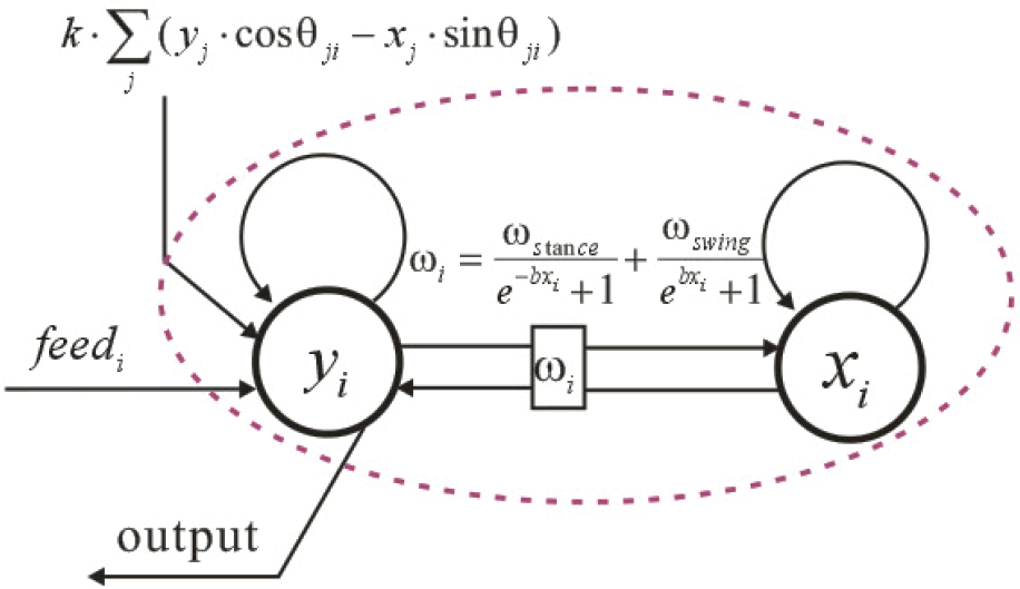
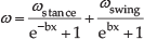
The basic requirement of an oscillator model is that it can produce a steady periodic signal, i.e., it can generate a steady limit cycle in the phase space. An improved Hopf oscillator from nonlinear dynamics which was modified by L. Righetti and A. J. Ijspeert is used as the oscillator model for constructing CPGs [16]. The equations are as follows:


where, x and y are two state variables of the oscillator.

A Hopf oscillator's limit cycle behaviour. (a) y as a function of time. y has different ascending frequency and descending frequencies. In fact we set ωascending =4ωdescending, because we intend to use the ascending process and the descending process to represent the swing phase and the stance phase respectively; (b) the relationship of x and y in the phase space when the oscillators have different initial values. The red points are different initial values of the variables. The oscillators can generate a steady limit cycle regardless of different initial values except for the value of (0, 0).
Fig. 1 shows the improved Hopf oscillator's limit cycle behaviour. y is used as the output of the oscillator (or the neuron). Fig. 1(a) shows that the oscillator's frequency varies between the ascending phase and the descending phase. The configuration which causes different frequency in the ascending process and the descending process is very useful in some situations. For example, for quadrupeds, the swing phase and the stance phase take different amounts of time in a period of walk gait. If the ascending process and the descending process are used to represent the swing phase and the stance phase respectively, their frequencies must be set to different values. Fig. 1(b) shows that the limit cycle is steady regardless of the initial value (except the initial value of (0, 0)).
2.2 CPGs' network
A special polynomial is added to the above oscillator model so that it generates a coupling relationship with other oscillators. These oscillators will generate specified phase differences by the set values. In addition, considering the feedback from the sensor information, the method of adding sensor information feedback has been shown in [12, 16, 28, 29]. Thus, the CPGs' network can be depicted by the equations below. Its structure can be seen in Fig. 2.
The structure of an oscillator with the coupling relationship and the feedback of sensor information.


Comparing Equation 5 with Equation 2, the main difference is that Equation 5 contains a special polynomial:

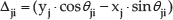
in which, φ˜i and φ˜j represent Oscillator i and Oscillator j's reference phase respectively. Fig. 3 shows the proposed CPGs' features.

The CPG network formed by two oscillators under different phase difference settings. The phase difference θ12 equals to
From Fig. 3, it can be seen that the CPG can maintain the predetermined phase difference between the oscillators. In fact, the phase difference can be set to any arbitrary value. Though, the CPG only contains two oscillators in this example, the proposed method of designing CPGs can be successfully applied to CPGs which contain more oscillators. In addition, with the function of setting different ascending frequency and descending frequency, the proposed method of constructing CPGs can be applied to many CPGs control applications. In this paper, we ascertained a method of constructing CPGs specifically for solving the problem of a robot losing balance (cannot lift the hind limbs) as described earlier. The details of the applications of the proposed CPG method can be found in the following sections.
3. CPG control framework for quadruped robots
3.1 CPG control network
A general model of the CPG control method for locomotion is shown in Fig. 4. The control effect of the senior nerve centre is complex locomotion and moving forward to a destination with various sensor information, such as posture information, vision information, etc. CPG controls inflexions and extensions of body parts by generating periodical signals which have some typical features, such as frequency and amplitude as shown in Fig. 4. CPG is generated by coupled neurons (oscillators) whereby different coupling relationships represent different gaits. The motor behaviours are obtained by mapping functions from the CPG's output to realize the robot's locomotion.

A general control architecture of the CPG method.
Although sensor information is very important in the CPG control method, the basic rhythmical locomotion of limbs and some other body parts neither directly result from the output instructions of the senior nerve centre, nor rely on the input of sensor information. It is generated by the CPG which is located in the spinal cord. So in this article we do not concentrate on the incorporation of the sensor information but on the improvement of the CPG's structure.
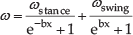
Usually, the mechanics of limbs for quadruped robots are designed as follows: each limb contains two DOFs in the hip joint and one DOF in the knee joint. To simplify the CPG control network, four oscillators are used to control locomotion of four limbs respectively. Hence the CPG's network is the coupling of four oscillators. The control signals for the hip joint and knee joint are mapping functions of the original output of the CPG. The network of the CPG for quadruped robots can be constructed as shown in Fig. 5. The four oscillators generate coupling relationships by the polynomial as mentioned in Section 2. In Fig. 5, Δji represents the polynomial.

The network of CPG for quadruped robots. Limb 1 represents the left forelimb (LF). Limb 2 represents the right forelimb (RF). Limb 3 represents the right hind limb (RH). Limb 4 represents the left hind limb (LH). All oscillators are coupled with each other by the use of Δji (for quadruped robots, i, j = 1, 2, 3, 4, and i ≠ j).
Multi-legged robots have generally two or more types of gaits. Different kinds of gaits have different phase relationships among oscillators. For quadrupeds, there are five kinds of typical gaits: walk, trot, pace, gallop and bound. However, the study of these gaits' functions for the locomotion of quadruped robots has revealed some drawbacks of the existing CPG methods on locomotion control. One problem is how to integrate COG control into CPG networks to avoid losing balance. Another problem is how to realize a gradual and smooth gait transition to decrease fluctuations of COG during gait transitions. The following two subsections address these two problems by applying the proposed CPG algorithm.
3.2 Modulation of COG in static walk gait
Fig. 6 shows the typical walk gait using a bar diagram. It demonstrates that d (or duty factor: the proportion of stance phase's duration in a gait period.) equals 0.75. The phase differences between the oscillators are very regular, i.e., that the phase advance of one swing limb to its successor is

The bar diagram of the typical walk gait. The black sections stand for the swing phase and the white sections stand for the stance phase. d = 0.75.
One problem is that the robot may lose balance when a hind limb lifts up as the COG of the robot is out of the stable region. Fig. 7 demonstrates the condition for static balance. In Fig. 7, Limb 1 has just completed its swing phase and reached the stance phase. At this point, Limb 2 and Limb 4 continue moving in the stance phase and Limb 3 is about to go to the swing phase. On this occasion, to ensure the robot's posture balance when Limb 3 lifts up, the COG's projection in the horizontal plane must be in the stable region which is generated by the three stance limbs (Limb 1, Limb 2 and Limb 4) shown by the green area in Fig. 7. This is also called the condition for static balance.

The condition for static balance. Z coordinate and X coordinate represents the forward direction and the lateral direction respectively. P1, P2, P3 and P4 are the footholds of the four limbs. The constrained reachable area (CRA) is defined as a rectangular area in the intersection of the support plane and the foothold kinematic working volume [30]. As a quadruped robot moves in a walk gait at low speed, the COG's projection in the horizontal plane must be in the triangular region generated by the three stance limbs for balance.
While the CPG algorithm for locomotion control has ignored the mechanical systems and planning of the COG's trajectories, the locomotion control method using CPGs cannot ensure that the COG is in the stable region. For a quadruped robot with a symmetrical structure and all limbs the same step length, if the static walk gait (as illustrated in Fig. 6) is adopted (in which Limb 3 must lift up immediately when Limb 1 touches the ground), there is a high risk that the COG is not in the stable region. Therefore, the walk gait described in Fig. 6 is not a desirable walk gait as it cannot cope with all applications.
However, this problem of COG control can be solved if a transition state is inserted between the moment Limb 1 touches the ground and the moment Limb 3 lifts up. In other words, Limb 3 should not lift up immediately when Limb 1 touches the ground. During the transition state, all four limbs continue moving in the stance phase by controlling the joints. Thus, the body trunk will move forward due to the combined action of four stance limbs. Therefore, COG can be moved forward into the stable region before Limb 3 lifts up, thus the robot will not lose balance when Limb 3 lifts up. In locomotion, there is no doubt that stance limbs and swing limbs work together to drive the robot forward. When a limb is in stance phase, the foot stands still, but the thigh and the shank will move forward by the joints' motion in the hip and the knee. When all limbs are continuing moving in the stance phase, the body trunk and the COG will move forward. Fig. 8 shows the function of the transition state.

The moving tendency of the limbs and the body trunk when all limbs are in stance phase. The X coordinate, Y coordinate and Z coordinate represent the lateral direction, the vertical direction and the forward direction respectively. The stable region is generated by the three support limbs. The quadruped model which is drawn in black shows the COG's status before the transition state; the quadruped model which was drawn in red shows the COG's status after the transition state.
In order to insert the transition state in a gait period, the walk gait illustrated in Fig. 6 must be modified. Fig. 9 illustrates the improved walk gait using a bar diagram. From Fig. 9, it can be seen that the duration of the swing phase for all limbs is the same. But there are two transition states in which all limbs are in stance phase. The two transition states are both inserted at the moment before the hind limbs (Limb 2 and Limb 4) lift up. Due to this configuration, the phase differences between the limbs become irregular (the phase difference between one swing limb and its successor is not
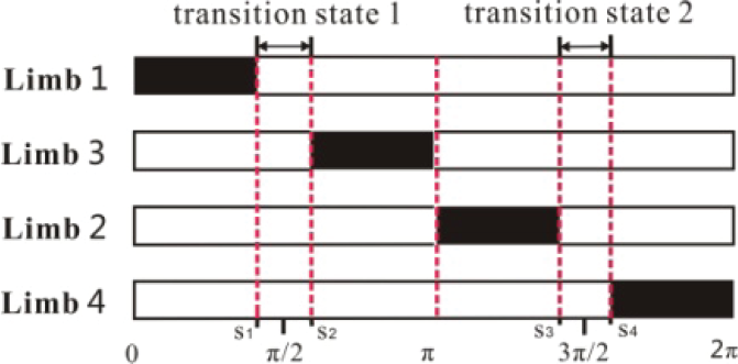
The bar diagram of the improved walk gait. The black sections stand for the swing phase and the white sections stand for the stance phase. In the transition state, all limbs are in the stance phase. d > 0.75.
If we define S1 = 80°, S2 = 100°, S3 = 260° and S4 = 280°, as shown in Fig. 9, it means that both of the two transition states last

When these phase differences are put into the CPG network in Equations 4,5,6,7, the simulation result can be seen in Fig. 10.

The CPG output curves of a static walk gait. The ascending process and descending process of the curves respectively represent the swing phase and the stance phase. There are two transition states where all four limbs are in the stance phase in a gait period.
From Fig. 10, one can see that the phase difference between Limb 1 and Limb 3 (or the phase difference between Limb 2 and Limb 4) is larger than the phase difference between Limb 2 and Limb 3 (or the phase difference between Limb 1 and Limb 4) because of the incorporation of the transition state. One can also see that the real phase differences are equal to the set values in Equation 9. So the proposed method of constructing CPGs has been successfully applied to a CPG containing four oscillators. This example also proves the validity of the CPG construction.
3.3 Smooth gait transitions
No matter whether in walk gait or trot gait, the phase difference between the contralateral limbs (the phase difference between Limb 1 and Limb 2, as well as the phase difference between Limb 3 and Limb 4) is a fixed value: π. The main difference between walk gait and trot gait is the phase difference between the two diagonally opposite limbs (the phase difference between Limb 1 and Limb 3, as well as the phase difference between Limb 2 and Limb 4). When the phase difference between the diagonally opposite limbs is
In Equation 10, θ˜13 is the reference value of the phase difference between Limb 1 and Limb 3. Its value is set when executing a specific gait. When θ˜13 is changed gradually, a gradual and smooth gait transition can be realized.

As walk gait is applied to locomotion at low speed and trot gait is applied to locomotion at higher speed, velocity should also be modulated during gait transition from walk to trot. To transform from low speed to high speed, the frequency of both stance limbs and swing limbs is accelerated. The acceleration of the stance limbs plays a dominate role in this transformation and this discipline corresponds with the acceleration of legged animals. In a word, during gait transition from walk to trot, θ˜13 should become smaller (from


in which, m is a free parameter, the value of m is increasing during gait transition to avoid ω

The CPG output curves of a smooth gait transition. The gait changes from a static walk gait to a fast walk gait, and finally to a trot gait. The phase difference between Limb 1 and Limb 3 (or the phase difference between Limb 2 and Limb 4) becomes smaller and smaller, eventually reaching zero. The transition process is gradual and smooth.
From Fig. 11, one can see that the gait changes gradually and smoothly from a static walk gait (d > 0.75) to a fast walk gait (0.75 > d > 0.5), and finally a trot gait (d = 0.5). Meanwhile, the oscillators' frequency becomes smaller and smaller. ωstance is smaller than ωswing in the walk gait, but both of them increase during gait transition, and finally their values become equal in the trot gait.
4. Simulation model and environment
4.1 Mechanical model
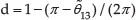
Fig. 12 shows the quadruped robot model for simulations. The quadruped model was designed using SolidWorks.
A quadruped robot model.
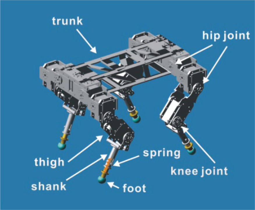
It contains a trunk and four limbs. Each limb contains three segments: thigh, shank and foot. There are three DOFs on each limb. The first one is on the shoulder part (hip), and it controls movement in the lateral direction. The second one is also on the shoulder part, but it is used to control movement in the forward direction. The third one is the knee joint, which controls movement in the forward direction together with the second DOF on the shoulder part. All the three DOFs are actuated by a modular actuator (a digital servo motor). The feet are made from a spherical rubber section to maintain enough friction force with the ground. The foot and the shank are connected by a spring, which ensures a compliant reaction with the ground and decreases the impact force the robot is subjected to during the transition between the stance phase and the swing phase. The dimensions of the main parts of the quadruped model are shown in Table 1.
Dimensions of the main parts of the quadruped model.
It can be seen that the quadruped robot adopts a typically symmetrical structure. This kind of mechanical design deceases the influence of mechanics in the COG control. Such mechanical design was adopted to verify the validity and generality of our method which modulates the trajectories of the COG to avoid losing balance.
4.2 Simulation environment
The simulations are implemented using Adams - a widely used multi-body dynamics and motion analysis software - as it offers excellent dynamics analysis that is essential in the locomotion control of a quadruped robot. The software can simulate the real environment, it also helps to test and optimize our quadruped model, which may lead to a better design of a real quadruped robot in future works.
In the Adams simulation environment, the control of the joint angle is very easy to realize. One just needs to import the joint angle trajectories (the generation of the joint angle trajectories will be described in the next section.), then the joint will be actuated. The servo motor is not used in Adams, but it will be used for the locomotion control of the real quadruped robot which will be constructed afterwards. The simulation process with MATLAB and Adams is shown in Fig. 13.
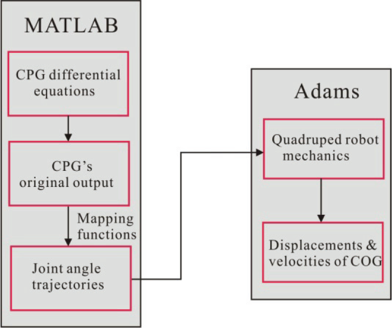
The simulation process with MATLAB and Adams.
5. Simulations and analysis
5.1 Generation of motion behaviours
In this section, the locomotion control effect of the proposed CPG method is verified with the quadruped robot model. The focus is on the second DOF and the third DOF of the limbs because they are the main driving forces for the forward movement. Fig. 14 shows the definition of rotation angles of all joints.

Joint angles of all limbs for forward movement.
In Fig. 14, we define the angles of the hip joint and knee joint in each limb. In order to distinguish the joints in the different parts and different limbs, we use χij to define these angles. i represents the limb index number in χij. When j = 1, it means the angle of the hip joint for forward movement. When j = 2, it means the angle of knee joint.
To obtain the joints' angle trajectories of the quadruped model, the original CPG output curves, as presented in Fig. 10, should be transformed by mapping functions. Since the CPG method is free from the precise modelling of the mechanics and planning of the trajectories, according to the coordinates of our design, we define the joints' workspace as follows: the range of χ11 and χ21 is in the interval [50°, 80°]; the range of χ31 and χ41 is in the interval [−80°, −50°]; the range of χ12 and χ22 is in the interval [100°, 130°]; the range of χ32 and χ42 is in the interval [−130°, −100°].
Fig. 15 shows the principle of designing mapping functions for a limb. When a limb is in the stance phase, the hip joint has the main effect on the limb's movement, while the knee joint rotates on a very small scale (it can be almost regarded as keeping still), and this principle corresponds to the discipline of the locomotion of a quadruped animal; when a limb is in the swing phase, the hip joint and the knee joint take on a synchronous effect. Because the shank should lift up and then put down during the swing phase, a parabola is used to synchronize the hip joint and the knee joint. For example, for Limb 1, mapping functions in Equations 14 and 15 are used to generate the angle trajectories of its two joints.

The locomotion of a limb in the stance phase and the swing phase. The blue dashed lines represent all the body parts at the finish time of the stance phase and the swing phase respectively. The yellow dashed line represents the motion trajectories of the foot for a swing limb.


y1 is one of the original outputs of the CPG which represents the phase of Limb 1, its definition can be seen in Equation 5.
For Limb 2, Limb 3 and Limb 4, the transformation functions can be obtained in a similar fashion. The differential equations of the CPG are calculated in MATLAB and the data of the eight joints' angle trajectories are obtained. Then these data are used to make simulations on the quadruped robot mechanics in Adams software.
5.2 Simulation of COG modulation in static walk gait
Fig. 16 shows the angle curves' phase relationships which reflect our proposed CPG-based control method containing two transition states in a gait period. Fig. 17 shows the comparison of locomotion performance between an existing CPG method and our proposed improved CPG method. The comparison of the control effect between the existing CPG method and the proposed CPG method shows distinguishable differences. The displacement in the forward direction and the lateral direction is smoother using our method. We observe that the robot model cannot move well in the forward direction using the existing method as it loses its balance and cannot lift its hind limbs well from the ground when a hind limb is about to start its swing phase process. The situation where the hind limbs could not lift from the ground was also seen on the Cheetah robot which adopts an existing CPG method [18]. This situation can be greatly improved using our proposed CPG method.

Generation of joint angle trajectories for a static walk gait using the proposed CPG method (this result is generated using a MATLAB simulation). There are two transition states in a gait period to avoid losing balance of the COG in a static walk gait.

Comparison of static walk locomotion control performance between an existing CPG method and our proposed improved CPG method (this result is generated using an Adams simulation). The displacement in the forward direction and the lateral direction is smoother using the proposed method. In fact, moving forward in Fig. 17(a), which uses the existing CPG method, has shown a process whereby the displacement decreased for a while. This is because the existing CPG-based method cannot modulate the COG to the steady region meaning that the quadruped robot fell down backwards.
Fig. 18 shows the quadruped robot's locomotion at a different time of a gait period using the proposed CPG-based control method. In Fig. 18(b) when the time is 2.14s, a transition state starts in which all four limbs are in stance. In Fig. 18(c) when the time is 3.54s, the transition state is completed and a hind limb is about to lift up. In Fig. 18(g) (t=6.72s), another transition state starts and it is completed in Fig. 18(h) (t=7.90s). Every transition state lasts about 1.30s in a gait period.
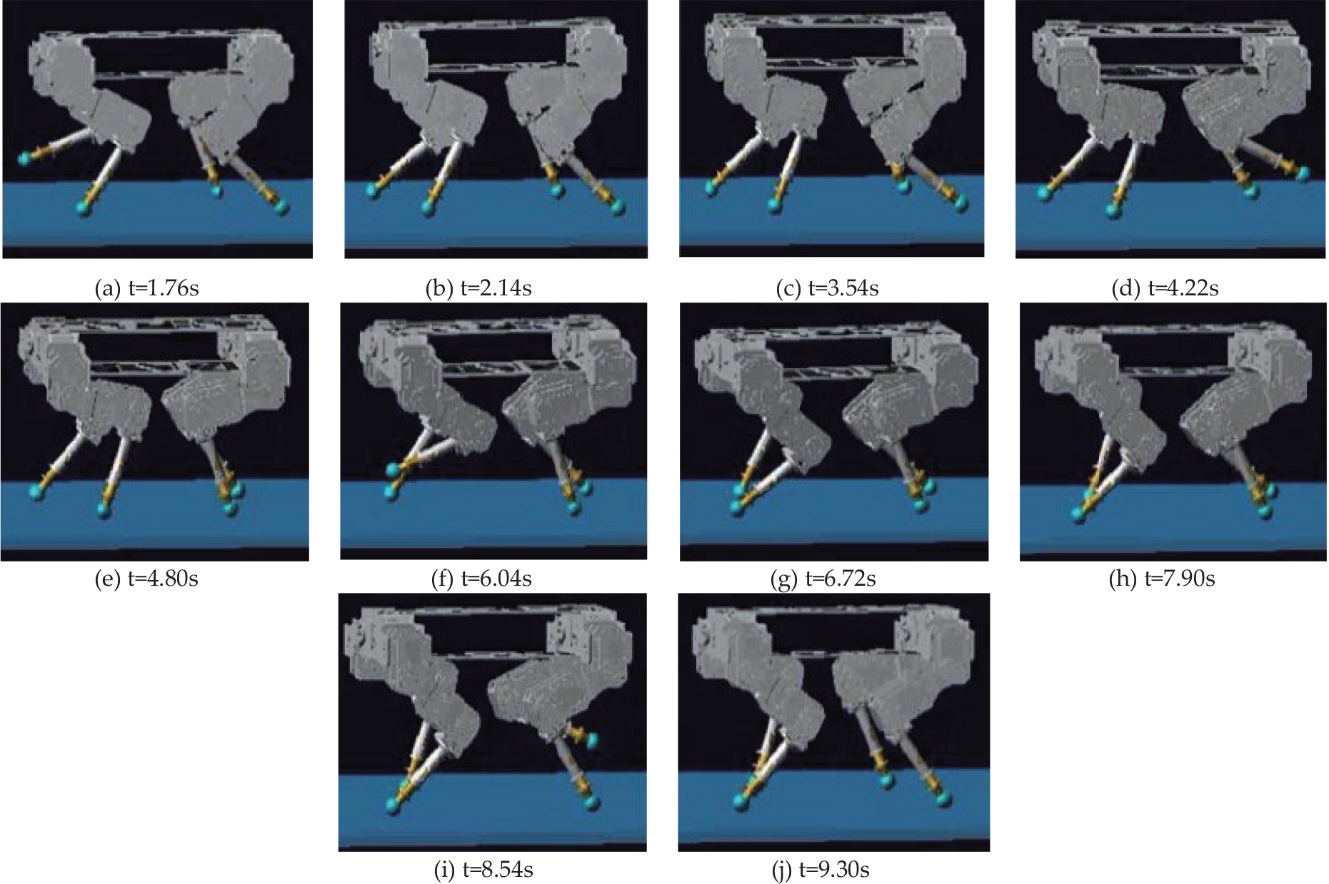
Some pictures of the quadruped robot model in a different time of a gait period (this result is generated using an Adams simulation). (a) Limb 2 is in the swing phase. (b) Limb 2 touches the ground, and the robot starts a transition state. (c) The robot completes the transition state, Limb 4 is about to lift. (d) Limb 4 is in the swing phase. (e) Limb 4 touches the ground, Limb 1 is about to lift. (f) Limb 1 is in the swing phase. (g) Limb 1 touches the ground, and the robot starts another transition state. (h) The robot completes the transition state, Limb 3 is about to lift. (i) Limb 3 is in the swing phase. (j) Limb 3 touches the ground, Limb 2 is about to lift.
5.3 Simulation of smooth gait transition
The motion behaviours of the limbs during gait transition from walk to trot can be obtained by transforming the CPG original output curves in Fig. 11. Fig. 19 shows the joint angle trajectories. It can be seen that the frequencies are set very high in order to achieve a high velocity of the robot, thus the inertial force can overcome gravity and enhance the posture balance of the robot in the fast walk gait and trot gait. Then a simulation of gait transition from walk to trot is executed. Displacement of COG is shown in Fig. 20. The velocity of COG in the forward direction is shown in Fig. 21. In Fig. 20, the COG's displacement in the forward direction during gait transition from walk to trot is smooth. In Fig. 21, the peak value of the velocity of COG in the forward direction is periodically increasing during the transition process. The oscillating frequency of the velocity is also increasing during the transition process.

Generation of joint angle trajectories for smooth gait transition from walk to trot (this result is generated using a MATLAB simulation).

The displacement of COG in the three coordinate axes of the quadruped robot model during gait transition using the proposed CPG method (this result is generated using an Adams simulation).

Velocity of COG in the forward direction (this result is generated using an Adams simulation).
6. Conclusions and future works
In this paper, a CPG which can generate arbitrary phase differences between oscillators to satisfy different requirements is designed. It can be used to generate some transient gait patterns which appear to be more adaptable compared with the existing typical regular gaits. With the improved CPG model, the problem of hind limbs not being able to lift up at the beginning of the swing phase in walk gait is successfully solved. A transient support phase is added so that all four limbs are on the ground to move the COG into the support triangle. In this way, the body balance control is realized. In addition, the proposed CPG method has also shown advantages in gait transitions, a gradual gait transition process can be realized which will make the transition process more compliant and enhance the COG's balance. Such a function is easy to achieve with this kind of CPG algorithm as the coupling relationships between neurons are continuous, compared with discrete coupling items in the existing CPG method.
Our future works include the design of a physical prototype to verify our improved CPG algorithm. Meanwhile, some sensory information is being added into the model to make the movement more adaptive.
Footnotes
7. Acknowledgments
This work was supported by National Natural Science Foundation of China under the project 61175108, and National 863 Program of China under the project 2011AA040902.
The quadruped model was designed by Zhongxiang Zhang and Jingjun Yu. Thanks for their contributions.