
Abstract
Based on field data and the related theories, the effects of drill string length, rotation speed, trajectory, and drilling fluid density on the friction during horizontal well drilling are analyzed in Sichuan. With increasing the length of drill string in the horizontal section, the friction grows. The drill pipe rotates faster and the torque decreases. Large undulation of borehole deviation and the “W” shape of the horizontal section lead to excessive friction. A higher fluid density causes higher torque and drag. Moreover, a friction reduction tool is designed to reduce friction, decrease the wear between the casing and the drill pipe joint, and prevent the differential pressure sticking, which improves the rate of penetration, and the specially designed spiral diversion channels improve the efficiency of borehole cleaning. The field experimental results have shown that the accumulated operational time of the friction reduction tool is more than 130 h and its fatigue life reaches up to 3 × 10⁵ cycles. A plan of improving the tool structure is proposed to reduce the mud balling after the experiment. Finally, the mathematical model of calculating the spacing of the friction reduction tools is established, which provides technical support for investigating the friction in horizontal well drilling.
Keywords
Introduction
Parts of reservoirs in the oil and gas fields in Sichuan, China are characterized by deep burial, tight lithology, low porosity and permeability, big contribution of fracture to productivity, and big difficulty in reserves exploitation. The priority of efficiently producing such reservoirs is to maximize the interconnected area of the matrix. Drilling horizontal well is a best way to increase the interconnected area.1–5 The conventional vertical well results in the small drainage area in the reservoir and the low penetration ratio of high-angle fracture, and thus poor recovery efficiency is achieved. With the special well trajectory, the horizontal well improves the drainage area of reservoirs and increases the penetration ratio of the high-angle fracture, thereby increasing the production of the individual well. In many countries and regions, horizontal wells and complex structural wells are drilled to achieve cost-effective development of tight gas, realizing significant benefits. The horizontal well technology has become a method to efficiently develop tight sandstone gas reservoirs. However, the friction is a factor restricting directional angle build-up and horizontal section extension, improving drilling time efficiency, and decreasing drilling costs, especially in high-pressure tight reservoirs.6–8
At present, some measures are usually adopted to reduce friction for extended reach wells or horizontal wells:9–18 (1) optimize well trajectory; (2) optimize borehole structure and bottom hole assembly; (3) optimize drilling fluid performance; and (4) use a friction reduction tool.
Considering the above problems, the factors affecting the friction during horizontal well drilling are analyzed in Sichuan, and a new friction reduction tool is developed for horizontal well drilling, which reduces the torque and drag and provides supports for improving the extension capability of drill string in the long horizontal section.
Analysis of factors affecting friction during horizontal well drilling in Sichuan
Influence of drill string length on friction
Both in the vertical section and in the inclined section, the friction on the drill string increases as the drilling depth increases, which is because, as the length S of the drill string in the horizontal section increases, the normal pressure Nw resulting from the drill string weight rises, the contact area with the borehole wall increases, and the friction also grows.19,20 The field in Sichuan shows that the friction is nearly linear with the drill string length

where
As the drill string length and the well depth increase, the properties of formation vary and both the elastic coefficients of the formation and the borehole curvature which affect the friction possibly change. Therefore, the drill string length is not considered as an independent factor when predicting friction. However, as the length of the horizontal section increases, the friction increases gradually (Figure 1). For example, when drilling the horizontal section in Shaxi Temple Formation, the friction increases more than 50 kN per 100 m.
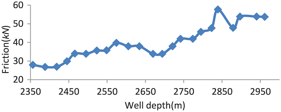
As the length of the horizontal section increases, the friction increases gradually in Shaxi Temple Formation.
Influence of rotation speed on friction
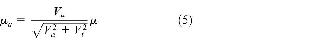
In the rotary drilling process of the horizontal well, there is a circumferential rotational friction (increased torque) in addition to the axial friction, and then the friction is decomposed into21,22

where Fa and Ft are expressed as
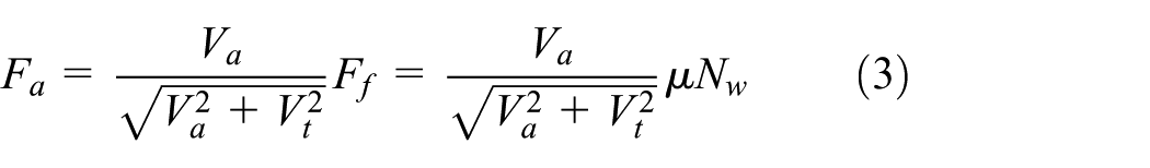

The components of friction coefficient are expressed as
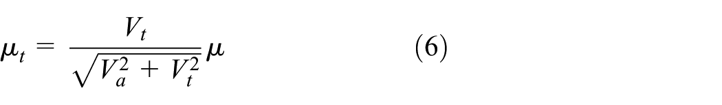
The friction is expressed as


The circumferential speed of the drill string is expressed as

In formula (9),
According to the above formulas, it can be seen that the friction is influenced by the rotational speed.
In addition, when a rigid object (drill string) is contacted with a viscous object (borehole wall), its viscous force (which acts as torque and friction in the borehole) is related to the static time. Meanwhile, the frequency of the relative displacement or the relative rotation between two objects has an effect on viscous force. In drilling, the viscous force occurs between the drill string and the borehole wall. The greater viscous force results in the greater torque on the drill string. However, if the drill string rotates faster, the relative rotational frequency with the borehole wall increases, the viscous force decreases, and the torque decreases. The viscous drill pipe sticking has resulted from the high viscous force. Therefore, during composite drilling with kickover tools, appropriately increasing the rotation speed could reduce the possibility of drill string sticking.
Influence of borehole trajectory on friction
Usually, a wellbore trajectory curve that reaches the target spot from the kickoff point and has the smaller friction is designed prior to drilling, as the well trajectory directly affects the friction and torque. Due to uncertainty of oil and gas exploration and development, the target spots are always adjusted and the control points in the horizontal section are added, which causes large undulation of borehole deviation and “W” shape of the horizontal section, resulting in excessive friction during drilling and affecting tripping in of casing. As shown in Figure 2, Well Shifang HF34-2 has the “W”-shaped trajectory and the locally large dogleg angle (the dogleg angle is 37.86°/100 m at the depth of 924.05 m, and over 30°/100 m at some points). After the well depth reached 1820 m (281 m into the horizontal section), severe torque and drag (4.5 kN) occurred after sliding drilling, the footage increased only when the bit pressure increased to 220 kN, and the drilling time was 60 min/m. As the well depth increased, the friction (6 kN) became more serious. When the well depth reached 2013.50 m, the drilling time of sliding drilling reached 70 min/m or more, and frequent tripping operation of the drill string is required. It is difficult to make up a joint, and tripping out the drill string needs borehole redressing. The torque is large during composite drilling.

Schematic of the “W”-shaped trajectory of the horizontal section of Well HF34-2.
Influence of drilling fluid density on friction
The high torque and drag always occurs during drilling horizontal wells in high-pressure tight reservoirs in Sichuan. One reason is the high drilling fluid density. For example, the formation pressure gradient of the fifth member of the Xujiahe Formation where the X605HF well is located is 1.70–2.0 MPa/100 m. In order to study the effect of drilling fluid density on the friction in high-pressure tight reservoirs, the frictions resulting from two drilling fluid densities in Well X605HF are compared. The friction along the well depth during drilling is shown in Figures 3 and 4. The friction resulting from the 2.1 g/cm3 drilling fluid is significantly higher than that resulting from the 1.4 g/cm3 drilling fluid. The reason is that increasing the drilling fluid density requires a higher solid content, which increases the filter cake thickness and the friction coefficient of the filter cake, resulting in viscous drill string sticking. The high drilling fluid density causes the high liquid column pressure, and the greater friction force and torque act on drilling tools which rotate in the borehole. Moreover, the chip hold effect occurs in the bottom hole, which causes repeated cutting of the formation, and the cuttings cannot be quickly run out of the bottom hole, which results in the cutting bed, thus increasing the friction and torque.

Comparison of friction during tripping in between two drill fluid densities.

Comparison of friction during tripping out between two drill fluid densities.
Investigation of the friction reduction tool
With the development and application of horizontal well drilling technology,15,16 the appropriate supporting tools should be further designed as soon as possible to meet the new technological requirements. Hence, a new tool for reducing torque and drag in horizontal well drilling has been developed in this study.
Design of the friction reduction tool
The structure of the friction reduction tool is shown in Figure 5. 42CrMo is used as the base material for the tool body. The primary technical parameters of the tool are the main spindle diameter of 165 mm, maximum working diameter of 205 mm, total length of 1250 mm, and the proposed borehole size of Ф215.9–Ф238.13 mm. Several departments of the friction reduction tool contain the main spindle, clearance adjustment rings, replaceable thrust rings, gyro wheels, and combination antifriction races. API threads are processed at both ends of the tool to connect with drill pipes while drilling. Combination antifriction race is of two symmetrical sections arranged with gyro wheels. During rotation, disturbance is produced by the specially designed upper and lower spiral diversion channels to the drilling fluid. Computational fluid dynamics (CFD) simulation results 14 have shown that the channels can help reduce rock debris accumulation and increase borehole cleaning efficiency in curved and horizontal wells. To make up and disconnect conveniently, elevator grooves are designed at the top and bottom of the tool.

Structure of the designed friction reduction tool.
The tool can effectively reduce the axial friction and circumferential torque in the drilling process. According to the antifriction principle of the tool, the designed outer diameter of the antifriction tool is larger than that of the drill pipe tool joint. As the drill pipe moves forward, the gyro wheels contact with the well wall and roll forward, which can transform sliding friction into rolling friction and therefore reduce the axial friction (shown in Figure 6). During the rotary drilling process, the main spindle rotates with the drill pipe, while the combination antifriction race contacts the well wall and does not rotate (its working principle is similar to that of the sliding bearing). Diameter of the main spindle is smaller than that of the drill pipe, and thus the rotation radius of the tool is reduced. In addition, the designed friction coefficient between the main spindle and the combination antifriction race is smaller. So axial friction and circumferential torque can be reduced effectively by the antifriction tool during drilling.
Cross section of the tool in the wellbore.
Field experiment
The designed tool needs to undergo a lot of tests and improvements from theoretical research to field application in oil industry. One of the authors has analyzed the laboratory experimental results of the tool. 14 Laboratory tests showed that (1) the average compressive force decreases from 730 to 410 N after installing the tool, a 44% decrease; (2) the average tensile force decreases from 640 to 370 N after installing the tool, a 42% decrease; and (3) the average torque decreases from 270 to 100 N m after installing the tool, a 63% decrease. However, the premise of realizing its function is to ensure that the tool has enough reliability.
The XP21-4 well is a directional well in Sichuan Basin of China. According to the wellbore trajectory parameter, the casing program is shown in Figure 7. The experiment for the antifriction tool was carried out in the second opening (from 270 to 1306 m).

Casing program of the XP21-4 well.
In order to test the reliability and function of the antifriction tool, it was connected with the drill pipe for second opening drilling. The total drilling time (130 h), fatigue life (3 × 10⁵ cycles), and other results are obtained after experiment. By observation and flaw detection (Figure 8), the following conclusions were shown: no crack is produced, the structure design of the tool is reasonable, and the mechanical properties of the material meet the requirements. However, some mud balling phenomenon was observed close to gyro wheels (Figure 9). According to similar design of other downhole tools, it is necessary to set the inclined plane and further chamfer treatment close to gyro wheels to reduce mud balling.

Ultrasound detection report of the antifriction tool after field experiment.

Friction reduction tool after downhole testing.
Drag and torque were recorded in the drilling in and trip operations of the directional section, as shown in Figures 10–12. According to the logging results, the bit pressure is 4–6 t and the friction is 3–6 t in the well section of 756–927 m. The bit pressure is 6–8 t and the friction is 9–12 t in the well section of 1080–1306 m. The friction is 11–13 t in trip out from 1295 to 991 m. Through comparison, the drilling friction of XP21-4 is approximately the same as that of adjacent wells in the same well section, which indicates that the single friction reduction tool cannot play a substantial role in reducing the friction. According to relevant technology and experience, 22 it is suggested that a certain number of equispaced tools should be placed at the curved interval of the well to achieve the function of reducing friction.

Friction in the well section of 756–927 m (WOB: 4–6 t).

Friction in the well section of 1080–1306 m (WOB: 6–8 t).

Friction in trip out from 1295 to 991 m.
The mathematical model of tool spacing
According to the test, the single friction reduction tool cannot significantly reduce the downhole friction (it does not show on the driller’s gauge). A certain number of friction reduction tools are needed to be placed in the drill string to maximize the function of tools. Therefore, the mathematical model of the spacing of the friction reduction tools needs to be established to provide technical support for studying the torque and drag in horizontal well drilling.23–27
During drilling, the tools are mainly placed in the curved interval of the well. It is always assumed that (1) the deformation of the two adjacent tools is approximately equal; (2) the drill string is a uniform equal section; and (3) the borehole is an equal curvature section within the vertical plane.
Two adjacent drill pipe sections ab and bc in the middle of the above borehole are analyzed (Figure 13). The friction reduction tools are placed at a, b, and c, respectively. The moment balance equation is defined for the force model, and then

where

Schematic of the force on the friction reduction tools in the inclined section.
By substituting formula (10) into the force–deformation formula obtained by the force test of the friction reduction tool, the deformation of the ab section is obtained. The force (Nb)–deformation (Sd) curve of the friction reduction tool is necessary for calculating the spacing of the friction reduction tools

It is assumed that, from the inclined section, drill string deflection occurs two times in the ab section (the initial curvature is approximately equal to the borehole curvature, and, moreover, affected by the gravity, axial force, and so on, the secondary deflection occurs in each drill pipe section. The compression deformation mainly occurs in the friction reduction tools), resulting in bending strain energy
The axial force of the rod end acts

The horizontal component of drill string effective gravity acts

The longitudinal component of drill string effective gravity acts

The bending moment of the rod end only acts during the first flexure

Total potential energy during bending is expressed as

According to the minimum potential energy principle and the geometric boundary conditions of deformation of the ab section drill string

By integral, we obtain

The maximum flexivity during secondary flexure is
The first term

where
When applying the friction reduction tool, the actual maximum eccentric distance of the ab section of the drill pipe in the curved section is S + 2a1. Thus, it is necessary to control S + 2a1 less than the permissible eccentricity

Equation (22) is solved to obtain the spacing
It should be noticed that the above analysis is based on the increased deviation, and equation (22) is only applicable in calculating the spacing of friction tools of the build-up deviation section. For the decreasing deviation section, R is converted to –R and βab is converted to –βab to calculate the spacing of tools.
Conclusion
Factors affecting friction during horizontal well drilling are analyzed, and a new friction reduction tool is developed for horizontal wells. The structure, material, working principle, and characteristics of the tool are described.
The lab test results show that the average compressive force has a 44% decrease, the average tensile force has a 42% decrease, and the average torque has a 63% decrease with use of the tool. The field test proves that the tool is safe and reliable and has the long life in the downhole conditions.
The mathematical model of calculating the spacing of the friction reduction tools is established, which provides technical support for investigating the torque and drag in horizontal well drilling.
Footnotes
Handling Editor: Han Zhang
Declaration of conflicting interests
The author(s) declared no potential conflicts of interest with respect to the research, authorship, and/or publication of this article.
Funding
The author(s) disclosed receipt of the following financial support for the research, authorship, and/or publication of this article: The authors are grateful to the support from the National Natural Science Foundation of China (No. 51574198).