
Abstract
Horizontal well is one of the important methods of unconventional oil and gas resource development. As increasing length of horizontal section, there is a serious problem that axial force cannot transfer to bit. The drilling field needs a low-friction and low-cost drag reduction tool. This article summarized existing technologies of drag reduction in the horizontal and inclined well and proposes an integrated design of torque clutch. Detailed design of tool sub-systems is introduced. The tool includes three sub-systems: clutch, hydraulic system, and monitoring system. The clutch is consisted of multiple clutch units mounted in a parallel arrangement. Power of hydraulic control system adopts difference in pressure between inside and outside of drill pipes. It can efficiently reduce power consumption. The design function and minimum working pressure are validated and obtained by indoor test. According to theoretical calculation, reasonable distance from tool to bit can be obtained for an actual drilled well. During directional drilling mode, the tool can reduce more than 30% axial drag of drill string according to theoretical calculation. The tool can effectively improve the capacity of transfer weight to bit and overcome the excessive drag in horizontal drilling. No similar tools are reported in the current field.
Keywords
Introduction
An important issue in drilling engineering relates to friction between the drill string and the wellbore.1–4 Excess friction is encountered in a long horizontal well that uses sliding drilling modes. 5 Additional drag and torque result in low rates of penetration (ROP), poor tool-face control, and prevent the transfer of weight to the drill bit. There are some drag reduction technologies that have been widely used in the field. The tools fall into two categories, mechanical method and chemical method. 6 The chemical technologies mainly are lubricants additive in the drilling mud.7,8 The mechanical drag reduction methods are more suitable than chemical method due to low-cost and environment friendly. The mechanical technologies include hydraulic oscillator tool,9–13 Slider Drilling Technology,14–20 roller centralizer,21–24 and so on.
The present study of drag reduction mechanism focused on down-hole vibration tools. The vibration mode includes axial, torsional, and lateral. There are three kinds of oscillation tool that classified by vibration mode and widely used in the fields. They are National Oilwell Varco (NOV) Hydraulic Oscillation System, Three-Dimensional Hydraulic Oscillation System, and Radial Hydraulic Oscillator. The numerous research focus on axial oscillation tools. However, there still are some disadvantages of the current vibrational drag reduction method.25,26 The mainly problem is poor performance of drag reduction. Because activated state caused by vibration tools is limited in a small range of drilling string.27,28 It cannot effectively reduce the friction of entire drill string during slider drilling mode.
The Slider Drilling Technology is another practical drag reduction method used in the fields for more than a decade. The system works by rotating the top of the drill string, so the upper part of the drill string always experiences tangential motion. The system maintains the drill string friction in the dynamics mode and significantly reduces axial friction.19,20 However, the direction of rotary is not one-way. It changed the direction periodically to prevent instability of tool-face orientation.20–23 Therefore, there is maximum depth to which a particular applied surface torque can twist the drill string. This depth is determined by a typical torque and drag program.14–16 The actual maximum depth is influenced by the surface maximum clockwise and counterclockwise torque. 17
There is another type of mechanical drag reduction tool, roller centralizer. The representative tool is Weatherford LoTORQ. The rolling friction factor between roller and axle is lower than sliding friction factor between drill string and wellbore. Therefore, roller-based tool can significant reduce torque and drag of string in the down-hole. However, there are the same disadvantages, limited scope of influence. The roller centralizers also increase stiffness of drill string and problem of tripping. 29
This article proposes a novel drag reduction tool for extended reach wells and horizontal wells. The article is structured as follows. Section “Novel directional drilling method and tool” introduces the structure of torque clutch drilling tool, including working principle, detailed design of sub-systems of tool. Section “The simulation parameters” introduces the simulation actual drilled well and make-up of string adopting to analyze tool performance of drag reduction. Section “Tool usage” introduces usage of torque clutch drilling tool, including surface control process and installation position. Section “Indoor test” introduces validation of design function of tool by indoor test. Section “Evaluation of tool drag reduction performance” introduces evaluation of tool drag reduction performance using modified drag-torque model. The drill string transfer capacity of weight on bit (WOB) is also analyzed with torque clutch drill tool in this section.
Novel directional drilling method and tool
This section introduces a novel drilling method. The method uses a new tool called torque clutch drill tool. Drag reduction mechanism of the tool is completely different from the past drag reduction tools. Therefore, structure of tool is designed specially.
Novel drilling method and drag reduction mechanism of tool
The torque clutch drill tool is used with position displacement motor (DPM) and measurement while drilling (MWD) system. The tool is installed near bit. Below the tool, the drill string is usually drill collar (DC). These DCs are connected with non-magnetic DCs and positive displacement motor with bent-house. Up the tool, drill string is usually drill pipes (DP) or heavy-weight drilling pipe (HWDP), as presented in Figure 1.

Novel drilling method and drag reduction mechanism of torque clutch of drill tool.
The tool can mesh the teeth when tool-face does not need to be maintained. It can implement compound drilling. The torque produced by surface rig can be transfered to bottom hole assemble and bit through the tool. When the tool-face of bottom hole assembly (BHA) needs to be changed, the teeth of tool can be apart. The torque of surface cannot transfer to BHA and bit. The tool-face maintains constant no matter how fast rotary table rotates. Reactive torque of bit is eliminated by the friction of DCs that below the tool. Therefore, directional drilling is implemented.
During compound drilling mode, the whole drill string is rotating. The axial friction, also called drag, is extremely low. There is usually no problem of WOB transfer. The excessive drag generally occur during slider drilling mode without rotating the drill string. Therefore, using the torque clutch drilling tool, the axial friction of drill string of upper tool can significantly reduce during directional drilling mode. The drag is mainly generated by DCs and BHA that below tool. This drag is extremely low compared by entire drill string with traditional directional drilling method. Therefore, the torque clutch drilling tool can efficiently reduce drag and keep constant tool-face during directional drilling mode.
Detailed structure of tool
According to the work mechanism of torque clutch aforementioned, the detailed mechanical structure of tool is designed. The torque clutch drilling tool consists of three parts. These are control system, hydraulic system, and clutch, as presented in Figure 2. The control system can analyze received surface signal and send control information. The hydraulic system receives control instruction and pushes/pulls the clutch. The clutch can transfer or separate torque controlled by hydraulic system.

Sub-systems of torque clutch drill tool.
Clutch
The clutch is an actuator of tool. It can transfer or separate the torque from the upper parts of tool to low parts. The type of clutch adopts mesh gear. However, the design of out diameter of clutch is constrained by the wellbore. The capacity of mesh gear is less than operation torque of bit. In order to solve this problem, this article adopts parallel structure of mesh gear to transfer great torque. In the scheme, there are eight pairs of parallel mesh gears.
As presented in Figure 3, the clutch consists of driving shaft, internal gears, external gears, upper shell, and lower shell. The upper shell is connected with driving shaft through spline. The driving shaft includes piston and external spline. The eight internal gears are installed and fixed on the spline of driving shaft. The eight external gears are also installed and fixed in the spline of shell. The driving shaft can move up and down along axis of tool with eight internal gears together through spline. When driving shaft moves down, the internal gears on the driving shaft will mesh into external gears installed in the shell. When driving shaft moves up, the internal gears on the driving shaft will separate from external gears in the shell. The external gears are connected with lower shell through spline too, as presented in Figure 4.
The clutch.
The structure of mesh gears.
There is a piston on the end of driving shaft. As presented in Figure 5, the piston can push or pull the driving shaft under fluid pressure of hydraulic system. When upper chamber of piston is higher pressure, piston moves down with internal gears. The internal gears are meshed with external gears. The torque can be transfered from driving shaft to lower shell thought the internal and external gears. When upper chamber of piston is lower pressure and lower chamber of piston is higher pressure, driving shaft moves up with internal gears. The internal gears are separated from external gears in the lower shell. The torque cannot transfer from driving shaft to lower shell. The shaft will be idle with internal shaft. Therefore, the clutch can execute function that transfer or separate torque from upper shell to lower shell by controlling fluid pressure of piston chamber.
The piston stroke of clutch.
Hydraulic system
The hydraulic system is an important part of control system. The hydraulic system can provide difference in pressure between two opposing surfaces of piston. The hydraulic system also needs power to generate the differential pressure. The power may come from battery, like other down-hole tool. However, it needs a large number of batteries to feed the hydraulic system. The high-cost and impossible volumes of batteries will obstacle the promotion of tool. Therefore, this article adopts the difference in pressure between internal and external of tool as power of hydraulic system when drilling fluid circulation in the wellbore and circulating opening.
The drilling mud can be used as hydraulic fluid. However, solid phase particles in the drilling fluid will ruin hydraulic system. The isolation part of hydraulic system is designed to protect hydraulic from contamination of drilling fluid, as presented in Figure 6. Design minimum working pressure difference is equal to 2 MPa. The difference in pressure between internal and external of tool can be controlled by two two-position three way solenoid valves, as presented in Figure 14. Controlling two two-position three-way solenoid valves, the higher pressure will push the piston in the driving shaft down or pull the piston up. The gear meshing or separating can be controlled.

Two mode of hydraulic system.
Monitoring system
Monitoring system is a sub-system, which received signal sent from surface and control two solenoid valves. The system is continually detecting pressure of internal tool and record last several signals. The command of surface can be explained by comparing changes of record signals. The pressure signal produced by pumping and termination of pumping on preset time series. The working principle is the same with control mechanism of tapered stabilizer. According to the signal, monitoring system implement solenoid valves for pressure control. Furthermore, it controls the fluid pressure to push or pull the piston, and then the clutch is meshed or separated. The monitoring system is consisted of power module, solenoid control module, pressure signal module, and so on, as presented in Figure 7.

Diagram and photo of circuit.
The simulation parameters
Well profile
To illustration the tool usage and evaluation of tool drag reduction, an actual drilled well is presented in this section. The detailed parameters are listed in the following. The wellbore configuration is presented in Table 1.
Wellbore configuration.
Diagrammatic of designed wellbore configuration is shown in Figure 8. The horizontal distance from point A to point B is 1500 m. The horizontal well section is slightly upward. The long horizontal well section may be resulted in excess drag. There may be a problem that WOB cannot transfer to the bit.

Diagrammatic of designed wellbore configuration.
The surveying data of inclination and azimuth are presented in Figure 9. These are two local maximum inclinations in the horizontal well section.
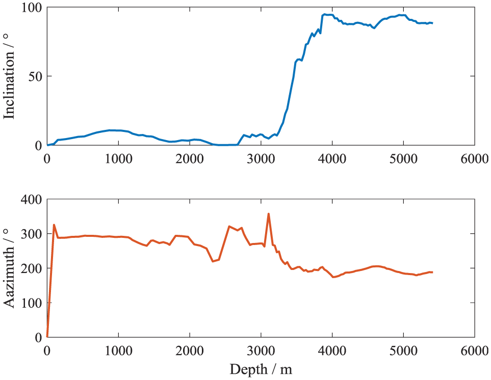
Survey data of wellbore trajectory.
Combination of drill tool
The torque clutch drill tool need to work with a specific combination of drill tool. They are consisted of torque clutch drill tool, DC, non-magnetic DC, and positive displacement motor with bent-house, MWD, and bit.
It this article, these are two combination of drill tool that simulated. The No. 1 is bit + positive displacement motor + non-magnetic DC + DC + torque clutch drilling tool + drill pipe. The No. 2 is bit + positive displacement motor + non-magnetic DC + drill pipe. The No. 2 combination of drill tool is widely used in the shale gas field.
Tool usage
The torque clutch drill tool or similar tool is not reported in the industry and academia up to now. There are especial method of tool application in the different drilling situation. However, these methods of application do not affect existing drilling equipment in the field. The usage of torque drill tool includes two parts. The first part is surface control process. The second part is the installation position of tool
Surface control process
Adopting the slider drilling method with MWD and steerable mud motor, it needs to switch between slide drilling mode and compound drilling mode. During directional drilling mode, it needs torque clutch drilling tool to be separated. During the compound drilling mode, it needs that tool is meshed. Therefore, tool should receive control command of surface and change the working mode of tool.
At present, there are many telemetry technologies used in the drilling engineering, for example, mud pulse communication, acoustic communication, and electromagnetic communication. These technologies have disadvantages of low reliability and high cost. They are not suit for torque clutch drill tool. The tool only has two working modes. Therefore, this article adopted turn-on pump and turn-off pump method to send command to tool.
The process of turn-on and turn-off pump will generate pressure changes inside and outside of the tool. A method of pressure measurement software is designed. If three times of high-pressure and low-pressure signals appeared alternately in the specified time, the signal is effective. If the alternately high- and low-pressure signal is less or more than three times in the specified time, it is an invalid signal. If the times of alternately signal are equal to three, however not detected in the specified time, it also is an invalid signal.
The surface control signal can send to tool, the tool conditions should be known by the surface. It needs a method to distinguish whether the tool is in meshed status and separated status. There are several methods to obtain tool status according to the design.
First method is rotating rotary table, then analyzing whether the tool-face measured by MWD is changed. The second method is that rotating rotary table and record stable surface torque. Operation of turn-on and turn-off pump can switch tool status. Rotating rotary table again and record surface torque when it is in stability. If first record torque is less than second, the tool is meshed. If first record torque is greater than the second, the tool is departed. The process is presented in Figure 10.

Control and feedback process.
The closed-loop control is established. The process of switch tool status is presented in Figure 11.

The usage of torque clutch drill tool.
Installation position
The installation position of tool in the drill string is determined by two factors. First factor is the difference in pressure between internal and external of tool when drilling fluid is circulating, as presented in Figure 10. The second influence factor is friction torque of drill string below tool that overcome reactive torque of bit during breaking rock.
Stability of tool-face orientation during directional drilling
The factors that influence tool-face stability are analyzed in this section. These factors include reactive torque of bit, density of drilling fluid, and DC specifications. The simulation parameters are presented in the previous section, which include well profile and combination of drill tools.
The stability of tool-face depends on friction torque of drill string below the tool. Therefore, longer drill string below the tool is benefit for stability of tool-face during directional drilling. Increasing length of drill string below the tool will enhance stability of tool-face orientation. Meanwhile, it exist a minimum length of drill string below the tool that can just be equal to reactive torque of bit. The minimum length of drill string is an importance parameter for the tool usage.
The well depth of simulation is between 4200 and 5300 m. The reactive torque of bit is 3000, 3500, and 4000 N m, respectively, as presented in Figure 12. The minimum length of drill string below the tool is varied at different well depths. Due to adopt real well trajectory and other determined factor, the minimum lengths are mainly affected by borehole inclination and curvature. However, the variation trends of the minimum length of drill string below the tool are roughly consistence with wellbore inclination.

The minimum length of drilling string below the tool influenced by different reactive bit torques.
According to simulation results, the density of drilling fluid is less influence in the minimum length of drill string below tool than reactive torque of bit. There are few distinctions in the curves at the same well depths, as presented in Figure 12. The greater densities of drilling fluid generate greater buoyancy for the drill string. The greater buoyancy reduces normal force between drill string and wellbore. It also reduces friction to overcome reactive torque of bit. However, the density of mud is not dominant factor for the minimum length of drilling string below the tool (Figure 13).

The minimum length of drilling string below the tool influenced by different densities of mud.
According to the above analysis, the DCs are chosen as drilling string below the tool. These are different weights and outer diameters of different DC specifications. The thicker of DC is heavier than the thinner. The thicker DC produce greater normal force and friction torque than the thinner. Therefore, the thicker of DC can make tool-face orientation more stable. The minimum length of 178 mm DC is shorter than 165 mm DC according to simulation results, as presented in Figure 14.

The minimum length of drilling string below the tool influenced by different drill collar specifications.
For the simulation well and combination of drill tool listed in section “The simulation parameters,” the minimum length that is equal to 300 m can satisfy requirements of stability of tool-face orientation. Using aforementioned computational model in Appendix 1, the tool installation position can be obtained according to the designed well trajectory and combination of drill tool.
Efficient differential pressure
It is important that there is efficient differential pressure between internal and external tool when drilling fluid is circulating. The tool usually is used in the horizontal well and deviated well. The drill string in the horizontal and deviated well is eccentric, as presented in Figure 15. The pressure lost calculation must be considered the factor of eccentric. Using hydraulic model of wellbore, the differential pressure is calculated, as presented in Figure 16.

The difference in pressure consisted of several kinds of pressure loss.

The difference in pressure between internal and external of tool when WOB is equal to 6t.
The distances from torque clutch drilling tool to bit are 200, 300, and 400 m, respectively. The differential pressure between internal and external of tool satisfy the tool requirements (2MPa) with eccentric and concentric drill string. Considering stability of tool-face, distance from tool to bit is set to be 300 m is reasonable according to simulation results for the calculation well.
Indoor test
Test equipment and scheme
To validate function of tool on the ground surface, an indoor test is conducted. The tool requires fluid dynamic pressure for power. The fluid loop can produce efficient pressure for tool indoor. Therefore, we adopt test bench of down-hole tool to validate the function of torque clutch. The test bench of down-hole tool is consisted of water tank, pump, and console cabinet and fluid loop, as presented in Figure 17. The performance parameters of pump are listed in Table 2. The assembled torque clutch drill tool is presented in Figure 18.

The test bench of down-hole tool.
Performance parameter of pump.


Assembled torque clutch drill tool.
Functional verification
When tool is fixed in the test bench, the outer pressure of tool is atmospheric pressure. The inner pressure of tool is flowing pressure. It exists difference in pressure between inside and outside of tool. Due to shortage of fluid loop, the flowing pressure is less than 2 MPa, which is one of important design parameters. It is not enough to make tool work normally.
To solve this problem, a plug is designed. It installed in the end of tool. Closed space is formed with the plug and water pipe, the inside pressure can be built and controlled by overflow valve of pump. The effective pressure between inside and outside of tool make tool work.
The pressure built by the pump propagates to inside of tool through the water pipe. There is no flowing fluid; the pressure is static pressure. The fastener of test bench fixes the parts of tool above bearing. The parts below bearing rotate freely if clutch is not meshed, as presented in Figure 19.
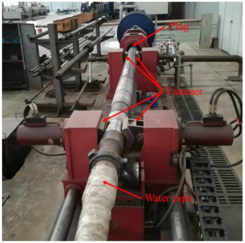
Torque clutch in the test bench.
Increasing pressure from 0 to 5MPa with step of 0.5MPa. Twisting the pipe wrench when pressure is stable, then observing tool whether it can be rotated. If pipe below the bearing can be rotated, it illustrates that the clutch is separated. If pipe below the bearing cannot be rotated, the clutch is meshed. The process of increasing pressure of pump is stopped until tool is meshed, as presented in Figure 20.

Using pipe wrench to verify tool whether to mesh.
When the pressure of pump is 2.02 MPa, the clutch is meshed. Keeping the stability of pump pressure, controlling the pressure by the solenoid valve, the tool is separated again, as presented in Figure 21. It can be determined by rotating below parts of tool freely. The above procedures are repeated several times, the minimum working pressure is reliable, which is about 2 MPa. Therefore, the working pressure of torque clutch is 2.02 MPa that can make tool meshed and separated by controlling solenoid valve reliably. The value of pressure is approximate to the design value and satisfied requirement of tool. The function of tool is validated by the indoor test. The tool can mesh and separate under control.

Pressure monitor plane.
Evaluation of tool drag reduction performance
The drag reduction performance can be obtained by the computation model described in Appendix 1. This section focuses on the drag reduction performance using modified drag and torque model and capacity improvement of WOB transfer using dynamic drag and torque model.
Performance of drag reduction
The calculation parameters are listed in section “The simulation parameters”. The distributed friction of two combinations of drill tool is presented in Figure 22 in slide drilling mode. The red curve is No. 1 combination of drill tool with torque clutch drilling tool. The blue curve is No. 2 combination of drill tool that widely used in the directional drilling of horizontal well at present. According the simulation results, the torque clutch drill tool can remarkably reduce distributed friction of whole drill string especially in the horizontal well section.

Distributed friction of different combinations of drill tool.
The distributed friction with different ROPs are simulated, results are presented in Figure 23. The distributed frictions below the tool are the same with different ROPs. Up the tool, the greater ROP results in greater distributed friction.
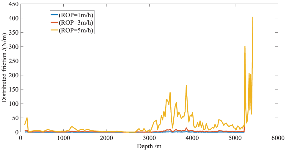
Distributed friction of different ROPs.
The total frictions of whole drill string are presented in Figure 24. It also indicates that torque clutch drill tool can efficiently reduce total friction of drill string during directional drilling model. Amplitudes of drag reduction are more than 70%. Figure 24 also indicates that the total friction of drill string is positive correlation with the ROP.

Total friction of different kinds of make-up of string.
Improvement of WOB transfer
The lower axial friction of drill string can increase capacity of WOB transfer. Using dynamic drag and torque model presented in Appendix 1, it can analyze the improvement of WOB transfer with torque clutch drilling tool.
The distance from tool to bit is 300 m. The drilling strings below the tool are DCs. The rock-bit interactive model is adopted for WOB calculation, which described in Appendix 1. The speeds of rotary table are 1–59 r/min with 2 r/min as step. According to simulation results, which are presented in Figures 25–28, the WOBs rapidly increase over simulation time. Then they become steady-state fluctuation. The WOB is calculated when ROP is 1, 5, 10, and 15 m/h. The rotate speed of rotary table ranges from 1 to 59 r/min with 2 r/min as step.
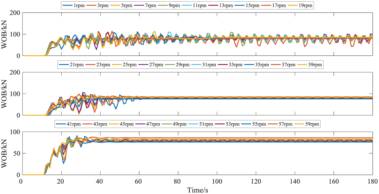
Changes of average WOB when ROP = 1 m/h.
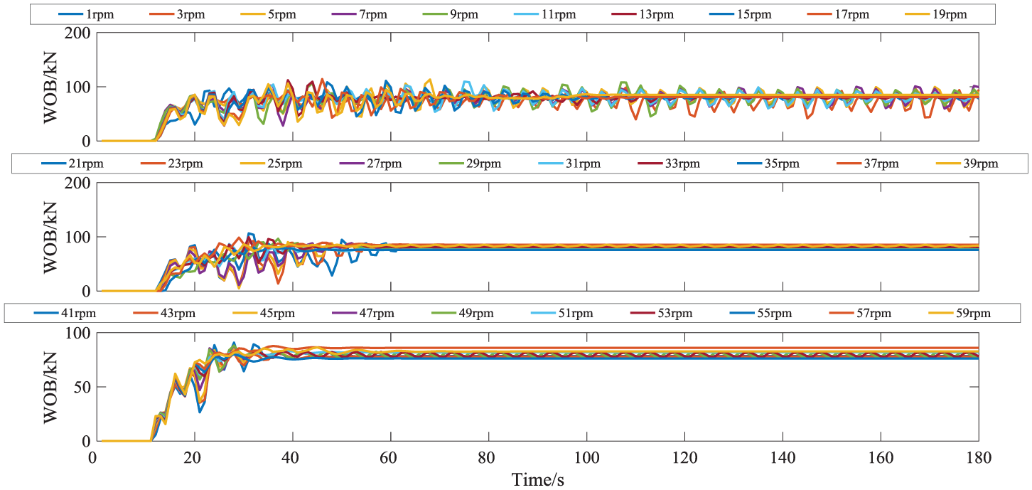
Changes of average WOB when ROP = 5 m/h.

Changes of average WOB when ROP = 10 m/h.

Changes of average WOB when ROP = 15 m/h.
The average of steady fluctuation WOB is approximate linear relation with speed of rotary table using torque clutch drill tool. Without torque clutch drill tool, the WOB is equal to zero in the range of simulation parameters, as presented in Figure 29. In general, the less ROP leads to the greater average WOB. The torque clutch drilling tool can remarkably improve the capacity of WOB transfer.
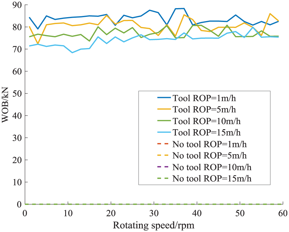
The average WOBs with different ROPs.
Conclusion
This article proposes a novel drilling method. The tool of new drilling method is called torque clutch drill tool. The tool can keep rotary table rotating during directional drilling model with bent-house positive displacement motor and MWD. It can efficiently reduce axial friction of drill string during slider drilling model.
The structure of novel is introduced in the paper, which consist of clutch, hydraulic system, and monitor system. The indoor test is conducted with test bench of down-hole tool. The results of indoor test validated the design objective of tool. The usage of torque clutch drill tool is also described. It involves two aspects. First one is stability of tool-face orientation during directional drilling model. Second one is whether difference in pressure is sufficient for the tool.
Using the drag and torque model and circulation pressure loss model, the reasonable position of tool is determined that satisfy aforementioned two aspects. Based on the dynamic drag and torque model and simulation parameters, improvement of WOB transfer ability is validated with torque clutch drilling tool. Results of simulation suggest that the novel tool can remarkable reduce drag and improve capacity of WOB transfer.
Footnotes
Appendix 1
Bingham fluid rheological equation is presented as follows
where τ is shear stress, γ is shear rate, μ∞ is plastic viscosity and τ0 is yield value.
Reynolds number of Bingham fluid in the pipe 30
if Re < Rec flow state is laminar flow, otherwise is turbulent flow.
Laminar friction coefficient 31
Turbulent friction coefficient 31
Reynolds number of annular flow uses dao–dai, instead di. Pressure drop gradient formula is presented as follows 32
where p is pressure of internal of drill string or annular, s is depth of wellbore, ρm is density of drill fluid, g is acceleration of gravity, α is inclination, dh is equivalent hydraulic diameter, dao is outer diameter of annular, dai is inter diameter of annular, and vm is average velocity of drilling fluid.
Annulus pressure at surface is equal to 0, the pressure distribution of annulus can be obtained by the boundary condition and pressure drop gradient formula.
Calculation formula of bit pressure drop is presented as follows
where ΔPb is bit pressure drop, Q is volumetric displacement, ρm is density of drilling fluid, d1, d2, d3 are nozzle diameters of bit.
Drill string rotation factor is changed as Taylor number and Reynolds number; the Taylor number is described as follows33,34
when Ta < 46
when 46 ≤ Ta ≤ 830, drill string rotation factor for characteristic Reynolds number is presented as follows
where Ft is drill string rotation factor, Ft1 is No. 1 drill string rotation factor, Ft2 is No. 2 drill string rotation factor, Ftmax is maximum of drill string rotation factor, ω is angular velocity of rotation, k is consistency coefficient, Dp is outer diameter of drill pipe, and DH is diameter of wellbore
For eccentric factor 35
eccentric factor is maximum in the horizontal well section
where dw is diameter of wellbore, dpo is diameter of drill pipe, emax is max eccentric factor, and
Calculation method of eccentric factor based on the Herschel–Bulkley model is described as follows
For Rec
For Rec2
For Remax
For Rlam
For Rtur
Calculation of eccentric factor
where n is rheological index, Rec, Rec1, Rec2 are critical Reynolds number, Relam is laminar eccentric factor, Retur is turbulent eccentric factor, Dp is diameter of drill pipe, and Dh is diameter of wellbore.
The pressure loss of positive displacement motor 36
where ΔP is pressure loss of positive displacement motor, P0 is pressure loss of positive displacement motor of maximum volumetric displacement, Q is volumetric displacement, Q0 is maximum volumetric displacement, W is WOB, and a, b, f, k are structure coefficients
where P1 is working pressure of positive displacement motor, Pmax is maximum pressure loss of positive displacement motor, T1 is working torque of positive displacement motor, Tmax is maximum working torque of positive displacement motor, W1 is working WOB, and Wmax is maximum allowable WOB.
The drag and torque model have been widely used in the about 30 years.37,38 It has been made great achievements. The basic assumption of the model is that the axis of combination of drill tool is coincidence with the axis of wellbore.30,38,39 Figure 30 presents an element of drill string in the natural coordinate system. The forces and moments condition are also presented in Figure 31.
The equilibrium equation of force and moment is described as follows
where F is equivalent internal force considering inside and outside pressure of drill string, h is equivalent external force, m is external distribution moment, and s is depth of wellbore.
According to the differential geometry, the equilibrium equation of force and moment deduces to following equations
According to relationship between bending moment and curvature, the following equation can be obtained
where Mb is bending moment, E is modulus of elasticity, and I is moment of inertia.
Torsion is ignored, it can be deduced from the hypothesis following equation.
where Te is effective axial force of drill string, Qn is shear force of direction of principal normal, Qb is shear force of direction of bi-normal, Mb is internal bending moment of drill string, Mt is torque of drill string, k is borehole curvature, τ is borehole torsion, N is normal force between drill string and wellbore, Nn is normal force of principle normal direction, Nb is normal force of bi-normal direction, fλ is viscous resistance of drill string, qm is line weight of drill string in the drilling fluid, q is line weight of drill string in the air, ρi is fluid density of internal drill string, ρ0 is fluid density of external drill string, Ai is sectional area of internal drill string, A0 is sectional area of external drill string, μa is axial coefficient factor, μt is tangential coefficient factor.
However, the above formulas cannot describe the friction torque distribution of below the torque clutch drill tool during directional drilling mode. Analyzing the actual down-hole environment, there are two conditions. They are that driving torque on the top of drilling string is greater than friction torque and driving torque on the top of drilling string is less than friction torque.
For the first situation, the torque distribution computational process is follows.
M
t(s = si) =
Mt(s = si) =
The boundary condition is follows
For the second situation, the calculation of torque distribution is presented as follows.
The boundary condition is follows
where TOB is torque on bit, WOB is weight on bit, Ni is the normal force of ith element between drill sting and wellbore, μi is coefficient factor of ith element between drill string and wellbore, ri is outer radius of drill string, Mt is torque on the element, Mex is external torque on the element, and n is the number of element. The aforementioned equations can be solved by Newton iteration method.
To analyze WOB transfer capacity, the dynamic drag and torque model is established. The basic assumptions of this model are described as follows40,41: (1) The drill string is in elastic deformation. (2) The gap between drill string and wellbore is ignored; the axis of drill string is coincidence with axis of wellbore. (3) The drill string only have axial and circumferential freedom.
The drill string can discrete by a series of lumped mass, axial spring, and torsion spring, as presented in Figure 32.
According to the principle of Hamilton and basic assumption of model, equations of motion of single lumped mass can be deduced from basic equation of Hamilton 42
For the drill string system, the equation of system motion equation can be assembled by each equation of single lumped mass. The equation of system described as follows
The mass matrix of drill string system
The damp matrix of drill string system
The stiffness matrix of drill string system
where T is kinetic energy of drill string system, V is potential energy of drill string system, δWnc is virtual work done by the non-conservative forces on the system, mi is mass of ith element, Ii is moment of inertia of ith about the borehole axis, k i is stiffness of ith element, c i is damp of ith element, q i is displacecment of ith element, g is ravitational acceleration, H i is height of ith element.
The external force of single lumped mass is showed in Figure 33. The external forces include gravity, axial friction, friction torque, and normal force between drill strings and wellbore. In the axial direction, these are only gravity component, axial friction and pull force between each lumped mass. In the direction of rotation, these are friction torque, torque between each lumped mass.
The normal force between drill string and wellbore is important factor of friction computation. This force of single lumped mass is related to inclination and gravity of lumped mass. The formula of normal force is presented in Figure 33. The aforementioned equation can be solved by numerical method that is Newmark-β method.
The calculation of WOB is based on Hertz contact theory. The force that rock acted on bit can be described as follows43–46
where F is force that rock acted on bit, k is stiffness of rock, c is damp of rock, Δ is the depth that bit embedded into the tock, x is bit position, and s0 is position of bottom hole
where
where rb is diameter of bit, δc is cutting depth of per round, μ is friction coefficient, ξ is coefficient, TOB is torque on bit, and WOB is weight on bit
ROP is rate of penetration and ωd bit average speed
where c1c2 are coefficients and F0 is force loaded on the bit
where α, B, ν, γ are coefficients, and μ0 is friction coefficient.
Handling Editor: Jose Ramon Serrano
Authors note
Xingming Wang is also affiliated with State Key Laboratory of Oil and Gas Reservoir Geology and Exploitation, Southwest Petroleum University, Chengdu, China.
Declaration of conflicting interests
The author(s) declared no potential conflicts of interest with respect to the research, authorship, and/or publication of this article.
Funding
The author(s) disclosed receipt of the following financial support for the research, authorship, and/or publication of this article: This research was sponsored by the Sichuan Province Science & Technology Program (Grant No. 2015SZ0003) and the National Natural Science Foundation of China (Grant No. 51274171).