
Abstract
In this article, a new friction reduction tool is designed for drilling of horizontal wells, and its performance is investigated using computational fluid dynamics simulation technique, laboratory experiment, and field testing. According to flow field analysis, the spiral diversion channel has obvious disturbance effect on fluid, which can help cutting transport and reduce cutting bed accumulation. Tensile test is carried out and tensile resistance of the friction reduction tool is 90 ton. Shearing test is also conducted to examine the shear resistance capacity of the pins that support rollers. Under the lateral load of 20 MPa, large deformation of the pins is observed, but they are not broken. The function of friction and torque reduction is verified using experimental apparatus for drill string dynamics of horizontal well. Field testing is also completed in a real well. The accumulated operational time of the friction reduction tool is more than 130 h and its fatigue life reaches up to 3×10⁵ cycles. The simulations and experiments indicate the designed tool can effectively reduce friction and torque in horizontal wells. The work presented in this article can provide a technological basis and scientific reference for the development and application of friction reduction tool in horizontal wells.
Introduction
Horizontal well has been proved as an essential technique for effective exploitation of natural gas reservoirs. However, excessive torque and drag can seriously restrict the success of long horizontal drilling. The parameters included in the torque-and-drag equations are shown below.1–3 Drag is directly proportional to the normal force, coefficient of friction, and pipe movement (formula (1)).Torque is directly proportional to the normal force, coefficient of friction, radius of the object that is rotating, and tubular movement (formula (2)). Reducing any of the components in the equation will ultimately reduce the torque or drag


where
The main measures to reduce friction can be classified into four categories:4–8
Optimize well trajectory. Drag and torque can be different when different well trajectories are drilled for the same target. Therefore, friction can be reduced by optimizing well trajectory.
Optimize well structure and bottom hole assembly (BHA). Wellbore size, BHA, and casing program have great influence on drag and torque. Some scholars point out that drill string with smaller diameter and higher strength should be used under the premise of hole-cleaning and annulus flow back.
Optimize drilling fluid. Optimizing drilling fluid parameters and using effective lubricant can improve the quality of mud cake, and the lubricity of contact surface can also effectively reduce torque and drag. Appropriate fluid-dynamic parameters can improve cutting-carrying and friction-reduction abilities.
Use friction reduction tool. Various friction reduction tools are designed and manufactured, most of which are used at build-up section. The application of these friction reduction tools can effectively reduce drag and torque, extend horizontal length, and prevent serious accidents.
Based on the existing designs to reduce drag and torque,9–11 a new friction reduction tool is designed and manufactured for horizontal wells. This tool is mainly used in extended-reach wells, directional wells, and horizontal wells. Its effects have been verified to include reducing drag and torque, lightening wear of casing and tool joint, preventing differential pressure sticking, and improving penetration rate. In this article, the reliability and function of the tool are examined by computational fluid dynamics (CFD) simulation, laboratory experiment, and field testing.
Design of friction reduction tool
The designed friction reduction tool is shown in Figure 1. The material of tool body is mainly 42CrMo. The tool is composed of spindle, clearance adjustment rings, replaceable thrust rings, gyro wheels, and combination anti-friction races. Both ends of the tool have threads to connect with drill pipes. There are also elevator grooves on the tool to help make up and disconnect. The upper and lower spiral diversion channels have obvious disturbance effect on fluid flow as velocity of fluid is relatively high. This effect can improve cutting-carrying ability, reduce cutting-bed accumulation, and increase borehole cleaning efficiency in horizontal wells.

Structure of the designed friction reduction tool.
Drag and torque can be effectively reduced when using this tool. The maximum outer diameter of friction reduction tool is bigger than that of tool joint. When drill string slides in the wellbore, rollers will contact with wellbore (Figure 2), which can transform sliding friction into rolling friction and therefore reduce the friction. In rotary drilling process, friction reduction tool rotates with drill string while bearing housing does not rotate. Under this situation, rotation radius is reduced. In addition, the friction coefficient between the tool and bearing housing is smaller. So, torque of drill string can be effectively reduced when using the friction reduction tool. The primary technical parameters of the tool are as follows: tool body diameter of 165.1 mm, maximum working diameter of 204.5 mm, total length of 1230 mm, and proposed borehole size of Φ215.9–Φ238.13 mm.

Cross section of the tool in wellbore.
To ensure that the designed tool can reduce drag and torque safely and reliably, theoretical analysis and laboratory experiment must be carried out before field test and application. CFD simulation technique is carried out in this article to conduct the field analysis. Laboratory experiments including static-loading testing and functional testing are conducted. Then, field testing is also completed in a real well. The methods and achievements of this research can provide a technological basis and scientific reference for the development and application of friction reduction tool.
Flow field analysis
In order to study the disturbance effect of spiral diversion channels on fluid flow in drilling process, flow analysis is carried out. In addition, the influences of cutting-carrying ability and cutting-bed accumulation are also analyzed.
The flow field model is shown in Figure 3. In the simulation, friction reduction tool is placed at horizontal section and it rotates with drill string. Fluid–solid coupling computation is applied considering that the influence of solid on fluid flow is involved. The flow line of CFD model is shown in Figure 4. Figure 4(a) and (b) illustrates the conditions when the tool does not rotate and when it rotates, respectively.

Flow field model of the tool.
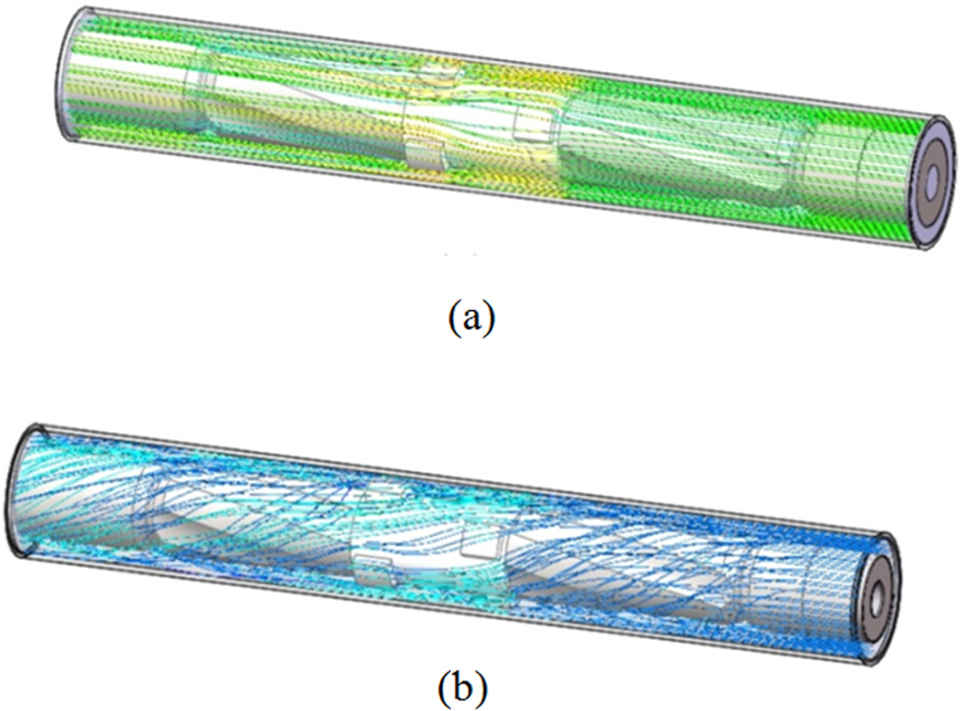
Flow line of CFD model: (a) non rotation and (b) rotation at 60 r/min.
In Figure 4(a), when the tool does not rotate, flow lines are approximately straight lines except for some turnings at bulges. In Figure 4(b), the rotary speed of the tool is 60 r/min. Fluid flows in a straight line at the inlet while the direction of flow line changes at spiral diversion channel. Flow line inclines to the direction of rotation.
The migration of cuttings of different size is also studied in the wellbore where the tool is located. Assuming cuttings are spherical, the diameter of cuttings is 0.3, 4, and 13 mm, respectively. The debris is quartz sandstone with a density of 2.8 g/cm3. Cuttings enter from the right side of the model with initial velocity of 0.04 m/s. The initial velocity of the fluid entering the model is 18 m/s in the same direction with debris.
It can be seen from Figure 5 that when diameter of cuttings is small (0.3 mm), the migration pattern of cutting particles is suspended and the maximum velocity of cuttings can reach 19.6 m/s. The cuttings move in a straight line, only when colliding with the protruding parts of the tool, the path is changed and some cuttings bounce back, and then continue to suspend forward driven by the fluid.

Migration of small-size cuttings (diameter of 0.3 mm).
If cutting size is middle (4 mm), the migration pattern of the cutting particles is no longer suspended, as shown in Figure 6. Cuttings enter from the right of the model and move forward, and then sink to the low side of the wellbore due to gravity. Some cuttings collide with tool and change direction, some contact with borehole wall, and jump forward, then fall down borehole wall again. So repeating this, cuttings converge at the bottom of the wellbore and leave from the left side of the model eventually. The moving speed of cuttings is also decreased, the maximum speed is 9.3 m/s.

Migration of middle-size cuttings (diameter of 4 mm).
When the cutting size is larger (13 mm), the migration pattern of cutting particles is jump and creep, as shown in Figure 7. Because the initial velocity is low, cuttings sink to the low side of the wellbore directly, and then creep forward. The maximum moving speed of cuttings is only 6.6 m/s.

Migration of large-size cuttings (diameter of 13 mm).
The results of the turbulence analysis of the helical guide groove and migration pattern of cuttings show that the rotation of the tool and the shape of the guide groove make the high-speed fluid drive the cuttings easily. Therefore, through the numerical simulation of the flow field, it is proved that the helical guide groove of the tool has the function of removing and destroying the cutting bed.
Mechanical experiments
Tensile experiment
If friction reduction tool gets stuck in downhole operation, it needs to be lifted for unfreezing, which raises a strict requirement for the reliability of the tool. Therefore, the overall tensile strength of the tool should be tested. In the tensile experiment, friction reduction tool is put in the test groove. One end of the tool is fixed and tensile force is applied on the other end, as shown in Figure 8(a). The tension limit of the testing device is 100 tons, and the applied tension is 90 tons in the experiment, as shown in Figure 8(b). After 10 min of tension, the tool is not broken at macro-level. Besides, micro-analysis is also carried out to examine whether micro-cracks exist. The flaw inspection indicates that no micro-crack is observed after tensile experiment.

Tensile experiment of the tool: (a) experimental apparatus and (b) test tension value.
Shearing experiment
As important parts bearing lateral loads, rollers are supported by several pins on the designed friction reduction tool. Under excessive lateral loads, rollers may fall into the well when pins are broken, which can lead to tremendous downhole accident. Therefore, structural design and shear strength should be carefully considered to prevent rollers from falling especially in complex downhole conditions. First, shearing experiment of pin should be conducted. An experimental apparatus is developed according to the size, material, bearing area, and boundary conditions, as shown in Figure 9(a). Under the lateral load of 20 MPa, large deformation of the pin is observed but it is not broken, as shown in Figure 9(b). Comparison of Figures 9(b) and 10 indicates that deflection L is bigger than H, so the pin is not broken. Based on above experiment and analysis, when excessive lateral loads are applied on the tool, plastic deformation of pin will occur and roller will also move toward installing groove. When the heights of roller and convex surface are the same (H = 0), convex surface instead of roller will withstand the lateral forces. The pins are welded firmly so they will not be broken. According to the experimental results of shearing experiment, it is confirmed that the well-designed structure can prevent falling accidents of rollers.

Shearing experiment of pin: (a) experimental apparatus and (b) large deformation of the pin.
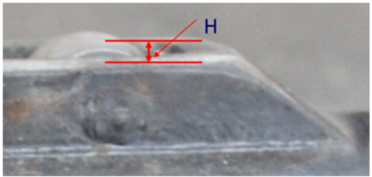
Roller and installing groove.
Functional testing
After testing the reliability, the functions of the designed tool should be examined and analyzed to achieve the purpose of friction reduction. In this article, an experimental apparatus for drill string dynamics is used to carry out functional testing. The experimental apparatus is mainly composed of rigid cement tank, drill string system, testing system, and power system, as shown in Figure 11(a).

Experimental apparatus for functional testing: (a) experimental apparatus, (b) drill string with the designed tool, and (c) cement tank.
Experimental apparatus
In the experiment, drill string was supported by rigid cement tank whose length is 25 m and inner diameter is 192 mm, as shown in Figure 11(b) and (c). Drill string system was composed of two Φ127-mm drill pipes and its total length is 18.5 m. As shown in Figure 12, tension–torsion sensor was installed near the motor to record the output torque of motor, and torque and axial force of drill string. Wireless data communication allowed real-time data transmission. Each sensor assembly comprised tension–torsion sensor, torque sensor, and vibration sensor. All the test data were collected and stored by software, and results were analyzed through curve graph.

Testing system.
In Figure 13, power system was mainly composed of motor (7.5 kW, 118 r/min, 569 N·m), Φ125-mm air cylinder, speed control box (frequency control), pressure-regulating valve, and base frame. The rotary speed of drill string was changed by speed control box, and the movement speed of drill string was changed by pressure regulating valve.

Power system.
Experimental results
In order to examine whether the designed tool can achieve the purpose of friction reduction, the test values of tension, compression, and torque should be compared when the tool is installed or not in the drill string. Figures 14–16 are the experimental results of friction reduction tool. The maximum working diameter of the tool is 204.5 mm which in bigger than the inner diameter of cement tank (192 mm), so the tool may be stuck in the cement tank in experiment. Excluding the abnormal test results, conclusions can be drawn as follows:
The average compressive force decreases from 730 to 410 N after installing the tool, a 44% decrease, as shown in Figure 14.
The average tensile force decreases from 640 to 370 N after installing the tool, a 42% decrease, as shown in Figure 15.
The average torque decreases from 270 to 100 N·m after installing the tool, a 63% decrease, as shown in Figure 16.

Comparison result of axial compressive force.

Comparison result of axial tensile force.

Comparison result of torque.
Field testing
It is a long period of development and experiment before a designed tool comes into use, and modifications and improvements are needed. The safety and reliability should be first ensured, and then its function should be achieved. For this purpose, field testing was carried out to examine its function in actual working conditions. The purposes of the testing include the following: (1) testing the reliability under downhole complex loads such as axial force, torque, bending force, and impact force; (2) modifying and improving the structure according to wear and erosion after testing; and (3) examine whether the tool can achieve the purpose of friction reduction (based on hook load).
Basic data of XP21-4 well
XP21-4 well is a directional well in Sichuan Basin of China. According to the surveying data, measured depth (MD) is 1306 m, true vertical depth (TVD) is 987 m, designed build-up rate is 15°/100 m, and the maximum inclination angle is 54°. In the drilling of second opening (232–1306 m), Φ215.9-mm bit is applied, weight on bit (WOB) is 60–100 kN, rotary speed is 35–50 r/min, and delivery capacity is 30–35 L/s. The testing was carried out in the second opening
Testing results
Drilling out plug in vertical section of second opening
The friction reduction tool was installed on drill string to carry out drilling out operation at 9:30 am, 2 July 2016. The BHA is as follows: Φ215.9 mm bit+430×410 crossover sub+411×410 back-pressure valve+Φ177.8 mm drill collar×27 m+411×4A10 crossover sub+Φ158.8 mm drill collar×18 m+4A11 ×410 crossover sub+Φ127 mm heavy weight drill pipe×32 m+411×410 friction reduction tool+Φ127 mm heavy weight drill pipe×108 m+Φ127 mm drill pipe+411×410 Kelly sub + 411×410 lower Kelly cock + 411×520 crossover sub + 133.35 mm Kelly.
The vertical section of second opening is 239–265 m. After drilling out and drilling to kickoff point, the total drilling time was 16 h eliminating trip. Figure 17 is the picture of friction reduction tool after drilling out. According to visual examination, there was balling phenomenon at rollers. Further analysis indicated that balling was not caused by drilling operation (pumping pressure: 9.5 MPa, delivery capacity: 30–35 L/s) but caused by scraping borehole wall in trip out the hole. All the parts of the tool worked properly and no wear was observed, so the friction reduction tool can be used in further directional drilling operation.

Friction reduction tool after drilling out.
Directional drilling second opening
The friction reduction tool was installed on drill string to carry out directional drilling operation at 11:00 am, 3 July 2016. The BHA is as follows: Φ215.9 mm bit+Φ172 mm 1.5° single bend positive displacement motor (positive displacement drill)+411×410 back-pressure valve+411×410 friction reduction tool+Φ165 mm non-magnetic drillcollar×9.13 m+411×520measurement-while-drilling system for directional drilling hanging sub+521×410 crossover sub+411×4A10 crossover sub+Φ158.8 mm drill collar×16 m+4A11×410 crossover sub+Φ127 mm heavy weight drill pipe×64 m+411×410 curved axis+Φ162 mm drilling jar+411×410 bypass valve+Φ127 mm heavy weight drill pipe×64 m+Φ127 mm drill pipe+411×410 Kelly sub+411×410 lower Kelly cock+411×520 crossover sub+133.35 mm Kelly.
The directional section of second opening is 260–1306 m. The total drilling time of the tool was 118 h. Figure 18 is the picture of friction reduction tool after testing. Some balling phenomenon was also observed at rollers.

Friction reduction tool after downhole testing.
Drag and torque were recorded in drilling in and trip operations of directional section, as shown in Figures 19–21. According to recorded results, WOB is 4–6 tons and friction is 3–6 tons in the well section of 756–927 m. WOB is 6–8 tons and friction is 9–12 tons in the well section of 1080–1306 m. Friction is 11–13 tons in trip out from 1295 to 991 m.
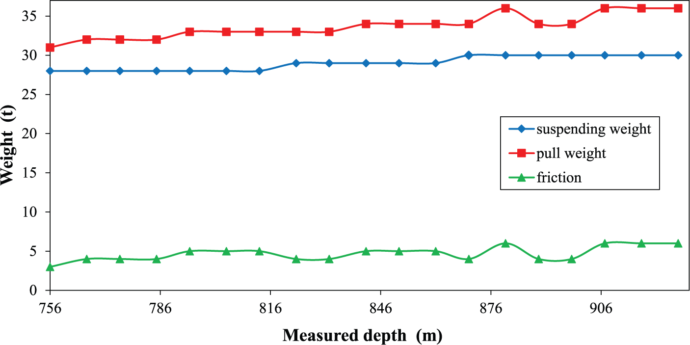
Friction in well section of 756–927 m (WOB: 4–6 ton).

Friction in the well section of 1080–1306 m (WOB: 6–8 ton).
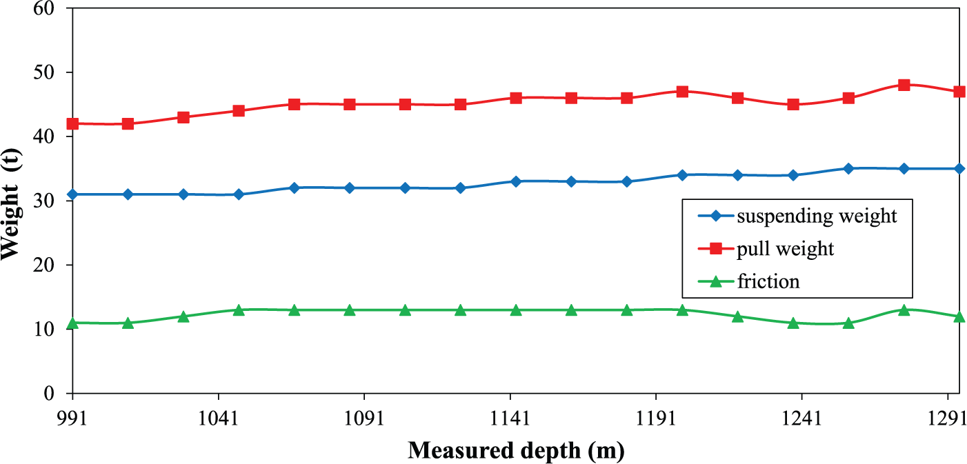
Friction in trip out from 1295 to 991 m.
Conclusion
A new friction reduction tool is designed and developed for horizontal wells. Numerical simulation of fluid flow and laboratory mechanical testing provides a scientific reference for field testing and application.
The results of the flow field analysis show that the rotation of the tool and the spiral guide groove has obvious disturbance effect on fluid, which can help cutting transport and reduce cutting-bed accumulation.
Tensile resistance of the friction reduction tool is up to 90 ton according to tensile experiment. Ultrasonic flaw detection indicates that there is no micro-crack on the tool after test. Shearing experiment indicates that large deformation of the pins is observed but they are not broken under the lateral load of 20 MPa.
Functional testing is carried out in an experimental apparatus for drill string dynamics. According to experimental results, the designed tool can achieve the purpose of friction reduction.
Field testing is conducted in XP21-4 well. Total downhole working time of the tool is 130 h and its fatigue life can reach 3×10⁵ cycles. Therefore, the structural design, material, and mechanical analysis of the tool are reasonable.
Footnotes
Academic Editor: Jun Ren
Declaration of conflicting interests
The author(s) declared no potential conflicts of interest with respect to the research, authorship, and/or publication of this article.
Funding
The author(s) disclosed receipt of the following financial support for the research, authorship, and/or publication of this article: The authors are grateful to the support from the National Natural Science Foundation of China (grant no. 51574198).