
Abstract
In this article, a new model of regenerative vibrations due to the deflection of the cutting tool in turning is proposed. The previous study reported chatter as a result of cutting a wavy surface of the previous cut. The proposed model takes into account cutting forces as the main factor of tool deflection. A cantilever beam model is used to establish a numerical model of the tool deflection. Three-dimensional finite element method is used to estimate the tool permissible deflection under the action of the cutting load. To analyze the system dynamic behavior, 1-degree-of-freedom model is used. MATLAB is used to compute the system time series from the initial value using fourth-order Runge–Kutta numerical integration. A straight hard turning with minimal fluid application experiment is used to obtain cutting forces under stable and chatter conditions. A single-point cutting tool made from high-speed steel is used for cutting. Experiment results showed that for the cutting parameters above 0.1mm/rev feed and
Keywords
Introduction
Turning operation is one of the most effective machining processes for the manufacturing of metal and non-metal components used in different industries. In turning operation, a cutting tool is fed into a rotating workpiece to generate an external or internal surface concentric with the axis of rotation. Turning is carried out using a lathe machine, one of the most versatile conventional machine tools. In turning, the cutting tool is held in on a translating carriage or turret or in the tailstock. The carriage or turret travels along the bedways parallel to the part axis (Z-axis) being machined.
The motion perpendicular to the part axis is provided by the X-axis or a cross slide mounted on the carriage. The workpiece is mounted on a rotating spindle using a chuck, collet, faceplate, or a mandrel, or between pointed conical centers.
During turning operation, the cutting tool experiences a deflection due to the cutting load exerted on its tip by the workpiece, the reason why cutting tool condition monitoring is a crucial factor in turning operation. Any inhomogeneity or misalignment of the cutting tool will cause small vibrations from such disturbances. Those disturbances will affect the mechanism of chip formation and variation of cutting forces so that self-excited vibrations are induced by the relative motion between the tool and the workpiece. Chatter in turning operation is undesirable because it limits the production rates and leads to machining defects. The large relative vibrations between the workpiece and the tool in turning process can compromise the productivity of this manufacturing technique. Numerous studies have been carried out on self-excited vibration of regenerative chatter type in turning operation. In 1965, Tobias 1 developed a regenerative machine tool theory where the cutting force was considered to be a function of both the current and the previous cuts. The theory of Tobias was accepted as the most appropriate to describe the regenerative chatter type phenomenon, and it has become a foundation of many theoretical and experimental kinds research up to date.
The theory of regenerative chatter has been the research subject of great interest in manufacturing processes. Chandiramani and Pothala 2 presented a numerical study involving machine parameters. They reported that chatter amplitude at first increase and then decreased when the cutting velocity or the uncut chip thickness is increased. E Budak andM Wiercigroch 3 presented a critical review of the state of the art for modeling and experimental investigation on the source of nonlinear chatter vibration generation and suppression in metal cutting. They found that the understanding of the physical phenomenon between the tool and workpiece is the key point in the modeling of the cutting process. Chatter vibrations have been a major issue in almost metal cutting process since the beginning of machining era. Recently H Wang et al. 4 investigated the influence of the tool-tip vibration on surface roughness during diamond turning. Their results reported that the high-frequency tool-tip vibration is the dominant factor affecting the surface roughness. A Mamedova et al. 5 presented a comprehensive force and deflection models for the milling process in order to estimate the deflection amount of the micro end mill occurred due to the cutting forces acting on the tool. Y Yuan et al. 6 proposed an innovative uncut chip thickness algorithm in order to predict the cutting forces in the micro end-milling process. The cutting force coefficient was identified as nonlinear functions of the uncut chip thickness, cutting edge radii, and the cutting velocity.
Zhang et al. 7 predicted the general three-dimensional (3D) cutting force components by considering cutting edge radius size-effect, tool run-out, tool deflection, and the exact trochoidal trajectory of the tool flute. The results showed that the cutting forces are significantly influenced by tool run-out and the tool deflection which leads to the reduction of the effect of tool run-out on cutting forces, particularly in thex- and y-axis directions. MA Salgado et al. 8 investigated on the stiffness of the system formed by the machine tool, shank and tool holder, collet and tool. The results of this study showed that the stiffness of both the machine and the clamping in the machine–spindle–tool holder–tool system have similar importance in the displacement of the tool-tip to the deflection of the tool itself. XT Duong et al. 9 proved that during a machining process, the tool life is influenced significantly by the machining characteristics such as cutting force, vibration, cutting temperature, chip formation, and tool wear behavior. M Siddhpura and R Paurobally 10 made a comprehensive review on the methods of control and chatter suppression in turning process. They affirm that regenerative chatter finds their source from the interaction between the cutting process and the machine structure. Self-excited vibrations are much more detrimental to finished surfaces and cutting tools due to their unstable behavior which results in large relative displacement between the tool and workpiece. J Chen and Q Zhao 11 evaluated the relative tool–workpiece vibration by considering machine tool error, cutting force material properties, and change in cutting parameters during single-point diamond turning operation. The analysis showed that the main factors affecting the relative tool–workpiece vibration are spindle speed, material properties, and tool wear. SJ Zhang and S To 12 studied the multimode high frequency of the tool in ultra-precision diamond turning. They indicated that the cutting force has a linear relationship with the tool vibration and the higher the tool’s frequency is, the smaller the effects of the tool vibration are. AM Khorasani et al. 13 provided a general static cutting tool deflection model for ball nose cutter. Deviation of machine components and the tool holder was neglected because they were very small. Their results proposed the three section model method as the one which showed high accuracy.
M Wan et al. 14 proposed an industry-convenient method of indirectly measuring cutting forces from deflections of the rotating tool shank. Results showed that cutting forces obtained by the proposed method are close to the reference values. B Denkena et al. 15 presented an approach for a monitoring and control system for the tool deflection for milling machine tools. The results showed that the deflection control increases significantly not only the milling accuracy but also the machining time. R Kishore et al. 16 developed and implemented an electro-magneto-rheological damper that can be used to monitor and control the process damping of the cutting tool in hard turning operation. The designed electro-magneto-rheological damper was highly competent for controlling cutting tool vibration in hard turning process and improved the cutting process in terms of the surface finish of the workpiece, reduced tool wear, and reduced cutting force. J Munoa et al. 17 presented a critical review of different chatter suppression techniques in metal cutting. Process solutions with design and control were compiled to provide a complete view of the available methods to stabilize the cutting process. Deflection and vibration of the tool-tip in machining processes affect the quality of the surface finish. P Twardowski et al. 18 presented a study on surface roughness analysis of hardened steel after high-speed milling taking into account milling parameters, force components, and the vibrations. The results showed that the dominant factor of the surface quality is the dynamic behavior and feed per revolution. P Nieslony et al. 19 investigated on surface quality and topographic inspection of variable compliance part after precise turning by the measurement of the stiffness of the machining system and the analysis of cutting force components. The results revealed that the process dynamics has a greater impact on the surface finish than turning kinematics and plastic deformation of the workpiece. S Wojciechowski et al. 20 proposed a new experimental method to estimate the ball end mill’s part vibrations by considering displacements correlated with the geometrical error of the tool–tool holder–spindle system and deflection caused by milling forces. The author’s results revealed that the surface quality formation is notably affected by the tool’s working part dynamic deflections caused by milling forces. P Albertelli et al. 21 used the method of Receptance Coupling Substructure Analysis (RCSA) approach in order to predict chatter-free cutting condition. The proposed RCSA allows a good prediction of the dynamic compliance and the relative stability lobe diagram (SLD) estimation considering a not previously dynamically characterized tool.
Y Ji et al. 22 developed a new RCSA methodology with the purpose of predicting the tool-tip dynamics. The established methodology solves the problem of accuracy in the estimation of the receptance. X Han et al. 23 demonstrated a dynamic model for vibration in the turning process. The workpiece was modeled as a beam rotating about its longitudinal axis and the cutter provides a moving load considered as a source of parametric excitation. The results indicated that the regenerative term has some effect on the dynamic response of the workpiece in the turning process.
The theory of chatter mechanism in metal cutting processes is known and described in the literature. The former chatter mechanism analysis is mainly for convention cutting where vibrations are associated with velocity dependence, cutting forces, and nonlinear dry friction between the tool and the chip. Some of the authors with significant contributions are Lipski et al., 24 Wiercigroch and Krivtsov, 25 and G Litak. 26 The later come out with chatter mechanism as a result of outer and inner modulation of the chip thickness. Among the authors with comprehensive literature, we can mention Fofana, 27 Stepan et al., 28 and Kalmar-Nagy and Wahi. 29 Nevertheless, the problem of obtaining high-quality final product to meet the industrial requirement during machining has not been solved yet. So, the next step is to identify and understand the basic physical phenomenon that takes place during the machining operation in order to achieve accuracy and quality demands.
Significant research works have been made in the field of chatter suppression and control during turning process. Important progress has been already made in tool monitoring and design. In the aforementioned research literature, the regenerative chatter was modeled as a result of cutting a wavy surface from the previous cut. Using knowledge available from the smart structures research of the previous authors, in this article, a dynamic model is presented for regenerative chatter vibration as a result from different positions of the cutting tool due to the tool deflection during turning. Compared to deflection of the tool, the deflection of the spindle, tool holder, and the workpiece were very small and they have been neglected in this study. The tool was loaded as a cantilever beam to estimate its permissible deflection under the action of the cutting load. The dynamic machining model of the tool under deflection was established. Tool vibration was analyzed using a single-degree-of-freedom (SDF) oscillator. The workpiece was considered to be rigid. The model takes into consideration various forces acting on the system such as inertia force, damping force, spring force, and the cutting forces.
Materials and methods
Tool deflection estimation by simple cantilever beam model
The cutting tool is assumed to be loaded as a cantilever beam by cutting forces at the end cutting edge.


Schematic diagram of the cutting tool deflection.
To understand the direction of the tool deflection, equation (1) for static deflection has been introduced. The deflection will be maximum at the free end (see Appendix 2)

The negative sign indicates that the deflection is downward. The downward deflection at the free end

Analysis of dynamic model vibration
Figure 2 shows different positions of the cutting tool with respect to the workpiece due to the deflection of the cutting tool. Chip formation under unstable conditions results in variation of excitation cutting forces which lead to the regenerative chatter vibrations. 30

Dynamic model of machining under cutting tool deflection.
The thickness of the chip that is cut is the difference between the current position of the cutting tool and the position of the cutting tool one revolution earlier.
The cutting force components with regenerative chatter vibration are derived from experimental data obtained during turning of several workpieces 31 and take the form of


where
During turning, the cutting force is applied on the tool-tip, that cutting force was resolved into three components for easy exploitation. In this article, the tool nose radius has been selected as

Diagram of regenerative chatter due to cutting tool deflection.
If


where


where
By considering a 1-degree-of-freedom model of the motion of the cutting tool presented in Figure 3, in the direction perpendicular to the workpiece, the equation of motion of the system is

Equation (7) can be written in terms of current position

Variation of excitation cutting forces due to the instantaneous chip cross section is expressed as

The equation of motion takes the form

where
After linearization of cutting forces variation

where
The solution in the first approximation for nonlinear ordinary differential equation (11) is

where
3D finite element model analysis
Modeling is the art of representing the object or a system. The finite element model analysis (FEMA) is expressed as the method of representation of a structure using graphical and non-graphical information. The method is able to generate the mathematical description of the geometry and non-geometry of the constructed structure in the computer database and an image of an object on the graphics screen. Material properties of the structure under consideration are essential inputs for a FEMA. Based on its potential to accommodate more general geometric and material assumptions, there has been a long interest in using FEMA to analyze machining.
LISA FEA software is a complete suite and perfect for simulating, analyzing, optimizing, and validating various materials used in industry field. This software addresses the broadest range of issues and design geometry associated with FEMA. There are three stages of simulation in LISA finite element analysis technology. The first stage-based simulation is called “build the model.” The geometric model is created then meshed using triangular mesh elements which are automatic mesh generation. The material is selected and is set for simulation by treating it as a rigid material. For finishing this first stage, it is also required to set the process conditions on the software. The next stage is “solve the model.” The type of analysis is defined, then various governing equations are performed and applied to the model for analysis. The last stage is called “display the results,” where the experience of the analyst is required to extract the reliable and most important information from multiple colored contour results offered by the simulation software. This stage is very important for the efficiency of the simulation model.
In this article, Figure 4 shows the finite element model of a single-point cutting tool made from high-speed steel (HSS) to be analyzed. The finite element model of the tool was generated using analysis static 3D element. The cutting tool was initially straight. Its material was homogeneous and isotropic; the stress–strain relationship is linear and elastic. Young’s modulus is the same in tension as in compression. The cutting loads measured during experiments were applied to the tool-tip according to the real situation and related deflections are recorded in Table 3. The cutting tool deformation was only considered. The temperature effects have not been taken into account. A finer mesh was used to demonstrate a more accurate result. Constraints on the non-cutting side were applied to fix the cutting tool and prevent any movement based on the real situation of tool holding in turning operation. For easy calculation and physical discretization, there will be more nodes in order to reduce errors because the grid has more units. The cutting tool physical parameters characteristics are specified in Table 1.
The cutting tool material parameters.
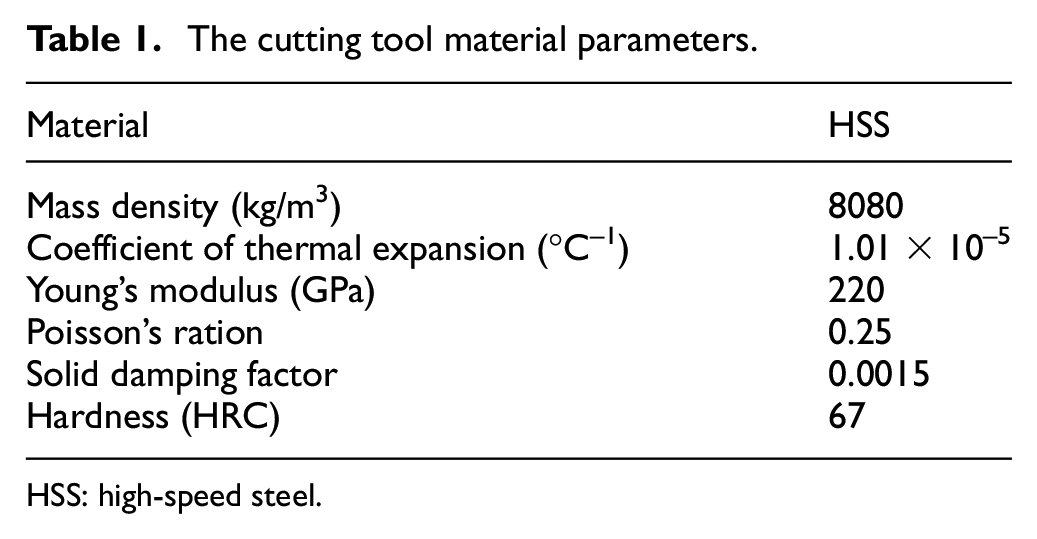
HSS: high-speed steel.

FEMA of the cutting tool subjected to the cutting load.
Experimentation
Cutting forces are an important parameter which influences the tool deflection and characterize the turning operation. Metal turning is a complex process which includes a lot of nonlinear effects such as material constitutive relations (stress vs strain, strain rate, and temperature), tool-structure nonlinearities, friction at the tool–chip interface, and the influence of machine drive unit on the cutting flow velocity. Because of the complex nonlinear phenomenon involved in metal cutting, the analytical force model cannot sufficiently predict accurately all-important phenomenon of the cutting force dynamic components. In this article, the experimental procedure was adopted as an accurate method to obtain the variation of cutting forces by considering all nonlinear parameters and to distinguish between cuttings under stable and chatter conditions.
Experiment setup
Experiments were carried out on a two-axis SMT500 CNC lathe machine tool. The idea behind the experiment was to minimize the effects of all the factors that influence the cutting tool deflection and vibration. Straight hard turning with minimal fluid application procedure was chosen because of its advantages in reduction of tool vibration, cutting forces and it provides better cutting performance compared with conventional wet and dry turning as reported by the study on the influence of fluid application parameters on tool vibration and cutting performance during turning by P Sam Paul et al. 36 (Figure 5). In the experiment, the workpiece material was mild steel. Mild steel is the most important material and has wide application in many industrial fields. A cylindrical specimen with the diameter D = 40 mm, length L = 400 mm was prepared and mounted in the chuck of the lathe headstock and machined at different cutting parameters. The workpiece material parameters are described in Table 2 and the experimental conditions are summarized in Table 3.

Turning process experiment setup.
The workpiece material parameters.

Data of measured cutting forces and related tool deflection.
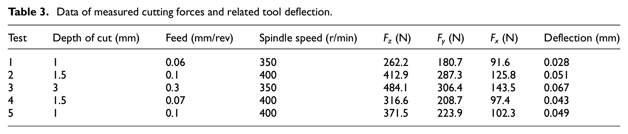
A solid type single-point cutting tool made from HSS was used for cutting. Generally, a high percentage of all cutting operation of the steels is carried out using HSS. It is because of its good resistance to high compressive stress imposed on the tool and which may become higher enough to deform the cutting edge and destroy the tool. The tool parameters were tool nose radius of 0.2 mm, back rake angle of 12°, end cutting edge angle of 30°, and side rake angle of 12°; the tool length was 100 mm, with an overhang of 40 mm. The selection of the tool parameters aimed to minimize the vibration frequency as reported by T Eswara and G Bala Murali 37 in the study about the vibration of single-point cutting tool made in HSS during turning. A Kistler 9252A three-component piezoelectric dynamometer was mounted on a SMT500 CNC lathe machine tool, and the method is known as the direct method of force measurement. The Kistler was mounted with a pre-loading force. A14-bit multifunction Data Acquisition (DAQ) card (PCI-6132; National Instrument) was installed on a PC workstation to convert the analog signals of the cutting forces. For easy identification and interpretation, the output signals of the dynamometer were amplified by a charge amplifier. The obtained data were recorded on PC using DAQ system Dynoware. For further data processing, Excel and MATLAB were used. Each series of cutting test was repeated four times to ensure the accuracy of results in the experiments.
Results and discussion
Analysis of dynamic model vibration results
A single-point cutting tool with 1 degree of freedom is presented in Figure 3 which describes the cutting system dynamics. The intended chip thickness is

Periodic response (a) and frequency response (b) for the amplitude,

Quasi-periodic response (a) and frequency response (b) for the amplitude,
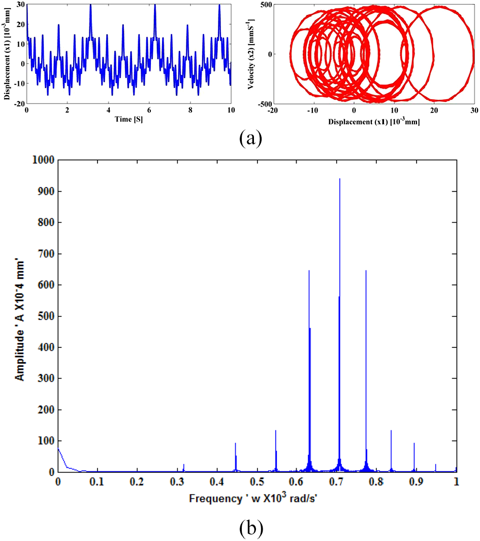
Chaotic response (a) and frequency response (b) at the amplitude,
Figure 7 shows unstable cutting process with large frequency
Using nonlinear time series, we identified the frequencies that may lead to chaotic motion. The identification is useful for developing reliable methods for controlling and minimizes chatter vibrations. When the frequency is sufficiently small, the response of the system will be a simple harmonic motion, that is, the phase plane will be an ellipse. For large frequency, additional harmonics beyond the fundamental are detected and the phase plane will be distorted from a simple ellipse and the nonlinearities in equation (15) enormously amplify the errors in the initial conditions of the system.
3D FEMA results
The results of 3D FEMA are shown in Figure 9. The cutting tool was considered as one end fixed cantilever beam with an overhang of

3D FEMA results of deflected cutting tool.
The cutting load of
Experimental results
We start by defining the geometry of process and the description of measured quantities. Figure 10 shows the necessary coordination system including cutting forces in

Diagram of cutting forces during turning process.
Experiments were performed by changing the cutting parameters namely rotational speed, feed, and the depth of cut. The diameter of the workpiece was kept constant in all experimental series. Figures 11–13 indicate the results for measured forces signals in time history and their corresponding frequency domain. In the time history, the vertical axis indicates the magnitude of cutting force in Newton and the horizontal axis indicates time in seconds. In the frequency domain, the vertical axis shows the amplitude of tool vibration in millimeters and the horizontal axis shows the tool vibration frequency in radians per second. From the time history results, it is clear that the main cutting force component makes a great contribution in the cutting process dynamics. Note that the main cutting force component makes a bigger influence of the cutting stability.
4
To identify stable and chatter cases, main cutting force component signals were processed and transformed from time history plots to frequency domain plots by fast Fourier transform (FFT). The chatter frequency and amplitude can be clearly seen from the m6ain force component frequency domain plots. The data of measured cutting forces was processed and the average values of the cutting forces denoted by

Time history (a) and frequency domain (b) of measured cutting forces during stable cutting condition (fewer fluctuations) at

Time history (a) and frequency domain (b) of measured cutting forces during unstable cutting conditions at

Time history (a) and frequency domain (b) of measured cutting forces during unstable cutting condition with large fluctuations at
Figure 11 shows the results obtained at
Figure 13 shows results for the cutting forces at the feed per revolution of
Figures 12 and 13 show the oscillating cutting forces which indicate the vibration instability of the machining system and the nonlinear interaction between the end cutting edge of the cutting tool and the workpiece. The variation of dynamic chip thickness due to the change of cutting tool position caused by deflection varies at the frequency of vibration and creates a vibrating cutting force which could amplify the vibration of the cutting tool.
Conclusion
In this article, the dynamic model of regenerative chatter due to the cutting tool deflection in turning operation was analyzed. The analysis was carried out using 1-degree-of-freedom model of the regenerative cutting. We observed that cutting tool deflection results in the complex dynamic behavior of the system because of nonlinear interaction between the tool and workpiece which leads to chatter vibrations. The obtained chatter vibrations transit from periodic, quasi-periodic, and chaotic type. For the case of cutting parameters, it was proved that an increase in feed and depth of cut decrease the machining stability. The experiment has shown cutting forces under stable and chatter cutting condition. The permissible magnitude of the tool deflection under the action of the cutting load has been obtained by finite element analysis. The system nonlinearities are associated with cutting forces. The experimental results have shown a good agreement with dynamic simulation results on the growth of chatter amplitude and frequency between the tool and the workpiece. The results of this article can serve as a foundation for the selection of cutting parameters to improve cutting dynamics performance as obtained from experiment and dynamic simulation results. Control methods of chatter vibration due to tool deflection need to be developed and it will be the author’s next research project. In spite, the analysis was based on a very simple model of regenerative chatter theory, but we believe that this study provides an important mechanism of cutting instabilities in turning operation.
Footnotes
Appendix 1
Appendix 2
The bending moment at the distance
The differential equation of elastic line is
By integrating both sides, we get
Integrating again on both sides
Now applying boundary condition on the fixed end which is at the distance
From equation (15)
From equation (14)
Solving equations (16) and (17), we get
Therefore, from equation (15)
The deflection will be maximum at the free end, and hence,
We get
The negative sign indicates that the slope is downward.
The downward deflection at the free end
Acknowledgements
The authors gratefully acknowledge the administrative team in the School of Mechanical and Electronic Engineering, Lanzhou University of Technology, for facilitating the access of all equipments and materials used in the experiments.
Handling Editor: James Baldwin
Declaration of conflicting interests
The author(s) declare no potential conflicts of interest with respect to the research, authorship, and/or publication of this article.
Funding
The author(s) disclosed receipt of the following support for the research, authorship, and/ or publication of this article: This study was funded by the National Natural Science Foundation of China (grant no. 11372122) and the Science and Technology Program of Gansu Province of China (grant no. 1610RJYA020).