
Abstract
Tool deflection induced by cutting force could result in dimensional inaccuracies or profile error in corner milling process. Error compensation has been proved to be an effective method to get accuracy component in milling process. This article presents a methodology to compensate profile errors by modifying tool path. The compensation effect strongly depends on accuracy of the cutting force model used. The mathematical expression of chip thickness is proposed based on the true track of cutting edge for corner milling process, which considers the effect of tool deflection. The deflection of tool is calculated by finite element method. Then, an off-line compensation algorithm for corner profile error is developed. Following the theoretical analysis, the effect of the error compensation algorithm is verified by experimental study. The outcome provides useful comprehension about selection of process conditions for corner milling process.
Introduction
The demands of low tolerances and better quality products have forced manufacturing industry to continually progress in quality control and machining technologies.1,2 In mold manufacture, the shape of cavity molds can be complex, containing highly diverse and irregular characteristics. 3 Corner is a typical geometric feature in automobile panel mold, and the feed direction is changing continuously in machining process. 4 There are multiple error sources which cause inaccuracy. Tool deflection is an important source of machining error. 5 It will reduce dimensional and geometric accuracy for the finished workpiece. So, it is necessary to analyze the deflection behavior in the cutting process. Error compensation is proved to be an effective method to improve the surface accuracy for corner machining process. 6 A number of researches have concentrated on dealing with the reduction of tool deflection error induced by cutting force, and error compensation has been conducted to improve machining accuracy.7–9 The machining error compensation techniques could be summarized into the following steps: predication of cutting force, tool deflection induced by cutting force and conducting error compensation.10,11
Predication of cutting force
Kim et al. 12 established a mathematical model to analyze the three-dimensional form error of a ball end milled surface due to the elastic compliance of the cutting tool. For the flat-end milling process, the first documented work which considered the complex chip geometry as a result of the cutter deflection feedback was done by Sutherland and Devor. 13 Ikua et al. 14 developed a theoretical model for cutting forces and machining error in ball end milling of curved surfaces. The actual trochoid paths of the cutting edges were considered in the evaluation of the chip geometry. Feng and Menq 15 proposed a cutting force predicate model which took into account the instantaneous feedback of cutting system deflections to chip geometry, so the cutting force calculation algorithm had a higher accuracy. To control the accuracy of machining processes, Zheng et al. 16 developed a three-dimensional model of cutting forces in peripheral end milling process. The experimental data from end milling tests were presented to assess the fidelity of the analytical model. Wu et al. 17 built the cutting force model by combining the infinitesimal and experiential methods. The model included the mill engagement arc, feed rate and helix angle of the cutter as variables. The establishment of force model provides the foundation for predication of the tool deflection. It should be noted that, for some models mentioned above, the cutting forces were calculated with an assumption of a rigid machining system. The effect of cutting system deflections is not considered in the calculation of the cutting forces.
Tool deflection induced by cutting force
Calculation of tool deflection is a key step for machining error compensation. Dow et al. 18 predicted the cutting forces and applied these forces to calculate the shape error due to tool deflection, then the machining error was eliminated by creating the new tool path. Soori et al. 19 presented a virtual machining system to enforce dimensional, geometrical and tool deflection errors in three-axis milling operations. They proposed a method to calculate tool deflection using neural network method, but this method needs to do a lot of training experiments for different workpiece-tool combinations. Zeroudi and Fontaine 20 developed a tool deflection calculation and compensation methodology based on a recent model developed for the prediction of cutting forces in free-form milling, and good compared results were observed between experiment and simulation results. To get more accurate machined profile, Kline et al. 21 first equalized the cutter to cantilever beam model to calculate its elastic deflection. Also, to predict the machining error caused by geometric error of machine tool structures, a variety of modeling methods have been developed.22,23 However, through these approaches, it is difficult to understand the relationship between each cutting parameter and tool deflection. So, further research on error compensation should be conducted.
Compensation of machining error
To improve the machining accuracy, the application of error compensation is an effective methodology. Ramesh et al. 4 summarized the machining error source for different processes, and then the corresponding compensation methods were proposed. Ma et al. 24 carried out the research on tool deflection error compensation in five-axis ball end milling process, and the compensation reference can be modeled to optimize the tool paths. Based on differential evolution algorithm, a novel hybrid optimization approach was established for milling process by Yildiz.25,26 The significant improvement for machining accuracy was obtained with the hybrid technique in comparison with the results by other algorithms. After that, the research on optimization of cutter parameters for machining process was conducted. 27 Cho and Seo 28 used polynomial neural network in determination of mean surface error and then compensating the same using tool path modification techniques. The result showed that the proposed approach was an important alternative for optimization of machining parameters in milling operations. Zeroudi and Fontaine 20 proposed a new error compensation method that’s based on solving tool deflection for free surface machining.
There is another method to improve machine tool position accuracy, which is online error compensation. Yazar et al. 29 used the online adjustment feed rate method to control machining error in the milling process, and the research results improved the machining accuracy obviously. Yang and Choi 30 proposed a method of using the tool path online adjustment to get high machining accuracy. Li et al. 31 developed an efficient modeling and compensation method for the synthetic geometric errors of large machine tools. Their results showed that the position accuracy of the tool-tip was affected by all the translational axes, and the machining precision could be improved by 85% after error compensation. However, the application of online method should have secondary development with the commercial computer numerical control (CNC) system. It may be a complex cost-effective way to improve machine tool accuracy.
Many efforts have been made in the past to conduct error compensation for milling process, and researches are of great significance in improving machine tool accuracy. However, few of them were concentrated on machining process of curved geometries. Dotcheva and Millward 32 analyzed the contact relation at different stages in corner milling process. The process was divided into cutting, cutting in and cutting out stages. The instantaneous cutting force was calculated using the maximum chip thickness during every cut. Wei et al. 33 used the equivalent feed rate to express the value and direction of the actual real feed rate along the curve path, which improved the prediction accuracy of the corner milling process. Bera et al. 34 conducted the research on error compensation in flexible end milling of tubular geometries. Also the effectiveness of error compensation for synclastic and anti-clastic configurations was done conducted by them. Law and Geddam 35 proposed a process-design approach for compensation strategy to reduce the surface error during machining of pocket. The tool deflection error was reduced to 20–25 µm by the proposed cutting method. For milling of curved geometries, Rao and Rao 36 proposed compensation of surface error due to cutting force-induced tool deflections. The results indicated that surface errors due to cutter deflections can be reduced by 65%–78%, which was useful in many industrial scenarios.
An important observation made from review of previous research attempts on deflection compensation in milling process is that the studies mainly dealt with straight geometries. However, the feed direction in corner machining process keeps changing, that means the tool deflection induced by cutting force becomes more complex. This will result in the change in instantaneous chip thickness. Therefore, this factor should be taken into account in the prediction of cutting force.
In this article, to get a higher accuracy machined profile in corner milling process, a flexible system model for predicting cutting force is presented. The effect of the cutting force on chip geometry for the particular workpiece and cutter combination is revealed. Then, an improved cutting force model is developed. The machining error due to the cutting system deflection is evaluated for the corner milling process. Following the theoretical analysis, verification experiments were performed. Compared with the corresponding measured data, the experimental results show that the profile accuracy is much better than that without compensation. The outcome of this research work furnishes good insight into controlling the surface error in corner milling process.
Characteristic analysis of corner milling process
Phase division in corner milling process
The cutting tool moves along the tool path in the corner machining process. Schematic diagram for the corner milling process is shown in Figure 1, which details the milling process by example. The ball end mill is adopted in this research. The corner milling process begins at the point B and it stops at the point C. When the cutter position is before point A or after point D, the radial cutting depth
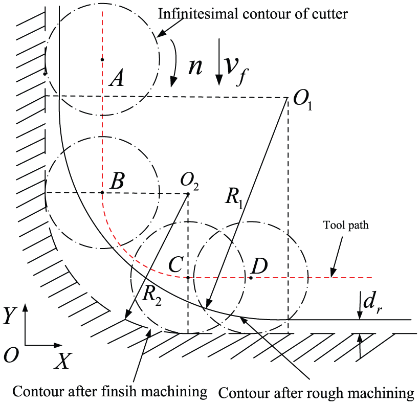
Separated states of corner milling process.
For precision corner machining process, the ball end mill is relative to the origin of the workpiece coordinated system. Assuming the workpiece coordinate system is
The real trajectory of cutter in corner milling process
In the corner milling process, the ball end mill rotates around the tool axis vector as it moves along the circular tool path. The trajectory of a point on the cutting edge of a ball end mill is hypocycloid. The expression is
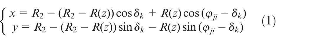
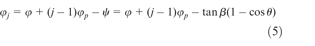
where δk is the angle at which the cutter turns around the radius of the corner. The position angle of the infinitesimal cutting edge of ball end mill is

where φ0 is the initial position angle. Generally, φ0 = 0°, j is the number of cutting edge, φp is the angle between teeth, φ is the rotation angle of the cutter and µ is the lag angle between the tip and a point on a cutting edge.
The center points of the cutter along the tool path is
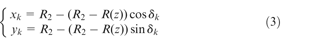
Then, the movement trajectory of the tool tooth and center could be simulated using the software MATLAB. The result is shown in Figure 2.
Cutting edge cycloidal trajectory and tool path trajectory.
The chip thickness model in corner milling process
Instantaneous chip thickness is a key point to establish a prediction model for cutting force. The accuracy of the cutting force model is also determined by chip thickness. The method of instantaneous chip thickness is solved using the real track of tool cutting edge in this article.
Traditional model of the chip thickness
Generally, the instantaneous chip thickness is a function that depends on the feed per tooth

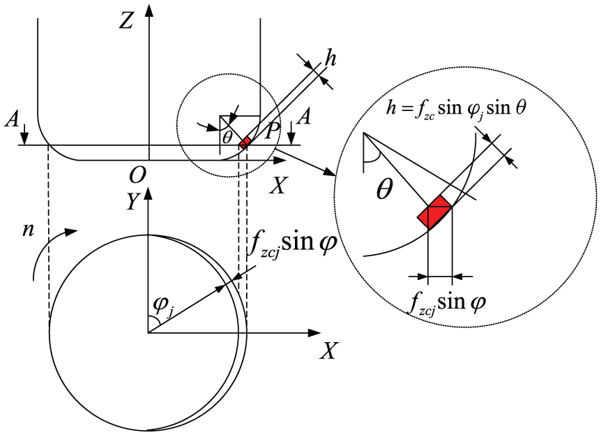
Geometric relations of instantaneous chip thickness.
In equation (4),
Here,
In milling process, the feed direction is perpendicular to the normal direction of the circular arc, so the feed rate of each tooth will change continually. The instantaneous chip thickness model could be modified as

In equation (6),
Improved model of the chip thickness
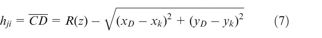
According to the analysis of the real trajectory of the cutter, the instantaneous chip thickness can be defined as the distance of the machined surface between the current cutting edge and the prior cutting edge. In Figure 4, the instantaneous chip thickness consists two segments. The chip thicknesses in different segments have been calculated and the results could be referred in Liu et al. 3
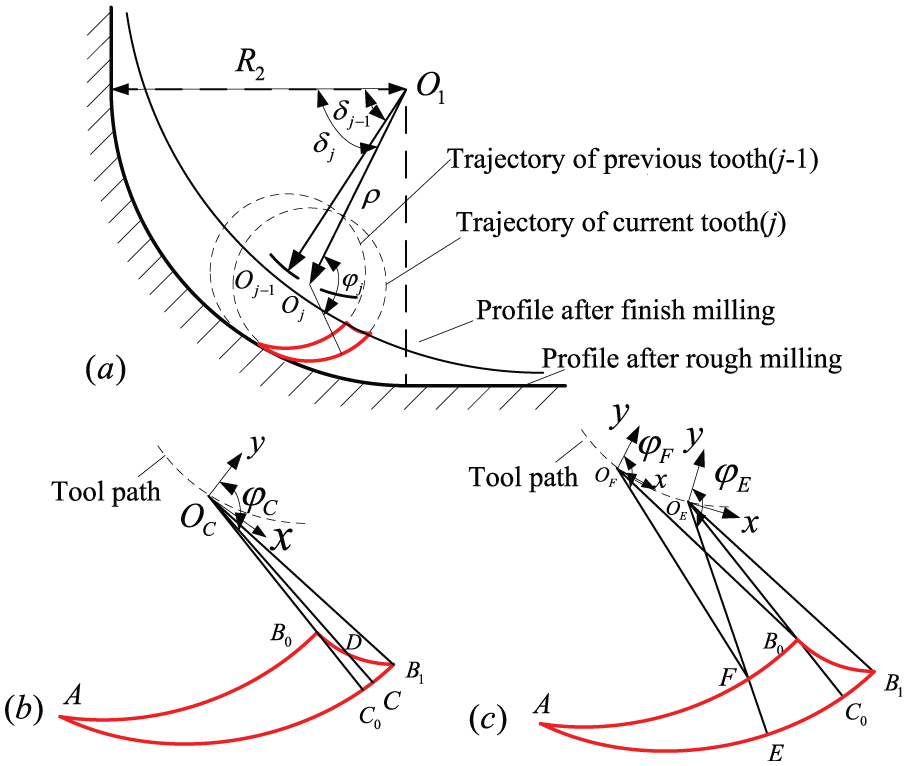
Chip thickness model for corner milling (a) sketch (b) Case 1 (c) Case 2.
Case 1. The infinitesimal cutting edge in
Case 2. The infinitesimal on cutting edge in
Prediction and verification of cutting forces
Prediction of cutting force
The whole corner is divided into a series of instantaneous processes. The instantaneous process is the milling process for one cutter tooth. Each instantaneous process can be considered as a static milling process. In order to calculate the instantaneous cutting force changing with tool rotation angle in each static milling process, the cutting edge is discretized in the direction of the cutter axis. In a three-dimensional space, the infinitesimal cutting force could be discretized into the tangential force
where
The integral part of the infinitesimal cutting force is implemented in the effective contact area, and the complete cutting force model will be obtained.
Verification of cutting force model
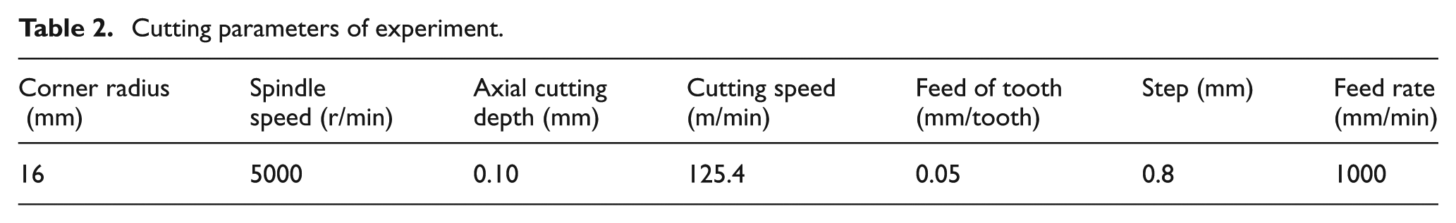
In order to verify the accuracy of the cutting force model, a specific experiment was done. The experimental test system includes an Emco Concept Mill 450 machine tool and dynamometer system. The dynamometer system is made by KISTLER Company, whose type is 9257B. The workpiece material is hardened steel Cr12moV, whose hardness is HRC 58–60. The processing center and experimental equipment are shown in Figure 5. Donghua test software is used for cutting force data acquisition. The tool geometric parameters and machining parameters used in this experiment are shown in Tables 1 and 2.
Experiment setup.
Tool parameters of ball end mill.
Cutting parameters of experiment.
The cutting force model was simulated by software MATLAB. If the cutting parameters are selected as in Table 2 for experimental research, the comparison of simulation and experimental results for three-component cutting force are shown in Figure 6. The left side is the simulation results, and the right side is the experimental results. When the cutter is milling the corner, the force in X-, Y- and Z-directions will increase after straight stage. The reason is that the radial cutting depth becomes larger and the contact angle is greater than tooth spacing angle. Before the previous cutting edge cuts out, another cutting edge began to participate in the milling process, which will lead two cutting edges to cut at the same time.
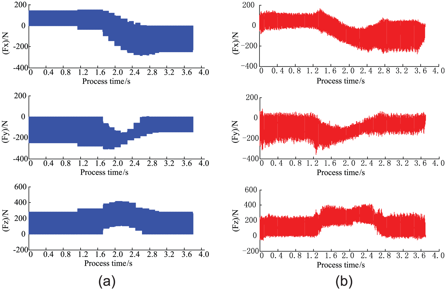
Compared cutting forces (a) simulation results and (b) the experimental results.
The change in experimental result of cutting force lags behind the simulation result. This is because changes in radial cutting depth and feed direction cause the vibration of cutter, and the cutting time will be prolonged. The comparison shows that the simulation results of cutting force have a good fit with the experimental results in magnitude and trend.
Compensation of profile error
Deflection of tool system
Generally, the tool holder and the spindle have sufficient rigidity. The mill cutter can be assumed as a cantilever beam with a fixed end. The cantilever beam is divided into three parts on the basis of the cross-section shape of the ball end mill, as shown in Figure 7.
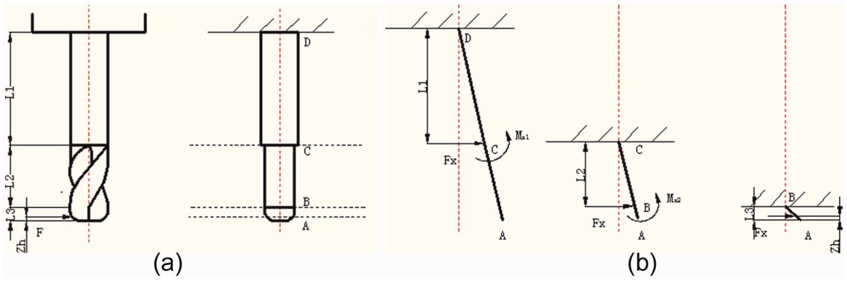
(a) Structure of ball end mill and (b) equivalent cantilever beam model.
If the equivalent cantilever beam is effected by more than one force, its deflection is the algebraic sum of deflection of each force. Then, the deflection of ball end mill could be expressed as
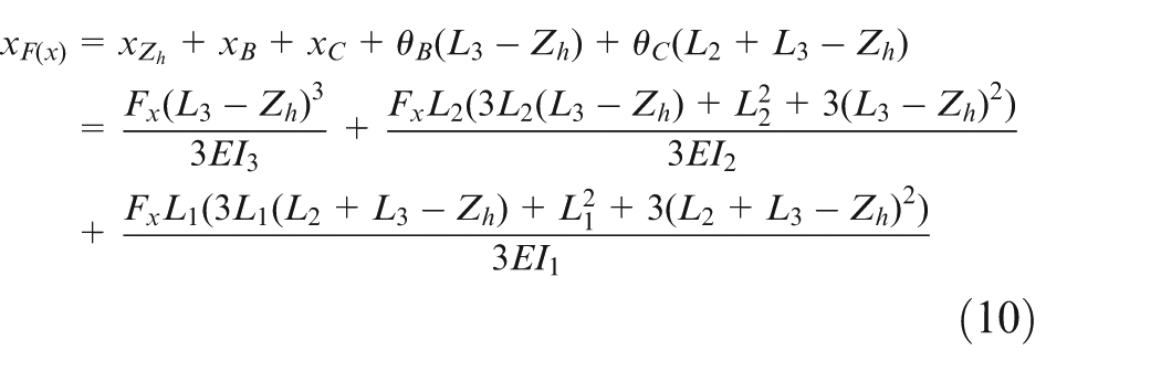
Here, E is elasticity modulus of tool material. L is the length of the cantilever, L1, L2 and L3 are shown in Figure 7. E1, E2 and E3 are the inertia moments of L1, L2 and L3 segments of cutting tool.
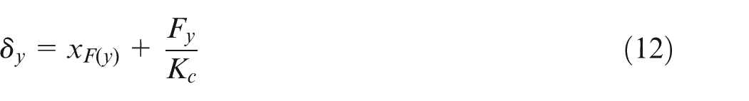
Due to the tool overhang length, helix cutting edge length and tool material properties have been known, and they are imported into ANSYS software. Because the geometrical parameters of the cutter are known, the calculation of cutter inertia could be carried out according to Lee and Altintaş. 37 In order to obtain high accuracy model, tool clamping deflection system was taken into account in tool deflection prediction. Because the axial rigidity of the tool system is large enough, the deflection in Z-direction was ignored, which was caused by cutting force in the axial direction. The deflection of tool system in X- and Y-directions can be expressed as

The computer-aided design (CAD) model of the rounding corner cutter is established to calculate tool deflection, and the calculation result by the finite element method (FEM) is shown in Figure 8(a). This two fluted cutter is considered as elastic, homogeneous and isotropic. Its Young’s modulus E is 600,000 MPa and Poisson’s ratio ν is 0.28. The mesh chosen for the tool is linear tetrahedral type. The boundary conditions are specified so that one end of the tool is fixed and the other is free. If the corner rounding cutter is imposed a cutting force FX, then the deflection amount in the X-direction will be received. As it can be shown in Figure 8(b), the variation of the calculated tool deflection in X-direction is obtained by FEM.
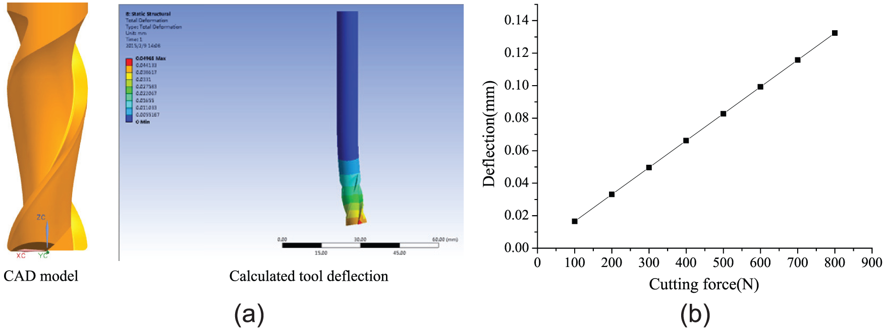
Calculation result of tool defection: (a) FEM simulation (b) deflection result in X-direction.
Improved model of chip thickness
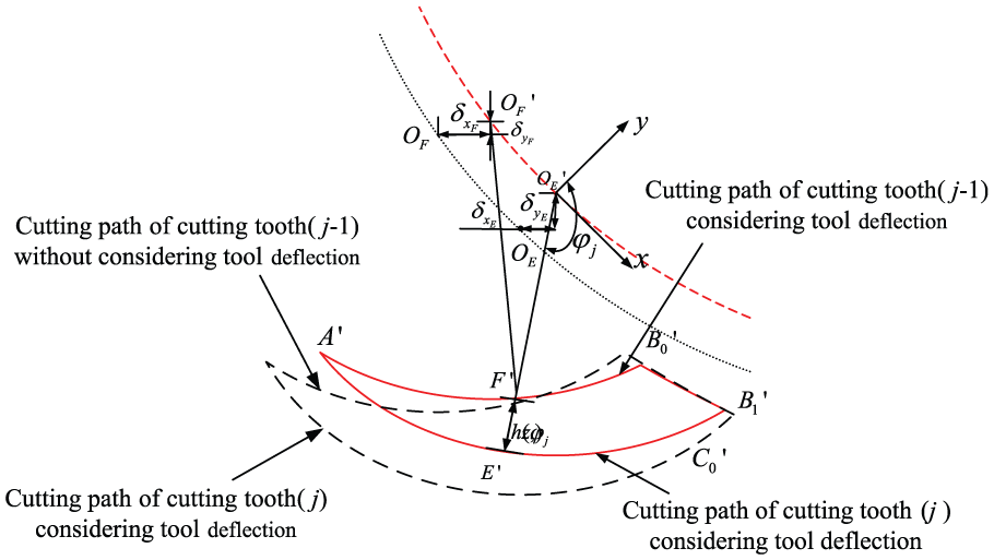
In this research, to get the effect of the deflection tool system on instantaneous chip thickness, not only the impact of the cutting force of current cutting edge on instantaneous chip thickness is taken into account but also the effect of previous cutting edge on cutting chip thickness. The change in instantaneous chip thickness is based on the repeated iteration process of the tool system which is caused by the cutting force, as shown in Figure 9.
Influence of tool deflection on the transient chip thickness.
Delay distortion will affect the cutting process of current tool edge, so its effect should be considered for establishment of improved instantaneous chip thickness model. Assuming the tool angle is
When the tool deflection caused by cutting force is considered, the cycloidal trajectory equation of the cutting edge can be expressed as
Then, the improved instantaneous chip thickness could be expressed as follows
Algorithm of error off-line compensation
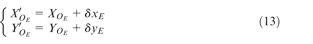
As the cutting force causes cutter system deflection, the tool center will deviate from the ideal tool path position. The offset method is used to reduce the machining error. The method is that the tool center along the tool path is offset opposite to the tool deflection direction in X- and Y-directions. But the change in the tool center position can lead to the change in contact angle and the instantaneous chip thickness, which leads to change in the cutting force and deflection of the tool path. So the iterative error compensation operation should be performed on each tool path until the error is less than the allowable error for the corner machining surface. The flowchart of error compensation steps is shown in Figure 10.
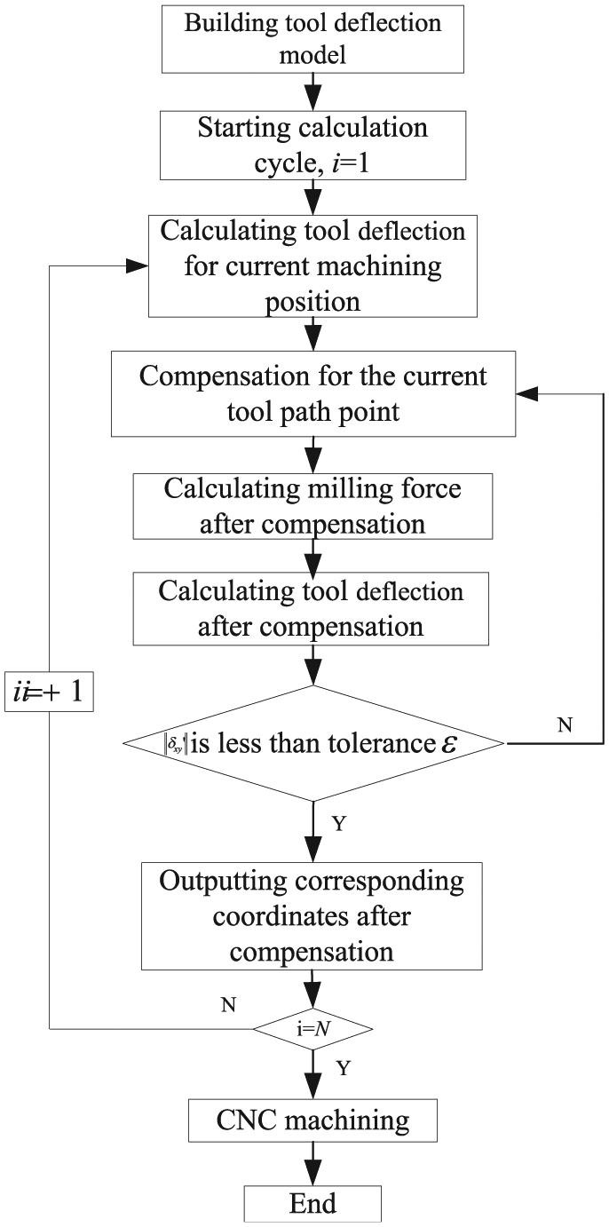
Flowchart of profile error compensation.
The machine surface profile contour of with and without compensation are drawn using MATLAB software as well as the ideal profile, as shown in Figure 11. It can be found that the surface profile after compensation is closer to ideal surface contour than before. That is, the milling process with compensation has higher accuracy than without compensation, so the algorithm is verified to be effective.
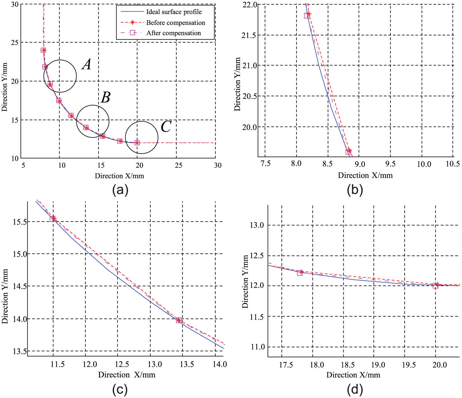
Corner surface profile before and after error compensation: (a) comparison result, (b) local zoom A, (c) local zoom B and (d) local zoom C.
Verification of machining error compensation
The error compensation effective algorithm and accuracy of machining force prediction models are verified by experiment. In order to compensate the compensation effect, the workpiece is divided into two parts: the left side is machined without compensation and the right side is machined with profile error compensation. The processing parameters of the experiment are shown in Table 1, and the processing conditions are as same as the cutting force verification experiment. The machined surface profile is shown in Figure 12. The comparison of the two profiles shows the effectiveness of the tool trajectory compensation.
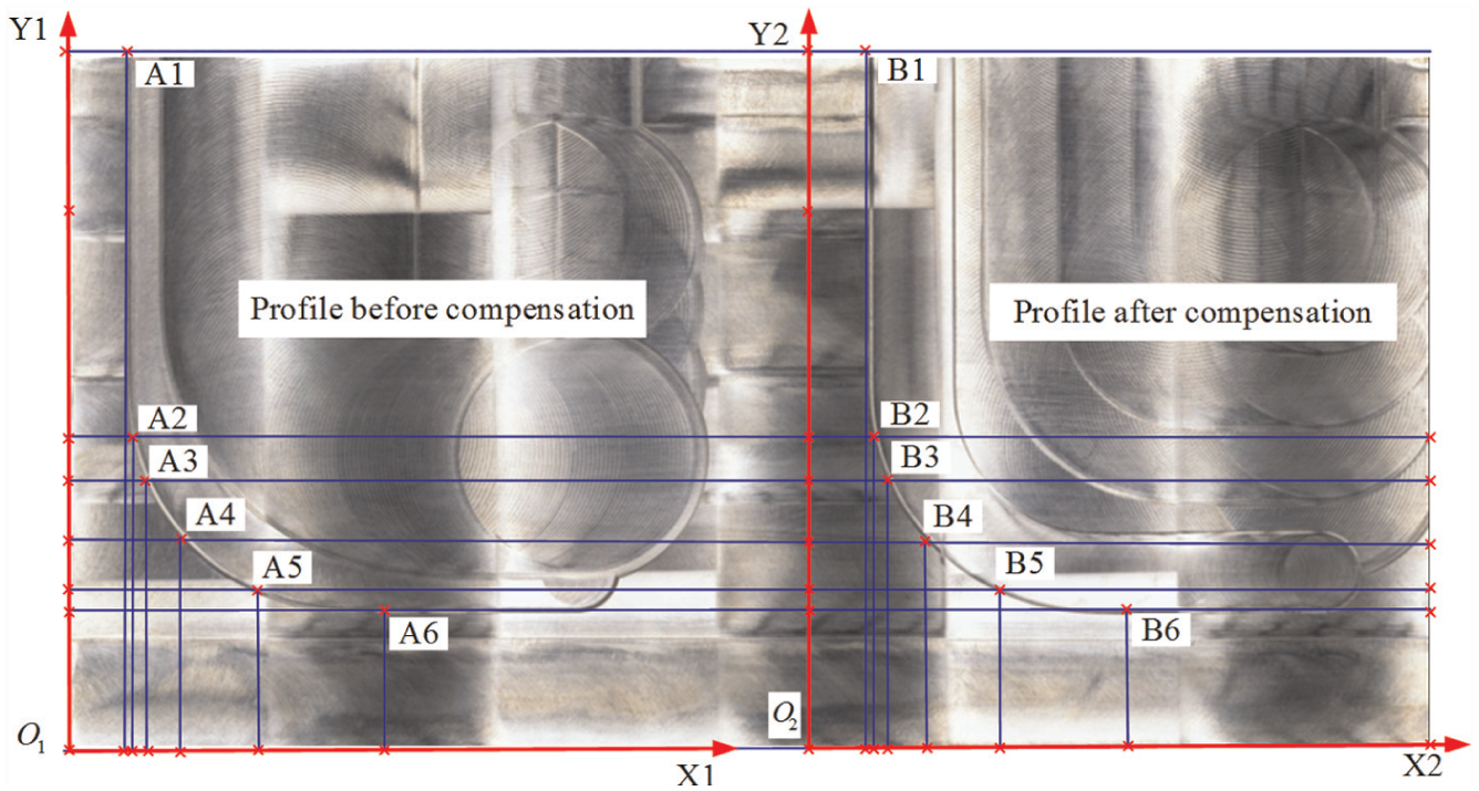
Comparison chart of processed profile.
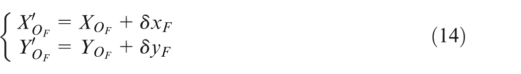
The measuring coordinate system was established for machined workpieces, and their origin coordinates are
Comparison of measured points coordinate before and after error compensation (µm).
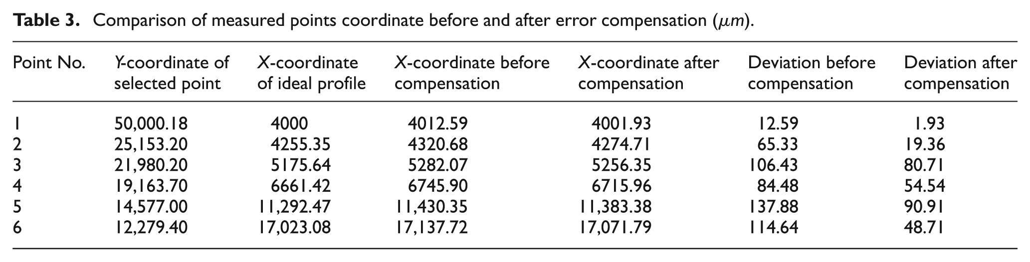
As shown in Table 3, the deviation is significantly remedied after error compensation. The most obvious effect of error compensation could be up to 85% for machining precision. So, the proposed error compensation algorithm can effectively improve the accuracy of the corner surface size by data analysis. However, due to measurement error and processing error, there is profile error still after compensation. Compared with the surface profile without compensation, the accuracy has been improved significantly, and the compensation effect is satisfactory.
Conclusion
This research presents an off-line tool path compensation strategy for improvement of profile accuracy in milling process of corner. The cutting force predictive model is based on deflection-dependent chip geometry modeling method. The cutting force experiment result shows that the prediction result of cutting force model is consistent with experimental result. Based on the cutting force simulation result, the tool deflection in corner milling process is obtained by FEM. According to the characteristics of the cavity corner, an iterative algorithm is proposed to compensate the machining profile error. Machining experiments and profile error measurements were made to assess the effectiveness of proposed tool path compensation methodology. The result indicates that the profile accuracy of machined corner can be improved remarkably using proposed compensation methodology, and the most obvious effect of compensation could be up to 85%. The outcome provides useful comprehension about selection of process conditions for corner milling process.
Footnotes
Declaration of conflicting interests
The author(s) declared no potential conflicts of interest with respect to the research, authorship and/or publication of this article.
Funding
The author(s) disclosed receipt of the following financial support for the research, authorship, and/or publication of this article: This project was supported by National Natural Science Foundation of China (Grant Nos 51575147 and 51235003) and Science Funds for the Young Innovative Talents of HUST (No.201507).