
Abstract
In the process of face-turning high-temperature alloy Inconel718 with carbide tools and ceramic tools, the change rules of cutting force were studied and the empirical models of cutting force on the cutting parameters were established. For the tools, the main cutting force has positive relation to both the feed rate and the turning depth. Variation trends of the axial force are in accordance with the increase in these two parameters. During the increasing process of the cutting speed, the feed force changes slightly while the main cutting force decreased about 96 N when using the carbide cutter. For the ceramic cutter, the main cutting force and the axial force increased to about 380 N first and then decreased when the cutting speed increased. The axial force affected not only the processing parameters but also the geometrical parameters of the cutter. There exist some relationships between component forces.
Introduction
Nickel-based superalloy Inconel718 which is widely used in the key components of aviation engines has excellent high temperature strength, anti-oxidation, creep resistance and corrosion resistance performance, and good fatigue properties. High-temperature alloy is a typical kind of difficult-to-cut material due to its large cutting force, high cutting temperature, serious work hardening, characteristics of sticking cutter, and the severe tool wear during the machining process. A lot of research of its machinability has been made by domestic and foreign scholars.
Madariaga et al. 1 carried out a face-turning experiment on Inconel718 using carbide inserts with big nose radius. Experimental results show that the main cutting force increases with the increase in feed while decreases with the increase in cutting speed. The feed force almost has no relationship with the cutting speed, and the axial force increased with the increase in feed and cutting speed. C Li 2 carried out a turning experiment on Inconel718 using cubic boron nitride (PCBN) tools and established the prediction model of cutting force. It can be found that the increase in cutting depth and feed rate lead to the increase in cutting force, while the increase in cutting speed made the cutting force appear a trend of getting smaller. J Yang et al. 3 simulated the turning process of Inconel718 using deform three-dimensional (3D) finite element analysis software and analyzed the cutting forces under different cutting depth and cutting speed levels. The analysis results showed that the cutting force decreases obviously when the cutting speed increases from 113 to 526 m/min. DW Sun 4 studied the effect of cutting parameters on cutting process by orthogonal method when the cutting speed was in the range of 162–291 m/min and established the prediction model of cutting force. At the meantime, the influence law of cutting parameters on the cutting force was obtained and the optimization of cutting parameters was realized. XL Zhu 5 studied the influence law of cutting parameters on cutting force when dry turning Inconel718 using carbide coated tools when the cutting speed was in the range of 30–50 m/min. The moderate cutting speed, small cutting depth, and small feed rate should be selected during the turning process from the point of view of controlling the cutting force. Thakur et al. 6 found that the reasons why the main cutting force is slightly larger than that in the feed direction and the decrease of them are the decrease of the contact area and the decrease of shear strength due to the increase of temperature under an increase of the cutting speed. The tangential force and the feed force generally showed a linear relationship when the cutting speed was in the range of 45–55 m/min. The effects of cutting speed and tool geometry on the cutting force were studied by Nalbant et al. 7 The main cutting force reduced by 14.6% when the cutting speed increased by 60% and reduced by 10.4% when the cutting speed increased by 20% when the cutting speed was in the range of 150–250 m/min. The minimum value of the main cutting force was observed at a speed of 250 m/min, and the cutting force increased with the increase in the nose radius. Choudhury and El-Baradie 8 carried out an orthogonal dry cutting experiment on Inconel718 using uncoated and coated carbide tools. They found that the cutting force increases with the increase in cutting speed, but decreases with the increase in the depth of cut and feed. XJ Xu et al. 9 established the Inconel718 finite element cutting model based on orthogonal cutting experiments and compared the different time-domain curves of the cutting force caused by the different tool radii and tool rake angles. The research showed that the plow effect made the feed force increase. The feed force increased by 7% when the tool radius changed from 0 to 5 µm. DS Ji and XH Huang 10 carried out an orthogonal cutting experiment on Inconel718 with coated cemented carbide tool KC5510 and obtained the empirical formula of cutting force. The most influential factor which can affect the cutting force is feed rate. FY Yu et al. 11 established the empirical model of cutting force of turning superalloy Inconel718 with coated carbide tools. The results showed that the factors which exert impact on the cutting force in the decreasing order are as follows: the cutting depth, feed, and cutting speed. Y Li and CB Cai 12 studied the variation rule of cutting force when using PCBN tool cutting nickel-based superalloy. The effect of the tool rake angle, back angle, cutting speed, and feed on the cutting force was analyzed through the establishment of the simulation model of turning nickel-based superalloy Inconel718 with PCBN tools. YS Zhai et al. 13 researched the change rules of cutting force under different cutting parameters by the simulation combining with the comparison of experiment of the cutting process of superalloy Inconel718 with PCBN tool. Cica et al. 14 studied the prediction technique of turning force under different sets of cutting parameters and cooling conditions.
To conclude, scholars have made a lot of research works in order to improve the machining efficiency of Inconel718. The ceramic tool which has higher allowable cutting speed and greater wear resistance performance represents the development direction of the cutting tool for new type of difficult-to-cut material. This article established two kinds of empirical model of cutting force on cutting parameters when turning high-temperature alloy Inconel718 using coated cemented tool and coated ceramic tool. The effect of the cutting parameters and tool geometry parameters on the cutting force and the relationship between the component forces has been analyzed. The study in this article will provide reference for the controlling of the surface integrity of parts and the tool wear from the point view of controlling the cutting force in manufacturing process.
Experimental conditions and solutions
Workpiece material and cutter
Workpiece material is nickel-based superalloy Inconel718DA. Its main chemical components were Ni (52.82%), Gr (19.0%), Go (0.16%), Mo (3.0%), Al (0.8%), C (0.08%), Si (0.35%), Mn (0.35%), Nb (5.0%), Ti (0.6%), and Fe. Mechanical properties are as follows: the microhardness is about 480 HV, the tensile strength is 1489 MPa, the yield strength is 1319 MPa, the elongation is 20%, and the shrinkage rate is 46%.
The face-turning experiment was carried out on Inconel718 with Sandvik-coated cemented carbide and KENNA-coated ceramic blade. The details of the blade are shown in Table 1. The DCLNR 2525M 12 type cutter produced by Sandvik was used in this experiment.
Cutter parameters.

Experimental procedure
The turning experiment was carried out with the method of three factors at four-level orthogonal test. The cutting parameters are shown in Tables 2 and 3, v represents the cutting line speed, ap represents the depth of cutting, and f represents the feed rate. The cutting speed of carbide tool was in the range of 40–70 m/min, and the cutting speed of ceramic tool was in the range of 60–90 m/min. The size of the sample was Φ30 mm × 100 mm. The experiment was carried out on the HK63/1000 (the maximum power is 11 kW) numerical control lathe. The Blasor emulsion was used for cooling in the turning process.
Measurement results of cutting force with carbide tool.

Measurement results of cutting force with ceramic tool.

Cutting force testing
The face-turning process carried out under different sets of processing parameters is shown in Tables 2 and 3. The cutting force was measured at the meantime. Figure 1 shows the following forces: the main cutting force, the feed force, and the axial force.Figure 2 displays the Kistler 9257B data acquisition card (test range ± 5 kV) and the Kistler 5080A multichannel charge amplifier which were used in this test.
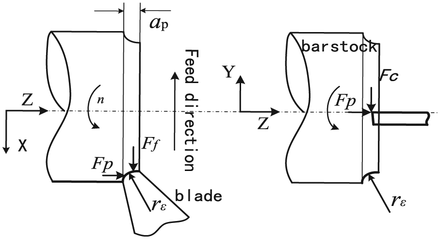
Sketch of cutting forces.

Photo of dynamometer.
Results and discussion
Empirical model of cutting force
Figure 3 shows the instantaneous cutting force curves obtained in experiment when v = 70 m/min (carbide blade) or v = 90 m/min (ceramic blade), ap = 0.4 mm, and f = 0.20 mm/r. The cutting force increased rapidly and then entered a process of steady state. The values of cutting force in steady state are shown in Tables 2 and 3.

Measurement results of cutting force: (a) carbide blade (v = 70 m/min, ap = 0.40 mm, f = 0.20 mm/r) and (b) carbide blade (v = 90 m/min, ap = 0.40 mm, f = 0.20 mm/r).
As shown in formulas (1) and (2), the empirical model of the cutting force on cutting parameters was established by the method of multiple linear regression based on the test data.
Empirical model of the cutting forces of the carbide blade

Empirical model of the cutting forces of the ceramic blade

The models were significant and acceptable through the significance tests with the method of F-test.
Analysis of the influence of cutting parameters on cutting force
Figures 4 and 5 were established based on the data shown in Tables 2 and 3. They displayed the changing trends of the cutting force during the increasing process of the values of the cutting parameters. The Ff of the carbide blade changed little, and the main cutting force Fc gradually decreased about 96 N when the cutting speed raised to 70 m/min. For the ceramic tool, the main cutting force and the axial force changed almost along with the same trends: increased to about 380 N slightly first and then decreased. The gradual increase in the cutting force can be considered as a result of the serious hardening of the machining surface since the work hardening has more influence than the thermal effect during the machining process of high-temperature alloy using ceramic cutting tools when cutting speed was smaller than 70 m/min. When the speed was greater than 70 m/min, on one hand, more and more heat was accumulated in the machining process, so the thermal effect played a dominant role; on the other hand, a micromelted layer 15 formed at the bottom of the chip at high temperature. The friction coefficient of the contact area between tool and chips reduced accordingly. This directly lead to the increase in shear angle and the reduction in the deformation coefficient of chip. The cutting force on the unit cutting area was also reduced, so the cutting force gradually decreased.

Changing of the cutting force with the increasing processing parameters (carbide blade): (a) changing of the cutting force with the increasing cutting speed, (b) changing of the cutting force with the increasing depth of cut, and (c) changing of the cutting force with the increasing feed rate.
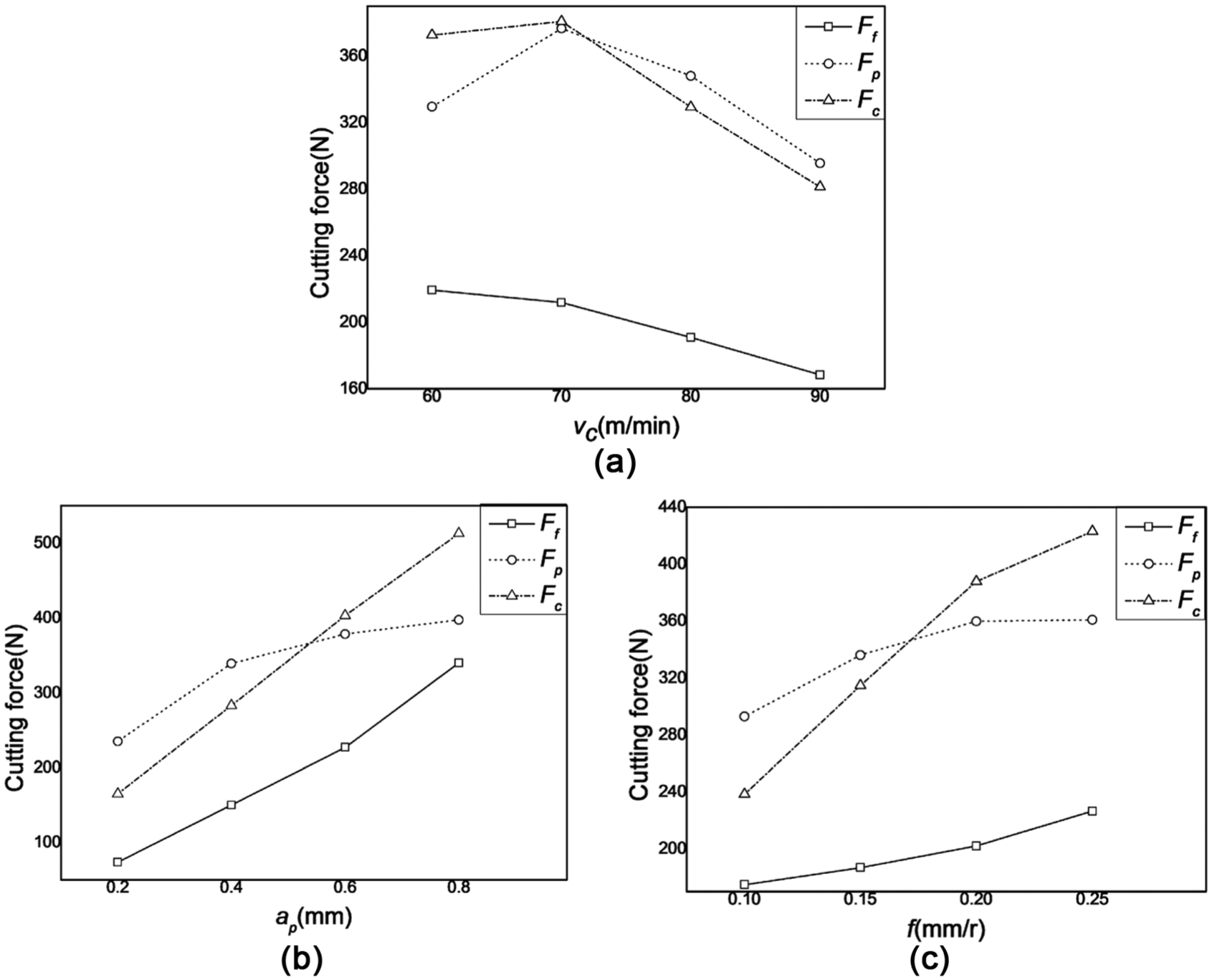
Changing of the cutting force with the increasing processing parameters (ceramic blade): (a) changing of the cutting force with the increasing cutting speed, (b) changing of the cutting force with the increasing depth of cut, and (c) changing of the cutting force with the increasing feed rate.
Figures 4 and 5 show that Fc is almost positively correlated with the ap and f. This is because the cutting area Ac increased linearly 16 with the increase in both of them. When either parameter increases, the material removal rate per unit time becomes larger, the force that the chip deformation required becomes bigger, so the cutting force becomes larger. The change trends of the axial force Fp with the change in both of them are almost identical. The impact of the Ff is less than the effect of the ap.
Analysis of the influence of tool geometric parameters on the cutting force
In the traditional cutting theory, the main cutting force is the largest in the three component forces. However, this relationship is not invariable. Fp is bigger than Fc in several sets of cutting force which were contrary to the classical cutting theory. This phenomenon was especially obvious when using the ceramic tool. Madariaga et al. 1 found the similar phenomenon in the process of cutting Inconel718. Liu et al. 17 found this phenomenon in the process of hard cutting bearing steel. They attributed this phenomenon to the tool geometric parameters, such as the radius of the tool edge redge.
The cutting force is essentially determined by the area of the cross section of the un-deformed chip, and the area is determined by the nose radius rn, turning depth ap, and feed rate f. As is shown in Figure 6, the shaded part is the cross section of the un-deformed chip.
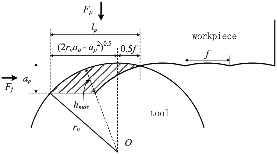
Cross section of un-deformed chip.
The maximum value of the thickness of the un-deformed chip hmax can be expressed by this formula 18 according to the geometric relation

This article comprehensively considered the cutting force situation when cutting with two kinds of tools and the value of hmax was in the range of 50–250 µm.
If the cutting force was divided by the area of the cross section of the un-deformed chip, the ratio cutting force (or ratio cutting energy) in this area can be obtained, which can expressed by u. It is the area of the shaded part in Figure 6 and can be expressed as 18

To explain the relationship between the axial force and the main cutting force, hmax/redge can be defined as a parameter which related to the sharpness of the cutting edge. The values of the ratio cutting force and hmax/redge under different sets of cutting parameters are shown in Tables 2 and 3.
Figure 7 shows the relationship between ratio cutting force and hmax/redge. For the carbide tool, Fp was slightly bigger than Fc, but there was no clear difference between them when hmax/redge is less than 3.2. The main cutting force was greater than the axial force when hmax/redge is greater than 3.2. This is because the cutting area becomes larger, so the consumption of power increased. This made the main cutting force greater than the axial force.

Specific cutting forces of axial force and main cutting force: (a) carbide blade and (b) ceramic blade.
The axial force was greater than the main cutting force if the value of hmax/redge was in the range of 0.5–2.0 when using ceramic tool. This can be explained with the great effect of plow phenomenon on the axial force. The plow effect was significant because the radius of the cutter edge was large. When hmax/redge was greater than 2.0, the main cutting force was greater than the axial force, but the amplitude was not larger than that when using carbide tool. This can be attributed to the impact of the performance of the tool. The axial force was still big when the turning depth and feed become larger because the seismic behavior and impact resistance ability of the ceramic tool are much worse than the cemented carbide tool. Hence, Fp is also affected by the cutter geometric parameters not just the processing parameters, such as redge. The cutter geometric parameters exert a larger impact on Fp than on Fc.
Liu et al. 17 considered that the reason why the ratio of Ff and Fp increases is the rise of the tool nose radius. The whole cutting area becomes thin and wide accordingly when the tool nose radius becomes bigger. As is shown in Figure 6, lp was defined as the width of the un-deformed chip and ap as its height. Define ap/lp as the width-to-height ratio of un-deformed chip. The scope of the ap/lp this article studied was: 0.30–0.94 for carbide tool and 0.25–0.67 for ceramic tool. The values of ap/lp under different sets of cutting parameters are shown in Tables 2 and 3.
Figure 8 shows that the Ff/Fp was proportional to ap/lp. The ratio k was about 0.98 (the black line in Figure 8(a)) for the carbide tool and 1.14 (the black line in Figure 8(b)) for the ceramic tool. The cutting speed has no much effect on k. The k should be close to 1.0 (the red lines in Figure 8) if the pressure on the cutter edge was uniform and the flow direction of the chip was perpendicular to the long axis of the un-deformed chip region. To summarize, the influence of the cutter geometric parameters on the cutting force cannot be ignored. There exist some relationships between the different component cutting forces. The tool nose radius and tool edge radius played important roles in them.

The relationship between the feed force, axial force, and the shape of the un-deformed chip: (a) carbide blade and (b) ceramic blade.
Conclusion
According to the cutting force model established, the depth of the cut exerted the greatest influential effect on the cutting force, the feed exerted the second, and the cutting speed exerted the least.
For the carbide tools, Ff changed little while Fc reduced about 96 N with the increasing cutting speed; For the ceramic tool, the changing trends of Fc and Fp with the increasing cutting speed were almost unanimous: increased slightly at first and then decreased. The increase in the cutting force results from the serious hardening of the machining surface when v was less than 70 m/min. The effect of the heat accumulated and the micromelted layer made the cutting force decrease when v was greater than 70 m/min.
For both the kinds of tools, Fc was positively correlated with ap and f because the cutting area increases when either of them increased. The changing trends of Fp with these two parameters are consistent. The depth of the cut ap exerted the greatest influential effect on the cutting force, f exerted the second, and Vc exerted the least.
Fp is slightly bigger than Fc when hmax/redge is less than 3.2, while Fc became greater than Fp when hmax/redge is greater than 3.2 because of the increase in the cutting area when using carbide tool. Fp was greater than Fc because of the plow effect result from the large cutter edge radius when hmax/redge was in the range of 0.5–2.0. When hmax/redge was greater than 2.0, Fc was larger than Fp because of the poor seismic behavior and impact resistance ability of the ceramic tool.
Footnotes
Appendix 1
Academic Editor: Xichun Luo
Declaration of conflicting interests
The author(s) declared no potential conflicts of interest with respect to the research, authorship, and/or publication of this article.
Funding
The author(s) disclosed receipt of the following financial support for the research, authorship, and/or publication of this article: This work was supported by the National Science and Technology Major Project of China (No. 2014ZX04012013).