
Abstract
To study the influences of processes factors on cutting force and vibration in cutting processes, milling tests were carried out on 022Cr17Ni12Mo2 stainless steel under different process conditions using a coated carbide end mill insert. The cutting force and vibration acceleration signals were recorded, and the wear depth on the flank face of the tool was measured. This study observed tool wear morphology using a scanning electron microscope and investigated distributions of surface elements on the damaged tools by energy spectrum analysis. Based on the revelations of tool wear mechanisms, the influence of milling parameters and tool wear on cutting force and vibration were further investigated. The research shows that oxidation, adhesion and diffusion wear mainly appear on the rake face, along with mechanical and thermal cracking, while adhesive and diffusion wear occur on the flank face. Among process factors, tool wear and milling depth significantly affect cutting force and vibration. Therefore, in actual machining processes, on the premise of meeting the requirements for rigidity and surface roughness of a machine tool, properly increasing the cutting velocity and milling depth can improve productivity and control cutting force and vibration.
Introduction
In a cutting process, many factors can lead to cutting vibration. These factors include changes in the frictional force between chips and tools and between tools and workpieces, uneven hardness of metals within the cutting layers, low installation rigidity of tools, poor rigidity of workpieces, occasional appearance of built-up edges and vibration due to selection of an inappropriate cutting depth. When tools cut into workpieces, the machined materials are deformed and become chips. This process needs to overcome the resistance of machined materials to elastic and plastic deformation and friction forces of chips to the rake face and the flank face to transitional surfaces and machined surfaces, thereby forming the cutting force. Cutting force and vibration can impinge upon normal cutting processes, generate chatter marks on machined surfaces and reduce the surface quality of machined parts. Furthermore, they can also accelerate tool wear and loosen connections between parts such as machine tools and fixtures, thus influencing rigidity and precision and shortening service life. In addition, noise produced by vibration can pollute the environment, impair the health of operators and even influence cutting processes. To decrease cutting forces and avoid vibration or reduce its intensity, the cutting depth has to be reduced sometimes, so that machine tools and tools cannot reach their full performance, which limits the cutting efficiency of some machine tools. Tool wear, cutting force and vibration, as important factors affecting machining quality and cutting efficiency of machine tools, have been studied widely.1–5 In cutting processes, there are many factors, such as the precision of machine tools, tool materials, geometric angles, internal structures of workpieces, cutting parameters and environmental factors, influencing cutting forces and vibration. Of them, machine tools, machining methods and workpiece and tool materials are fixed factors, while cutting parameters and tool wear are variable factors. 6 After determining factors including machine tools, workpieces and machining methods, the main factors influencing cutting forces and vibration are cutting factors and tool wear.
022Cr17Ni12Mo2 stainless steel is a material that is typically difficult to machine. It exhibits a high tenacity and thermal intensity, as well as a low thermal conductivity. Furthermore, it is liable to undergo significant plastic deformation, severe work hardening and generates much heat during cutting, and the heat is hard to be dissipated, so the tool tip operates at a high temperature and chips are liable to adhere to the cutting edges. As a result, built-up edges are easily produced. In view of these situations, scholars across the world have conducted tests on high-speed milling technologies suitable for use on 022Cr17Ni12Mo2 stainless steel and the associated tool wear. Using the single-factor method on the cutting velocity, Gao et al. explored the influences of cutting velocity on the quality of machined surfaces of austenitic stainless steel workpieces and cutting mechanisms of coated tools. They also found that tool wear mainly occurs on the rake face approaching the tip and adhesive wear is the dominant wear mode. 7 Zhou et al. conducted a high-speed dry milling test using hard carbide tools. By employing a scanning electron microscope (SEM) and an energy spectrum analyser, wear morphologies of tools and element distributions on wear surface and wear edge were observed and analysed, respectively. In addition, they also revealed the main wear mechanisms of both the rake and flank faces of the tool. 8 Based on the analysis of material characteristics, Zhang et al. 9 investigated the typical wear patterns and wear mechanisms of blades in cutting processes and obtained relatively superior tool materials, grades and cutting parameters through the comparative testing of tool wear and durability. Using four coated carbide tools to cut austenitic stainless steel 1Cr18Ni9Ti, Liu et al. studied the influences of cutting depth on cutting force and compared the cutting forces of the four tools. They found that when the cutting is performed with small feeds and shallow back-cutting depths, the back force is larger than the main cutting force. 10 Using a kinetic equation, Li et al. determined that four cutting parameters, including spindle speed, axial cutting depth, feed rate and radial cutting depth, are the main factors affecting milling vibration according to each parameter in the equation. Through orthogonal cutting tests, they sorted the weights of each cutting parameter and their effect upon milling vibration and concluded that cutting velocity is the principal factor affecting milling vibration. 11 Altintas et al. analyse the factors affecting milling vibration and determined that spindle speed and axial cutting depth are major factors therein. Moreover, they found the stability curve for milling controlled by these two factors. 12 Although scholars have carried out many studies on wear mechanisms, cutting forces and vibration of efficient cutting tools for 022Cr17Ni12Mo2 stainless steel, they mainly focus on overall hard carbide tools while seldom studying the wear characteristics and mechanisms governing the behaviour of coated carbide inserts. Furthermore, the comprehensive influencing characteristics of milling parameters and tool wear on cutting force and vibration lack systemic research. Using coated carbide end mill inserts to mill 022Cr17Ni12Mo2 stainless steel, this study further investigates the influence of process factors on cutting force and vibration on the basis of revealing tool wear mechanisms. This provides theoretical and technical support for those seeking to optimise process factors in the machining of 022Cr17Ni12Mo2 stainless steel.
Experimental conditions
Workpiece materials
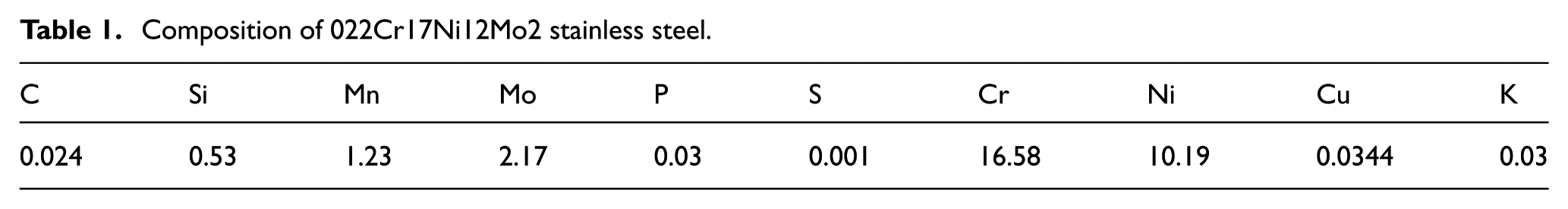
Square blocks of 022Cr17Ni12Mo2 stainless steel produced by Taigang Stainless Steel Co., Ltd, China, were used in the experiment. The length, width and height are 420, 320 and 100 mm, respectively. The chemical composition of the cold-rolled steel is summarised in Table 1. The main mechanical properties are as follows: the tensile strength
Composition of 022Cr17Ni12Mo2 stainless steel.
Tool materials and geometrical parameters
The coated carbide tool, with two teeth, was made in Germany and was used to machine these 022Cr17 Ni12Mo2 stainless steel samples. The tool bar and blade types are 90W25-3K13 and APMT 1135 PDER-M B4025, separately. The geometrical parameters of the blades are shown as follows: the rake angle, clearance angle, edge inclination angle, front clearance angle, auxiliary angle and tool nose radius were 14°40′, 11°, 4°39′, 16°, 5° and 0.5 mm, respectively. The diameter of the tool used in the experiments is 16 mm. Figure 1 illustrates the tool bar and blade used in the experiment.

The tool bar and blade.
Cutting experiment
The cutting experiment was conducted on a computer numerical control (CNC) milling machine (XKA714). The milling velocity can be changed by changing the spindle speed or tool diameter. In this experiment, a different milling velocity is realised by changing the spindle speed of CNC machine tool. In the experiment, the Kistler 9255C three-directional dynamic piezoelectric dynamometer was used to measure the milling forces in the x, y and z directions. Using the DH5922N test system, vibration acceleration signals in the x, y and z directions were measured. Furthermore, the wear morphology of the tool was observed using the SEM (FEI Inspect F50) and the ultra-depth microscope (Smartzoom 5). The distribution of surface elements on the damaged tool was studied using an energy spectrum analysis method. The test systems for milling force and vibration acceleration are shown in Figure 2. Side milling was carried out, with a radial cutting width of 3 mm. The cutting force and sampling frequency of acceleration signals were set to 1 and 10 kHz in these dry-cutting processes.

Milling and testing system.
To reveal tool wear mechanisms and discuss the effect of milling parameters and tool wear on the cutting force and vibration, the experimental parameters were set into two groups: the first group is summarised in Table 2 and was mainly adopted for testing wear mechanisms of the tool, tool wear patterns, the wear itself, changes in cutting force with tool wear and changes in cutting vibration with tool wear. The second group is displayed in Table 3. Using an orthogonal experimental method with four levels and three factors (experimental variables cutting velocity
Experimental parameters.

Experimental parameters and data acquisition.
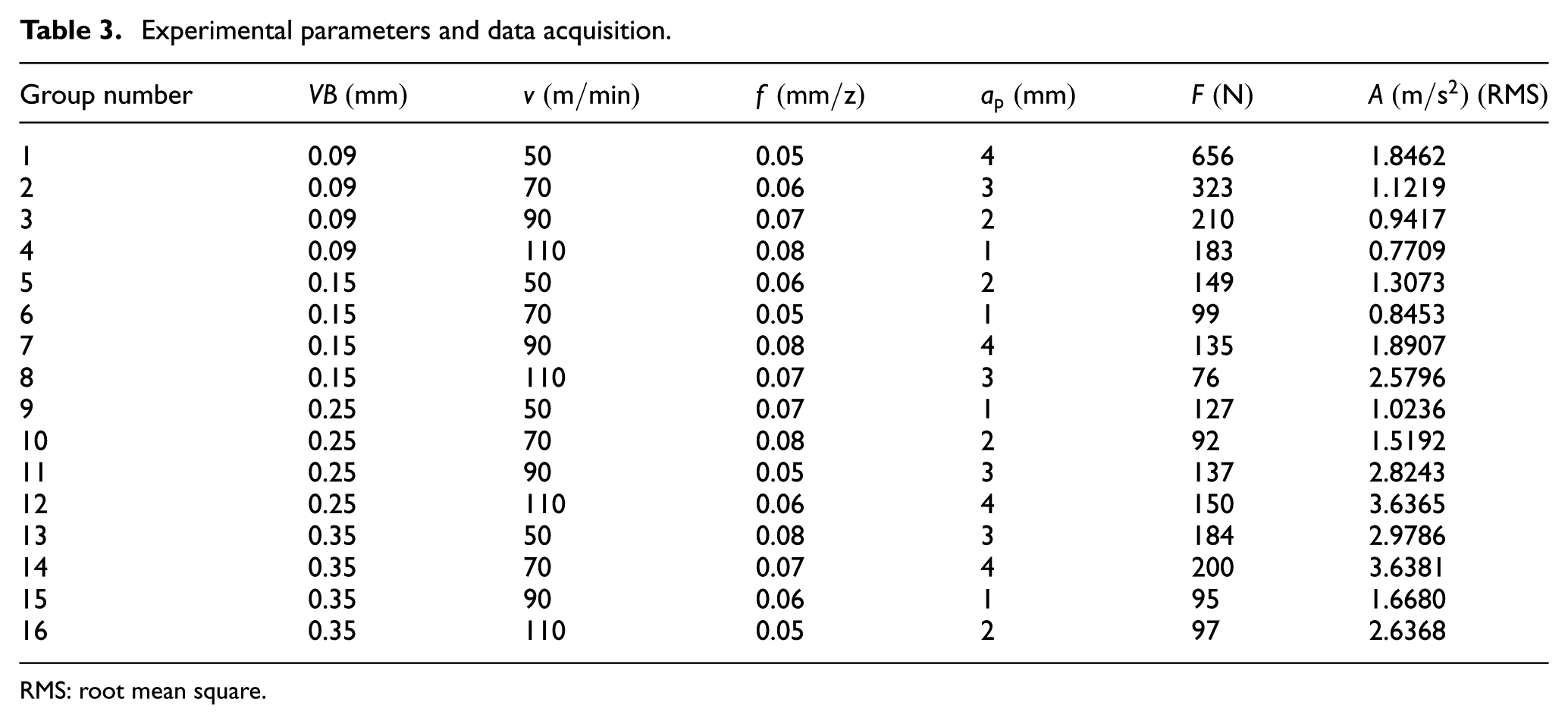
RMS: root mean square.
The wear on the tools was measured using the following procedure:
The tool shank and positions of tool bits 1 and 2 were marked. A black spot was marked where the generatrix of the shank was vertical to the normal of the primary tool flank. An infrared (IR) emitter was fixed onto the Smartzoom 5 so that IR ray emitted was parallel to the normal of the primary tool flank and coincided with the black spot (Figure 3(a) and (b)).
To guarantee that different tools were in the same position under the lens, a white rectangular block was pasted onto the display screen. During each observation process, the end of the tool bit was checked to ensure that it coincided with the block (Figure 3(c)).
To ensure the same measuring position was used, the coordinate system in the Smartzoom 5 was employed (the coordinate system was determined according to special points in the tool image taken before wear was incurred). The tool nose was taken as the origin. A distance equal to two-thirds of the cutting depth used in the experiment was measured along the blade line. Then, the horizontal and vertical coordinates of the point corresponding to this two-thirds depth were ascertained. The straight line passing through this horizontal coordinate was employed as the line used to monitor the tool wear. Clearly, the tool nose could not be determined once the tool had started to wear. Therefore, the tool root was used as the standard location to which the relative amount of tool wear was recorded. Subsequently, all the coordinates used were recorded and used to calculate the degree of tool wear (Figure 3(d) and (e)).
Pictures were taken of the tools after putting them into the set reference position. Using the coordinates determined before wear started, the wear-monitoring line could be obtained from the tool image. The initial wear point on the line was manually moved to the bottom edge of the tool wear area and the vertical coordinate recorded. The extent of tool wear could then be acquired by finding the difference between the vertical coordinates before and after the movement. Finally, the data were recorded (Figure 3(f)).
The extent of tool wear grows with time (i.e. the wear value measured each time is larger than that previously measured). Thus, any decline in the extent of wear suggests that errors are present in the experimental results (this may be caused by various uncertain factors, for example, local non-uniformity in the tool texture and inaccurate monitoring of the wear line). Therefore, the whole of the wear area was analysed macroscopically during data acquisition to help eliminate (as far as possible) the effects of accidental factors on the experimental data. In addition, measurements were conducted three times in order to avoid errors during the measurement process. These measurements were then averaged and the mean is taken as the extent of wear of the tool flank.
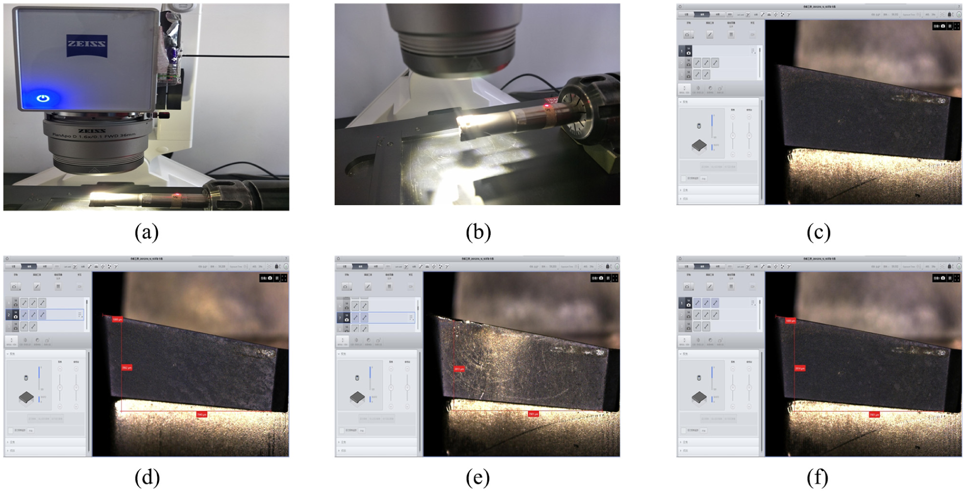
The tool wear measurement: (a) place tool, (b) aim, (c) coincidence, (d) abscissa position, (e) ordinate position and (f) record data.
Experimental results and analysis
Tool wear mechanisms
SEM images of rake face of the tool after 82 min of the milling are illustrated in Figure 4, while Figure 5 shows the energy spectra of points B, C, D and E in Figure 4 and point E represents the original component of the tool coating. As shown in Figure 4, wear morphologies, such as adhesive wear (Figure 4(f)), oxidation wear (Figure 4(a) and (d)), diffusion wear (Figure 4(a) and (d)), mechanical cracking and thermal cracking (Figure 4(c)), appear on the rake face. 022Cr17Ni 12Mo2 stainless steel is characterised by its good high-temperature strength, a large friction coefficient, a low thermal conductivity, a small tool–chip interface and work hardening. Therefore, in any milling process, both large cutting forces and high cutting temperature, are found on the tool–workpiece interface. The mechanical stresses are generated due to mutual friction between surfaces of the tool and workpiece cause coatings on tool surfaces to generate cracks and cause a loss of cohesion between coating and matrix materials, thus leading to coating stripping. Furthermore, as milling is a discontinuous cutting process, mechanical and thermal cracks are produced owing to cutting edges being affected by cutting forces and temperature changes, as demonstrated by data from point A in Figure 4. By analysing Figure 5(a) and (b) and comparing the energy spectra and elemental compositions at points B and C with the original composition of the tool coatings at point E, oxygen is found in wear area of the rake face of the tool and in the marginal wear area. The reason is that milling is a discontinuous cutting process and air readily permeates the interface between any chips and the rake face of the tool to oxidise tool materials at the high temperatures typically found in such milling processes. For example, tool matrices with W and Co are oxidised to generate oxides, such as WO3 and CoO. Furthermore, owing to oxides of hard carbide tool materials being soft and loose, the materials easily fall off and are damaged by friction between chips and workpiece materials under mechanical impact during cutting. Afterwards, the materials are reoxidised and then rubbed constantly. The repetition of the process results in oxidation wear on the rake face of the tool. 8 In milling process, with the constant relative movement between workpiece materials and tools, the flow of chips on the rake face maintains a high concentration gradient of tool elements in the interface between tool and chips. Moreover, the chemical elements on frictional surfaces of tools and workpieces can diffuse into each other and thereby change their relative chemical compositions. As a result, it weakens the material properties of the tool, accelerates tool wear and produces diffusion wear. 13 As shown in Figure 5(a) and (b), under the effects of high temperature and the concentration gradient in the area of the cutting edge at points B and C, the elements between the tool materials and the chip materials diffuse mutually. This leads to the diffusion of elements including Ti, Al, Fe, Co and W in the tool materials to the bottom of the chips. This causes diffusion wear on the rake face of the tool, which not only reduces the hardness and tenacity of tool materials but also accelerates the wear of the rake face of the tool. 14 In addition, chemical reactions occur between some elements in tool materials and some surrounding media to generate different oxidation films and adhesion films at certain temperatures during cutting. Some films play a protective role in preventing further oxidation, while others form soft compounds, making hard phase particles in tool materials more easily removed, thus weakening the material properties of the tool and aggravating tool wear. As shown in Figure 5(c), a large amount of Cr, Fe and Ni was found at point D, and the components are basically consistent with workpiece materials. This is because, at high temperature and pressures, chips undergo plastic deformation and adhere to the rake face in the vicinity of the cutting edge. They form bonding layers and further develop into built-up edges which serve as cutting edges. After adhesive materials gradually accumulate to a certain degree, the bonding layers fall off and remove some tool materials under the large alternating stresses generated due to discontinuous cutting. With the constant relative movement of chips, workpiece materials and the tool, elements in tool materials diffuse into, and are taken away by, chips and workpiece materials, resulting in adhesive wear on the rake face of the tool.15,16

SEM images of rake face: (a) oxidation and diffusion wear, (b) distribution graph, (c) mechanical and thermal cracking, (d) oxidation and diffusion wear, (e) original component of the tool coating and (f) adhesive wear.

EDS plots of points in Figure 3: (a) location of point B, (b) location of point C, (c) location of point D and (d) location of point E.
Figure 6 illustrates SEM images of the flank face of the tool, while Figure 7 shows the energy spectra of points B, C, D and E. It can be seen from Figure 6 that wear morphologies, such as adhesive wear (Figure 6(a)) and diffusion wear (Figure 6(d) and (f)), are present on the flank face and the shedding in patches of bonding layers accelerates tool wear. The ablation phenomenon appears on coatings near such wear positions. The flank face mainly exerts its effect on the workpiece through extrusion and friction, which do less work compared with shear action. Therefore, the temperature of the interface of the flank face and workpieces is lower than that at the rake face and thus does not show obvious thermal cracking. As shown in Figure 7(a), a significant amount of Cr, Fe and Ni was found at point B where the elemental components are basically consistent with those of 022Cr17Ni12Mo2 stainless steel. Moreover, owing to Co in the tool materials belonging to the iron family, just as the Fe and Ni in workpiece materials, these elements show high chemical affinity and are easily bonded. In addition, cutting heat and compressive stresses caused by the temperature gradient are generated when the tool cuts into the workpiece during milling, bind the tool and workpiece at high temperatures and pressures, thus causing adhesive wear. 14 Co and W are the main elements found at point C in Figure 7(b), indicating that coatings fall off thus exposing the matrix materials of the tool. In the milling process, a concentration gradient develops across tool–workpiece interface, as seen at point D in Figure 7(c), which also results in the diffusion of elements in tool metals to the workpiece materials, thus causing diffusion wear on the flank face of the tool. The results of energy spectrum analysis at point D indicate that the contents of Cr and Fe are only 5.79% and 18.59%, while elements such as Ti, Al and Co account for even smaller proportions. The loss of Co is mainly caused by the combined effects of diffusion and bonding. 16

SEM images of flank face: (a) adhesive wear, (b) distribution graph, (c) mechanical and thermal cracking, (d) diffusion wear, (e) original component of the tool coating and (f) diffusion wear.

EDS plots of points in Figure 5: (a) location of point B, (b) location of point C, (c) location of point D and (d) location of point E.
On one hand, Co, in this form, has a strong mobility, so it easily diffuses during the milling process under the effects of temperature and concentration gradient. On the other hand, owing to Co, just like Fe and Ni, belonging to the same family, they have high chemical affinity and Co is easily bonded and removed; however, in the milling process, the flank face shows significantly lower milling temperatures than the rake face and a far smaller diffusion coefficient on its tool–workpiece interface than on its tool–chip interface. 15 Therefore, the amount of wear of the flank face of the tool is smaller than that suffered by the rake face.
Tool wear patterns
The wear patterns of the tool are mainly shown as wear on the rake face and flank face as well as at its boundary. Owing to complex cutting process, mul-tiple wear patterns can appear at the same time. 022Cr17Ni12Mo2 stainless steel is a material that is difficult to machine. In a cutting process, significant friction occurs between the rake face of the tool and chips, as well as between the major flank face and machined surfaces, producing very high contact pressures and temperatures as well as wear on the major rake face and major flank face on the boundaries of the tool. The change in wear depth

The change rule of tool wear.
Changes in cutting force with tool wear
Figure 9 demonstrates the changes in cutting force

Variation of cutting force with cutting time.
Changes in cutting vibration with tool wear
Figure 10 demonstrates the changes in the root-mean-square value of vibration acceleration signals with wear depth of the flank face of the tool and time in this cutting process: in the initial wear stage, vibration amplitudes fluctuate slightly and show a slight decrease and then a rapid increase. In the stable wear stage, due to the high rigidity of the process system in the z direction,

Cutting amplitude of vibration with cutting time.
Influences of process factors on cutting force and vibration
Effects of milling parameters on cutting force
Table 4 shows the results of averaging method and variance analysis on cutting force
The effects of averaging method and variance analysis on cutting force.
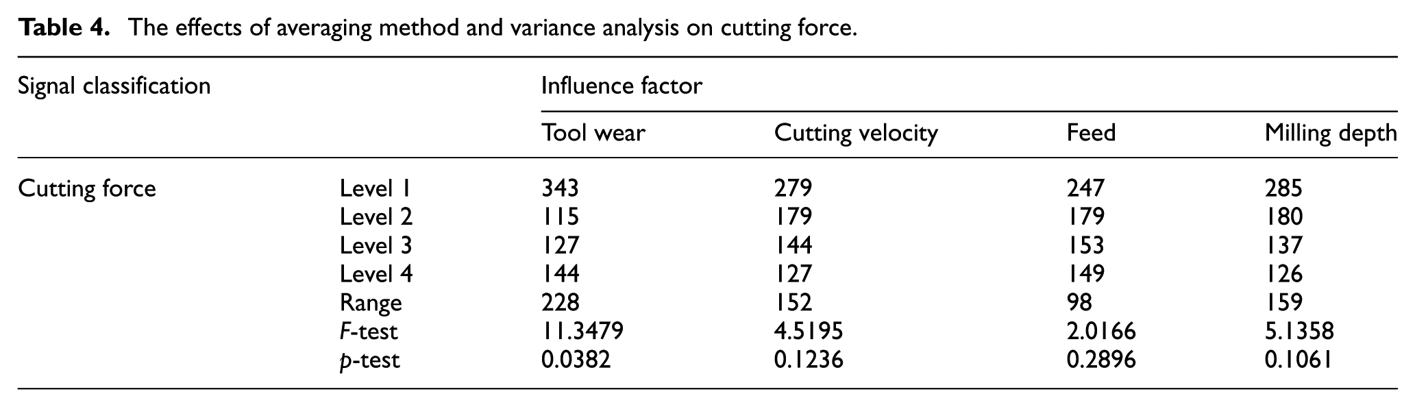
Figure 11 shows the main effects of the mean amplitude of cutting force signals: within the given range of cutting parameters, with the increase in the cutting velocity, the milling force gradually decreases, mainly because built-up edges are easily produced when cutting at medium and low speeds, resulting in unstable cutting processes and large cutting forces. With increasing cutting velocity, the cutting temperature gradually rises, so that softening occurs in materials and the cutting force decreases. Therefore, in actual machining work, the cutting force can be reduced by increasing the cutting velocity. In comparison, the feed rate exerts a small effect on the milling force: milling forces decrease slightly with increased feed rate. Although the increased feed rate can enlarge the cutting area and increase deformation resistance, it can increase the cutting width, reduce deformation and result in a lower friction coefficient, thus improving the flow of chips, and thus decreasing the milling force (Figure 11(b)). 8 The milling depth significantly affects the cutting force: with constant increases in milling depth, the cutting force gradually increases because the increased cutting depth directly enlarges the cutting area, thus increasing the overall deformation resistance; thereafter, the cutting force increases with cutting depth (Figure 11(c)).

The main effects of the mean amplitude of cutting force signals: (a) main effects of milling speed, (b) main effects of feed speed, (c) main effects of cutting depth and (d) main effects of wear.
Effects of tool wear on milling force
It can be seen from Figure 11(d) that the milling force first decreases and then gradually increases with the constant increase in the tool wear. When tool wear depth
Effects of milling parameters on milling vibration
Table 5 shows the results of the averaging method and variance analysis as applied to the vibration acceleration signals and their root-mean-square values.
The effects of averaging method and variance analysis on vibration acceleration signals.

As shown in Figure 12(a), the milling vibration first decreases and then increases with rising cutting velocity within the given range of cutting parameters. This is mainly because built-up edges are easily formed during medium- and low-speed cutting, resulting in unstable cutting and severe cutting vibration. After the cutting velocity increases to 60 m/min, the cutting temperature gradually rises with increasing milling velocity, which softens the materials and reduces the cutting force, thus decreasing the cutting vibration. 17 However, when the cutting velocity is greater than 90 m/min, the vibration is aggravated due to the decrease in the rigidity of the high-speed cutting machine tool. 18 Therefore, cutting vibration can be reduced by properly increasing the cutting velocity in actual machining work. Furthermore, the feed rate has a small effect on the milling vibrations. As the feed rate increases, milling vibration decreases slightly. Although the increased feed rate can enlarge the cutting area and increase the deformation resistance, it can increase the cutting width, reduce deformation, cause a decrease in the friction coefficient, improve chip flow and decrease the dynamic cutting force, thereby reducing milling vibration (Figure 12(b)). Milling depth exerts obvious influences on cutting vibration: with the constant increase in the milling depth, cutting vibration first increases in intensity because, at very small milling depths, the milling tool edge finds it hard to cut into materials and significant rubbing occurs between the tool edge and the workpiece surface, which greatly affects the stability of cutting process. As the milling depth constantly increases, the cutting force also increases continuously, thus increasing any cutting vibrations (Figure 12(c)).

The main effects of the mean amplitude of acceleration signals: (a) main effects of milling speed, (b) main effects of feed speed, (c) main effects of cutting depth and (d) main effects of wear.
Influences of tool wear on milling vibration
As shown in Figure 12(d), milling vibration constantly increases with tool wear. Tool wear, in different stages, exerts different effects on cutting vibration and the trends therein are similar to those exhibited by the tool wear process. When the tool wear depth
Conclusion
Through cutting experiments using a coated hard carbide end mill to mill 022Cr17Ni12Mo2 stainless steel, the following conclusions are drawn:
When the 022Cr17Ni12Mo2 stainless steel is milled using the coated hard carbide end mill, the rake face is mainly subjected to adhesive, oxidative and diffusive wear, along with mechanical and thermal cracking and the flaking of bonding layers, all of which accelerate tool wear while adhesive wear and diffusion wear mainly appear on the flank face. In the milling process, the milling temperature of the flank face is significantly lower than that of the rake face, and the diffusion coefficient across the tool–workpiece interface is much smaller than that across the tool–chip interface. Therefore, the flank face is slightly less worn than the rake face of the tool.
The wear patterns of the tool are mainly shown as wear of the rake and flank faces as well as at the boundaries. The tool wear in this milling process can be divided into an initial wear stage, a normal wear stage and a severe wear stage. The tool is worn rapidly in the initial and normal wear stages, while wear depths increase significantly in the severe wear stage.
In the cutting process, the cutting force is the greatest, and changes most significantly, in the y direction. Moreover, it increases with tool wear and shows similar trends to those exhibited by the tool wear. Vibration amplitudes fluctuate slightly in the initial wear stage, then slowly increase in the stable wear stage and dramatically increase, with more significant fluctuations seen, in the severe wear stage.
Process factors including tool wear, milling depth, cutting velocity and feed rate have descending effects on cutting force, while they are arranged (in decreasing order) as follows: milling depth, tool wear, cutting velocity and feed rate in terms of their influences on vibration amplitude. On the premise of meeting the requirements of the rigidity and surface roughness of machine tools in actual machining operations, productivity can be improved and the cutting force and vibration can be controlled by properly increasing both the cutting velocity and milling depth.
Footnotes
Handling Editor: Davood Younesian
Declaration of conflicting interests
The author(s) declared no potential conflicts of interest with respect to the research, authorship, and/or publication of this article.
Funding
The author(s) disclosed receipt of the following financial support for the research, authorship, and/or publication of this article: This project was supported by The National Natural Science Foundation of China (grant no. 51465029). The authors thank Gansu Province University Collaborative Innovation Team Construction Plan for their support (grant no. 2016C-07) and the fund for Lanzhou Talent Innovation and Entrepreneurship (project grant no. 2015-RC-4).